Note : Les descriptions sont présentées dans la langue officielle dans laquelle elles ont été soumises.
CA 02547704 2006-05-30
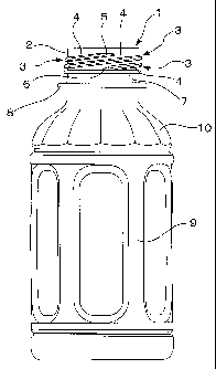
1
NECK OF A SYNTHETIC RESIN BOTTLE
Technical Field
[0001] This invention relates to a neck of a synthetic resin bottle that is
drawn and blow molded from a synthetic resin material, and in particular, to
the structure of a neck that has pressure tightness, heat resistance, and a
high,
stable sealing property and shows a resource saving advantage.
Background Art
[0002] The neck of a bottle is given high heat resistance and rigidity by
whitening the neck in the thermal crystallization treatment. Such a neck is
used for the synthetic resin bottle to be filled with tea, fruit juice, liquid
seasoning, retort-packed food and the like at a high temperature or to be
subjected to an intermediate process, such as a thermal sterilization process,
and is used especially for the biaxially drawn, blow-molded bottle made of a
polyethylene terephthalate resin (hereinafter referred to as PET bottle). (See
Patent Document 1.)
[Patent Document 11: Application No. 1998-058527
[0003] A multi-threaded screw structure is adopted to shortcut the rotating
movement required to fit or remove the screw cap or to reduce the amount of
synthetic resin material required to mold a neck. The multi-threaded screw
structure is utilized, especially for most of wide-mouth bottles, so that the
neck
does not become too tall.
[0004] In most cases, the cap screwed on the PET bottle is not an aluminum
pilfer-proof cap that requires large screwing strength, but a synthetic resin
pilfer-proof cap that does not require much strength. The neck of a PET bottle
can have the wall thickness and bead ring size that are smaller than those
used in the case where the aluminum pilfer-proof cap is put on. Thus, the
synthetic resin pilfer-proof cap gives a higher resource-saving effect.
[0005] As shown in the rolled-out view of Fig. 11, the neck in the
conventional art is provided with a number of screw threads 30, which amount
to three in Fig. 8, and these threads 30 are disposed at an equal central
angle
on the outer surface of round neck wall 2. Each main thread 40 primarily
carries out the screwing function of each screw thread 30. The anterior half
of
the main thread 40 of a screw thread 30 is located above the posterior half of
a
CA 02547704 2006-05-30
2
neighboring screw thread 30. In turn, the posterior half of the main thread 40
of the first screw thread 30 is located beneath the anterior half of the main
thread 40 of still another screw thread 30.
[0006] Each screw thread 30 is provided with a starting portion 50 at the
start of the main thread 40 and an ending portion 60 at the end of the main
thread 40. This starting portion 50 has reduced dimensions for smooth screw
engagement and release from the mold. The ending portion 60 too has reduced
dimensions for smooth release from the mold.
[0007] The main thread 40 of a screw thread 30 is located above the main
thread 40 of another screw thread 30 in a main zone that performs the
screwing function. Between a main zone and another neighboring main zone
there is an auxiliary zone that helps the main zones perform the screwing
function. This auxiliary zone includes a starting portion 50 of a screw thread
30, an ending portion 60 of another screw thread 30, and a part of the main
thread 40 of still another screw thread 30.
[0008] The screw engagement between the neck and a screw cap is achieved
in the main zones, which are equally spaced in the circumferential direction
and in which the above-described screwing function is performed. On the
other hand, the above-described auxiliary zones do not need to accept large
screwing and fitting force. Therefore, the starting portion 50 and the ending
portion 60 of these screw threads 30 are molded in sizes as small as possible
within a range in which mold release and screw engagement can be achieved
smoothly.
Disclosure of the Invention
Problem to be solved by the invention
[0009] The above-described conventional art had a problem in that there
occurs contractile deformation, causing sinks (h) (See Fig. 11) in the top end
face of the round neck wall 2 and thus giving damage to the sealing property
of
the neck. This contractile deformation was incurred by the thermal
crystallization treatment conducted under conditions of decreased thickness of
the round neck wall 2, a large reduction in dimensions, especially height and
width, of the bead ring 7, and a high temperature of about 180 C used to
obtain heat resistance that makes the bottle usable as the container of retort-
packed foods.
CA 02547704 2011-05-13
23939-85
3
[0010] For example, in the case shown in Fig. 11, it was confirmed that there
occurred large sinks (h) (actually having the size in the order of a tenth of
1 millimeter, but was shown in Fig. 11 in an enlarged view for easiness to
understand) in the area covering the central angle position in the range of 20
to
40 degrees toward the screwing direction from the auxiliary screwing zone.
[0011] It is believed that these sinks (h) have occurred because of decreased
thickness of the round neck wall 2 and a large reduction in dimensions,
especially
height and width, of the bead ring 7. Under these conditions, the flow of
molten PET
is affected by the thread-formed portions at the time when the neck is
injection
molded, causing a difference in the degree of the molecular orientation. This
difference has a large effect on the uniform thermal crystallization treatment
of the
entire neck, and creates a large difference in the degree of crystallization
among
various portions of the neck.
[0012] This invention has been made to solve the above-described problem found
in conventional art. The technical problem of this invention is to equalize
the effect of
thread-formed portions on the molecular orientation of the molten resin
material as
much as possible along the circumferential direction of the neck. The object
of this
invention is to obtain a resource-saving neck having high resistance to
pressure and
heat and high, stable sealing property.
Means of solving the problem
[0013] In the following description, the main thread zone is defined as a
circumferentially extending zone of the neck where at least two main threads
are
disposed, with one thread laid above the other. The thread extension zone is
defined
as a circumferentially extending zone of the neck where at least one starting
extension of a screw thread is disposed above the ending extension of another
screw
thread.
[0014] The means of carrying out a first aspect of the invention to solve the
above-described technical problem is a neck of a synthetic resin bottle
comprising a
CA 02547704 2011-05-13
23939-85
4
round neck wall and multiple screw threads of a multi-threaded screw structure
disposed on the outer surface of the round neck wall, each screw thread
comprising a
main thread in charge of a screwing function, a starting extension extending
from a
main thread start point of the main thread with width and height thereof being
reduced gradually from the dimensions of said main thread and an ending
extension
extending from a main thread end point of the main thread with width and
height
thereof being reduced gradually from the dimensions of said main thread,
wherein the starting extension of a screw thread is vertically disposed above
the
ending extension of another thread, with both extensions in the same length,
and
wherein the neck is entirely whitened by thermal crystallization.
[0015] The sinks or dents caused by thermal crystallization in the top end
face of
the conventional neck must have developed presumably in the following
mechanism:
An injection-molded preform in a test-tube shape is used for biaxial drawing
and blow
molding. In the injection molding operation, a molten resin is injected into
the mold
through the preform bottom position and is allowed to flow toward the top end
face of
the neck. At that time, a large difference in the resin flow state grows in
the
circumferential direction of the neck, depending on the layout of screw
threads on the
outer surface of the round neck wall, including the position of a starting
portion or an
ending portion of each screw thread, the number of screw thread rows that are
in
parallel, and the like.
[0016] The temperature of the resin goes down in the vicinity of the top end
face of
the round neck wall because the flow is coming close to an end in this
portion. The
differences in the pressure state and in the molecular orientation grow large
under
the effect of the flow state. Because the resin is in the final stage of flow,
with
subsequent clamping and cooling processes waiting, there is only a short
period
available for the molecular orientation to be absorbed. Therefore, in the
molded
product, there remains a difference in the state of molecular orientation that
has
occurred during the flow. This state of remaining molecular orientation is
likely to
CA 02547704 2011-05-13
23939-85
cause a large difference in the degree of shrinkage in the thermal
crystallization
behavior.
[0017] In a first aspect of the invention, the starting extension is disposed
above
the ending extension, in which the large-size portion of the starting
extension is
5 disposed above the small-size head of the ending extension, and the small-
size head
of the starting extension is disposed above the large-size portion of the
ending
extension. Thus, the starting extension and the ending extension are
complementary
to each other in their positions.
[0018] Due to the mutual complementation of vertical unevenness, the flow
state of
molten PET can be equalized in the circumferential direction of the neck
including the
starting and ending extensions. As a result, the degree of oriented
crystallization can
be made uniform, and thus the sinks caused by thermal crystallization can be
controlled effectively in the top end face of the neck.
[0019] A second aspect of the invention includes the configuration of the
first
aspect and also comprises that the starting extension and the ending extension
are
formed, with width and height thereof being reduced gradually at the same,
roughly
constant rates from the start point and the end point of the main thread.
[0020] In the second aspect, the starting and ending extensions are formed,
with
dimensions reduced gradually at the same, roughly constant rates from those of
the
main thread measured at the start point and the end point of the main thread,
but in
the direction opposite to each other. The two extensions have the same
structure
except that the directions are opposite. Therefore, the extent of unevenness
obtained from complementary positions of extensions is roughly equivalent to
that
obtained from the main threads of screw threads.
[0021] A third aspect of the invention includes the configuration of the first
and
second aspects and also comprises that the neck has a multi-threaded spiral
structure of screw threads in a number of n, with n being 2 or a larger
integer,
wherein main thread zones amounting to the number of n are formed in a central
CA 02547704 2011-05-13
23939-85
6
angle range of a little less than 360 /n, in which zones the main threads of
at least
two screw threads are disposed obliquely in parallel, with one main thread
laid above
the other, and wherein each thread extension zone is formed between two of
said
main thread zones that are equally spaced around the neck, with the starting
extension of at least one screw thread being disposed above the ending
extension of
another screw thread in these thread extension zones.
[0022] In the third aspect, the main thread zones amounting to the number of n
are
formed in a central angle range of a little less than 360 /n, and the main
threads of at
least two screw threads are disposed obliquely in parallel, with one thread
laid above
the other, in these main thread zones. Therefore, the central angle range of a
thread
extension zone is calculated by:
[(360 /n) - (the central angle range of a main thread zone)]
This makes it possible to set the central angle range of the thread extension
zone
and to set a short length for the starting extension and the ending extension
properly.
[0023] A fourth aspect of the invention includes the configuration of the
first,
second, and third aspects of the invention, and also comprises forming a
groove in
the outer surface of a round neck wall in the circumferential direction at a
height
above the screw threads, at a specified central angle position, and in a
specified
central angle range to protect the neck against sinks, which tend to develop
in the top
end face of the round neck wall under the effect of thermal crystallization
treatment,
and then whitening the neck by the thermal crystallization treatment.
[0024] The configuration concerning the groove of the fourth aspect is added,
if
necessary, to the configuration concerning the positions of the starting
extension and
the ending extension of each screw thread according to the first to third
aspects,
where the starting extension is vertically disposed above the ending
extension. This
groove configuration is aimed at effectively controlling the sinks caused by
thermal
crystallization in the top end face of the neck.
CA 02547704 2011-05-13
23939-85
7
[0025] In the fourth aspect of the invention, a peripheral groove or groove
segments are formed in the upper portion of the outer neck wall in the
circumferential
direction, at a height above the screw threads, at a specified central angle
position,
and in a specified central angle range while consideration is given to the
layout of the
screw threads. The entire flow of resin can be adjusted by narrowing the resin
flow
passage at the circumferential positions where the groove is formed. Because
of this
adjustment, it is possible to reduce the differences in the flow state in the
circumferential direction and in the state of molecular orientation and to
control
effectively the occurrence of sinks that develop in the top end face of the
neck due to
the thermal crystallization treatment.
[0026] The groove formed in the round neck wall can be effective even if it is
about
1/10 as deep as the wall thickness. The groove serves to prevent the sinks
from
occurring, within the limit that no damage is given to the seal formed between
a
portion of outer surface right under the top end face of the round neck wall
and the
upper portion of the inside wall of a screw cap. In addition, the groove can
be made
inconspicuous in its external appearance.
[0027] It is likely that this groove has the above-described action and effect
because the groove is placed above the screw threads and in close vicinity of
the end
of resin flow where the resin has a considerably low temperature and a high
viscosity.
Under these conditions, it is fully possible to adjust the state of molecular
orientation
merely by changing the slight depth of the flow passage.
[0028] An optimum shape of the groove can be basically determined from
experiments by checking on the extent of sinks. The groove can be variously
formed
by changing such factors as the number of groove or grooves, the height at
which the
groove is disposed laterally, circumferential position and range, groove
depth, and
groove width.
[0029] The means of carrying out a fifth aspect of the invention comprises
that the
groove of the fourth aspect is formed around the neck as intermittent groove
segments.
CA 02547704 2011-05-13
23939-85
8
[0030] Under the configuration of the fifth aspect of the invention, the
groove can
be formed intermittently as groove segments, depending on the observed state
of
sink occurrence. Thus, the flow state is adjusted by simple-shaped groove
segments
in the circumferential direction so that the sinks can be controlled
effectively.
[0031] A sixth aspect of the invention includes the configuration of the third
aspect
of the invention, and also comprises that the groove is formed as peripheral
groove
segments around the neck in the outer neck wall at the height above screw
threads,
except in the thread extension zones, to control the sinks caused by thermal
crystallization in the top end face of the neck.
[0032] In the sixth aspect of the invention, the groove is formed around the
neck,
except in the thread extension zones where molten resin flow passages undergo
a
larger change than in the main thread zones. If the width of resin flow is
narrowed in
the area where the groove has been formed, then the effect of the change in
the resin
flow state of the thread extension zones can be adjusted at the time of
injection
molding of the preform. Thus, the sinks can be controlled effectively when the
groove
is combined with the configuration of the starting and ending extensions that
are
disposed vertically with one above the other.
[0033] A seventh aspect of the invention includes the configuration of the
first to
sixth aspects of the invention, and also comprises that a bead ring is
disposed on the
outer surface of the round neck wall right under the threaded area and is used
to fit a
pilfer-proof cap made of a synthetic resin.
[0034] In the seventh aspect of the invention, a bead ring is formed so that a
pilfer-
proof cap made of a synthetic resin can be fitted to the neck by means of this
bead
ring. In addition, the effect of screw threads on the molecular orientation
can be
softened to some extent by forming the bead ring.
[0035] An eighth aspect of the invention includes the seventh aspect of the
invention, and also comprises that a bead ring and a neck ring are disposed in
the
CA 02547704 2011-05-13
23939-85
9
lower portion of the neck below the screw threads and that the neck including
these
bead ring and neck ring is whitened by the thermal crystallization treatment.
[0036] In the eighth aspect of the invention, the bead ring and the neck ring
are
disposed, if necessary, in the lower portion of the neck, and the neck
including these
rings is whitened by thermal crystallization. Because of these bead ring and
neck
ring, relatively thick portions are formed peripherally in the lower portion
of the neck,
and can be used to soften the effect of screw threads on the resin flow to
some
extent.
Effects of the Invention
[0037] This invention having the above-described configuration has the
following
effects: Due to the mutual complementation of unevenness, the first aspect of
the
invention enables the flow state of molten PET to be equalized in the
circumferential
direction of the neck including the starting and ending extensions. As a
result, the
degree of crystallization can be made uniform, and thus the sinks caused by
thermal
crystallization can be controlled effectively in the top end face of the neck.
The first
aspect of the invention also enables the neck to have a strong and stable
sealing
property.
[0038] In the second aspect of the invention, an improved extent of unevenness
is
obtained by the positional complementation between the starting extension and
the
ending extension, in which the former is disposed vertically above the latter.
Since
the extent of this complemented unevenness is almost equivalent to the extent
of
unevenness obtained from the main screw threads, the molecular orientation
state
can be uniformly distributed over the entire periphery of the neck. Therefore,
a
sufficient preventive effect against sinks can be obtained from complemented
unevenness.
[0039] In the third aspect of the invention, it becomes possible to set a
central
angle range suitably in the thread extension zone, where the starting
extension is
disposed above the ending extension, and thereby, to set a suitable length for
both of
CA 02547704 2011-05-13
23939-85
9a
the starting and ending extensions so that the entire multi-threaded screw
structure
can be simplified. For example, if the main thread zones are formed in a
central
angle range of a little less than 360 /n, then it is possible to reduce the
central angle
range of the thread extension zone and to set a short length for the starting
extension
and the ending extension, which are disposed vertically with one extension
above the
other.
[0040] In the fourth aspect of the invention, the resin flow state is adjusted
by
forming the groove in the circumferential direction at a specified position
and in a
central angle range. Coupled with the configuration concerning the positions
of the
starting and ending extensions of screw threads, with the starting extension
being
disposed above the ending extension, this adjustment serves to reduce the
differences in both of the state of the flow in the circumferential direction
and the
molecular orientation state. Thus, the sinks caused by the thermal
crystallization
treatment can be prevented effectively from developing in the top end face of
the
neck.
[0041] In the fifth aspect of the invention, the groove can be formed
intermittently
as groove segments, depending on the observed state of sink occurrence. Thus,
the
state of flow in the circumferential direction is adjusted effectively by the
groove
segments in a simple shape.
[0042] In the sixth aspect of the invention, the resin flow state in the
thread
extension zones can be adjusted so as to offset the effect of changes in the
resin flow
and to control the sinks effectively.
[0043] In the seventh aspect of the invention, the pilfer-proof cap made of a
synthetic resin can be fitted to the neck, and the effect of screw threads on
the
molecular orientation crystallization can be reduced to some extent.
Therefore, the
controlling effect against sinks can be further increased.
CA 02547704 2011-05-13
23939-85
9b
[0044] In the eighth aspect of the invention, the sinks can be more
effectively
controlled because the bead ring and the neck ring are used to soften the
effect of
screw threads on the resin flow to some extent.
Brief Description of the Drawings
[0045] Fig. 1 is a front elevational view of the bottle adopted in one
embodiment of
this invention.
Fig. 2 is a plan view of the embodiment shown in Fig. 1.
Fig. 3 is an enlarged vertical section of an important part of the
embodiment shown in Fig. 1.
Fig. 4 is an enlarged plan view of an important part of the embodiment
shown in Fig. 2.
CA 02547704 2006-05-30
Fig. 5 is an enlarged vertical section of an important part of the
embodiment shown in Fig. 4, cut vertically at the position (e).
Fig. 6 is an explanatory plan view showing the relationship between main'
thread zones and thread extension zones of the neck shown in Fig. 1.
5 Fig. 7 is an explanatory diagram of the neck shown in Fig. 6, which has
been rolled out.
Fig. 8 is a front elevational view of a bottle with the neck adopted in the
second embodiment of this invention
Fig. 9 is an explanatory plan view showing the positional relationship
10 among the main thread zones, the thread extension zones, and the groove of
the neck shown in Fig. 8.
Fig. 10 is an explanatory diagram of the neck shown in Fig. 9, which has
been rolled out.
Fig. 11 is an explanatory diagram showing the rolled-out screw threads in a
multi-threaded screw structure found in conventional art.
Explanation of Codes
[00461
1 ; Neck
2 ; Round neck wall
3 ; Screw thread
4 ; Main thread
5 ; Starting extension
6 ; Ending extension
7 ; Bead ring
8 ; Neck ring
9; Body
10; Shoulder
11 ; Groove
12; Groove-missing portion
30; Screw thread
Main thread
; Starting portion
; Ending portion
35 a ; Main thread start point
b ; Main thread end point
c ; Position
d ; Position
e ; Position
40 f ; Main thread zone
CA 02547704 2006-05-30
11
g ; Thread extension zone
h ; Sink
Preferred Embodiments of the Invention
[0047] This invention is further described with respect to preferred
embodiments, now referring to the drawings. Figs. 1-7 describe the neck in the
first embodiment of this invention. Fig. 1 is a front elevational view of an
entire bottle having the neck in the first embodiment of this invention. The
bottle is a biaxially drawn, blow molded PET bottle, which comprises a body 9
having a bottomed cylindrical shape, a shoulder 10 having a truncated
dodecagonal cone shape, which is disposed at the upper end of the body 9, and
a neck 1 according to this invention, which stands upright from the shoulder
10.
[0048] The neck 1 has multiple screw threads 3 (three threads in the
embodiment shown in Fig. 1) of a continuous, multi-threaded screw structure
disposed on the upper half of the outer surface of a round neck wall 2. Right
under this multi-threaded structure there is a bead ring 7 exclusively used
together with a pilfer-proof cap made of a synthetic resin. This bead ring 7
is
short in height and is not connected to the screw threads 3. A neck ring 8
serving as a support ring is disposed at the lower end of the outer surface of
the round neck wall 2.
[0049] The neck 1 including the neck ring 8 is entirely whitened by thermal
crystallization (See Fig. 3). This thermal crystallization treatment is not
limited to the neck 1 only. As shown in Fig. 3 of this embodiment, thermal
crystallization can also be applied to the upper end portion of neck base,
which
denotes a portion connecting the neck 1 to the shoulder 10. In some cases,
roughly entire portion of the neck base can be thermally crystallized to a low
degree of crystallization.
[0050] Each screw thread 3 comprises the main thread 4 that primarily
carries out the screwing function, the starting extension 5 and the ending
extension 6 that extend from the start point (a) and the end point (b) of each
main thread 4, with width and height being reduced gradually at the same
constant rates from those of the main thread 4. The ending extension 6 has
the identical structure with the starting extension 5, but faces the direction
opposite thereto.
CA 02547704 2006-05-30
12
[0051] As shown in Figs. 4 and 5, the starting extension 5 has a structure in
which its width and height are reduced gradually at the same, roughly
constant rates as those of the ending extension 6, as the starting extension 5
extends from the position (c), which is the same point as the start point (a)
of
the main thread, through positions (d) and (e) toward the tip. The ending
extension 6 has the same structure but is only in the direction opposite the
starting extension 5.
[0052] Each screw thread 3 is formed in a central angle range of 280 .
Within this range, the main thread 4 covers a range of 200 , and the
starting/ending extensions 5 and 6 cover a range of 40 respectively.
[0053] As shown in Figs. 6 and 7, under the spiral structure of screw threads
3 formed on the neck 1, there are formed the main thread zones (f) in which a
part of a main thread 4 is disposed above a part of a. main thread of another
screw thread 3 and the thread extension zones (g) in which a starting
extension 5 of a screw thread 3 is disposed above an ending extension 6 of
still
another screw thread 3.
[0054] A screw thread 3 is intertwined with two other screw threads 3 in the
spiral structure. All in all, three main thread zones (f) are formed, with
each
zone (f) having a central angle range of 80 .
[0055] A thread extension zone (g) comprises a starting extension 5 of a
screw thread 3, a part of the main thread 4 of a neighboring screw thread 3,
and an ending extension 6 of another neighboring screw thread 3. Structurally,
the starting extension 5 is disposed above the portion of the main thread of a
neighboring screw thread 3, and this portion of the main thread 4 is disposed
above the ending extension 6. Each thread extension zone (g) is disposed
between two main thread zones (f) and has a central angle range of 40 .
[0056] As described above, the starting extension 5 and the ending extension
6 in a thread extension zone (g) has the same structure with an exception that
the two extensions are opposite to each other in their direction. Since the
width and height of these extensions are gradually reduced at the same,
roughly constant rates, the combination of the starting and ending extensions
is disposed vertically at the position of one above the other, and the two
extensions are in a mutually complementary relationship as far as uneven
height is concerned.
CA 02547704 2006-05-30
13
[0057] More specifically, the extent of unevenness resulted from a main
thread 4 can be achieved to a roughly equivalent level by a combination of the
starting and ending extensions 5 and 6 in this thread extension zone (g), in
which the starting extension is disposed above the ending extension.
[0058] Therefore, a combination of a starting extension 5, a main thread 4,
and an ending extension 6 is formed in each thread extension zone (g), and the
extent of vertically observed unevenness in the thread extension zone (g)
becomes roughly equal to the extent of unevenness developed by two main
threads 4 in the main thread zone (f).
[0059] Thus, the main thread zone (f) and the thread extension zone (g) are
roughly equivalent to each other in the extent of vertical unevenness brought
about by the screw threads 3. As a result, the two zones are also a good match
in the degree of the molecular orientation of the PET material. Therefore, the
sinks (h) can be prevented stably from developing in the top end face of the
round neck wall 2.
[0060] In the first embodiment shown in the drawings, the starting
extensions 5 and the ending extensions 6 of the screw threads 3 have a length
corresponding to the same central angle as the range of a thread extension
zone (g) formed between the start point (a) of a main thread and the end point
(b) of another main thread. The length of extensions is not necessarily
limited
to such a length, but a length slightly exceeding this central angle of the
thread extension zone (g) is allowed.
[0061] The neck 1 of the first embodiment shown in the drawings is 20 mm
high and 38 mm in diameter, and is provided with three screw threads in the
spiral structure although the multi-threaded screw structure is not specified
to
three screw threads. If the bottle needs to have a larger diameter than 38 mm,
while keeping the height at 20 mm, then the number of screw threads can be
adequately increased to more than three in response to the widened diameter.
[0062] Figs. 8-10 show the neck in the second embodiment of this invention.
Fig. 8 is a=front elevational view of an entire bottle with the neck in the
second
embodiment of this invention. Fig. 9 is an explanatory plan view showing the
positional relationship among the main thread zones (f), the thread extension
zones (g), and the groove 11 of the neck 1. Fig. 10 is an explanatory diagram
shown in Fig. 9, which has been rolled out. The neck 1 in the second
embodiment has the same shape as the neck in the first embodiment including
CA 02547704 2006-05-30
14
the multi-threaded screw structure, except that the peripheral groove 11 is
formed intermittently at positions right above the screw threads on the outer
surface of the round neck wall 2.
[0063] Groove-missing portions 12 are disposed in three thread extension
zones (g). Except in these groove-missing portions 12, the groove 11 is formed
intermittently as groove segments (See Figs. 8 and 9). In this embodiment, the
groove 11 is about 1/10 as deep as the thickness of the round neck wall 2.
[0064] The layout of the groove-missing portions 12 can be determined from
experiments by observing the positions (See Fig. 11) of sinks that have
occurred in the neck 1 having no groove 11 and correlating the positions of
sinks with the layout of screw threads 3, while giving consideration to the
resin flow state.
[0065] In this embodiment, the groove 11 is formed intermittently as
peripheral groove segments, and the groove-missing portions 12 are disposed
correspondingly, taking into consideration that the sinks (h) frequently
develop at the central angle position in the range of 20 to 40 degrees toward
the screwing direction from the main thread start points (a) of respective
screw
threads 3, as shown in Fig. 11.
[0066] In other words, it has been attempted to adjust the entire resin flow
by means of the groove 11 to narrow the resin flow in the portions other than
the groove-missing portions 12 in the vicinity of the end of resin now. The
sinks are prevented from occurring by forming the groove 11 intermittently as
peripheral groove segments.
[0067] The resin flow exhibits complicated behavior in the vicinity of the top
end face of the neck during the time when preform is being injection molded.
Although mechanism is not yet clear, the sinks occur frequently in the neck,
as
shown in Fig. 11, at three points determined by a central angle position in
the
range of 20 to 40 degrees from respective main thread start points (a).
However, it has been found that the behavior of resin flow or crystallization
can be adjusted by the groove 11 at the end of the resin flow, even in the
case
of a groove 11 about 1/10 as deep as the thickness of the round neck wall 2.
As
practiced in this embodiment, this can be done simply by correlating the
positions of sinks with the layout of screw threads 3 and by changing the
shape
of the groove 11 accordingly.
CA 02547704 2006-05-30
[0068] The groove can be utilized as a means of adjusting the resin flow
state in various manner. Not only the position of the groove, but also the
groove depth and width can also be changed as long as the groove does not give
damage to the sealing property that should be established between the upper
5 portion on the outer surface of the round neck wall and the screw cap. In
addition, plural peripheral grooves can be disposed around the neck. If
necessary, the groove configuration can be combined with the configuration
concerning the positions of the starting extension and the ending extension of
each screw thread, in which the starting extension is vertically disposed
above
10 the ending extension.
Industrial Applicability
[0069] As described above, the neck of this invention effectively controls the
sinks caused by the thermal crystallization treatment in the top end face of
the
15 neck. The neck of this invention is applicable to the retort-packed foods,
which
necessitate thermal crystallization treatment conducted at a high temperature
of about 180 C, and is expected to have a wide range of uses.