Sélection de la langue

Search

Sommaire du brevet 2547857 

Énoncé de désistement de responsabilité concernant l'information provenant de tiers

Une partie des informations de ce site Web a été fournie par des sources externes. Le gouvernement du Canada n'assume aucune responsabilité concernant la précision, l'actualité ou la fiabilité des informations fournies par les sources externes. Les utilisateurs qui désirent employer cette information devraient consulter directement la source des informations. Le contenu fourni par les sources externes n'est pas assujetti aux exigences sur les langues officielles, la protection des renseignements personnels et l'accessibilité.

Disponibilité de l'Abrégé et des Revendications

L'apparition de différences dans le texte et l'image des Revendications et de l'Abrégé dépend du moment auquel le document est publié. Les textes des Revendications et de l'Abrégé sont affichés :

  • lorsque la demande peut être examinée par le public;
  • lorsque le brevet est émis (délivrance).
(12) Demande de brevet: (11) CA 2547857
(54) Titre français: COUVERCLE POUR RECEPTACLE DE FIL A SOUDER
(54) Titre anglais: COVER FOR WELDING WIRE CONTAINER
Statut: Réputée abandonnée et au-delà du délai pour le rétablissement - en attente de la réponse à l’avis de communication rejetée
Données bibliographiques
(51) Classification internationale des brevets (CIB):
  • B23K 9/133 (2006.01)
  • B65D 85/04 (2006.01)
  • B65H 49/12 (2006.01)
(72) Inventeurs :
  • GELMETTI, CARLO (Italie)
(73) Titulaires :
  • SIDERGAS SPA
(71) Demandeurs :
  • SIDERGAS SPA (Italie)
(74) Agent: SMART & BIGGAR LP
(74) Co-agent:
(45) Délivré:
(86) Date de dépôt PCT: 2004-12-21
(87) Mise à la disponibilité du public: 2005-07-07
Licence disponible: S.O.
Cédé au domaine public: S.O.
(25) Langue des documents déposés: Anglais

Traité de coopération en matière de brevets (PCT): Oui
(86) Numéro de la demande PCT: PCT/EP2004/014554
(87) Numéro de publication internationale PCT: WO 2005061168
(85) Entrée nationale: 2006-06-01

(30) Données de priorité de la demande:
Numéro de la demande Pays / territoire Date
103 60 466.9 (Allemagne) 2003-12-22

Abrégés

Abrégé français

L'invention concerne un couvercle (24) destiné à un réceptacle de fil à souder (10, 12), comprenant une surface supérieure (26) comportant une fente (32) par laquelle le fil à souder (16) peut être retiré du réceptacle, ainsi qu'un moyen de séparation (34) divisant la fente en une partie intérieure (36) et en une partie extérieure (38). Ainsi, le fil à souder passant par la partie intérieure de la fente est maintenu à distance du fil à souder passant par la partie extérieure de la fente.


Abrégé anglais


A cover (24) for a welding wire container (10,12) is shown, having an upper
surface (26) provided with a slot (32) through which the welding wire (16) can
be withdrawn from the container, and having spacing means (34) which define an
inner portion (36) and an outer portion (38) of the slot such that welding
wire extending through the inner portion of the slot is held spaced from
welding wire extending through the outer portion of the slot.

Revendications

Note : Les revendications sont présentées dans la langue officielle dans laquelle elles ont été soumises.


7
Claims
1. A cover (24) for a welding wire container (10, 12), having an upper
surface (26) provided with a slot (32) through which the welding wire (16) can
be
withdrawn from the container, and having spacing means (34) which define an
inner portion (36) and an outer portion (38) of the slot such that welding
wire
extending through the inner portion of the slot is held spaced from welding
wire
extending through the outer portion of the slot.
2. The cover of claim 1, characterized in that the spacing means (34) is
formed such as its spacing effect can be overcome by the welding wire.
3. The cover of claim 1 or claim 2, characterized in that the spacing means
(34) is attached to the cover (24) so as to be at least partially detachable
from the
cover.
4. The cover of an of claims 1 to 3, characterized in that the spacing means
is
formed so as to be destructible.
5. The cover of any of the preceding claims, characterized in that the spacing
means (24) is formed so as to be deflectable such that the welding wire is
allowed
to pass the spacing means when the spacing means is in a deflected condition.
6. The cover of any of the preceding claims, characterized in that the spacing
means (24) is formed from an adhesive strip.
7. The cover of any of claims 1 to 5, characterized in that the spacing means
(24) is formed from a label attached to the cover.
8. The cover of claim 6 or claim 7, characterized in that the spacing means
(24) is formed from an inner label and an outer label.
9. The cover of claim 8, characterized in that the inner and outer labels each
have an opening for the welding wire.

8
10. The cover of claim 6, characterized in that the spacing means (24) is
formed from a single adhesive strip.
11. The cover of any of claims 1 to 5, characterized in that the spacing means
(24) is a plate attached to the upper surface (26) of the cover (24).
12. The cover of claim 11, characterized in that the plate is attached to the
upper surface of the cover on one side of the slot (32), only.
13. The cover of any of the preceding claims, characterized in that the
spacing
means (34) consists of plastics.
14. The cover of claim 1, characterized in that the spacing means consists of
at
least one narrow portion of the slot at which the edges of the slot are
arranged
opposite each other with a distance which is smaller than the diameter of the
welding wire.
15. The cover of any of the preceding claims, characterized in that the slot
(32)
extends from an edge of the cover towards the center and beyond the center.
16. The cover of any of the preceding claims, characterized in that an
elevated
portion (30) is provided in the center of the cover.
17. The cover of claim 16, characterized in that the elevated portion has the
shape of a truncated cone.
18. The cover of claim 16, characterized in that the elevated portion has the
shape of a truncated pyramid (30).
19. The cover of claim 18, characterized in that the slot (32) crosses one
side
surface and the top surface of the truncated pyramid and extends over almost
the
entire opposite side surface of the truncated pyramid.
20. The cover of any of the preceding claims, characterized in that the slot
(32)
has a width of approximately 20 mm.

9
21. A welding wire container having a body for accommodation of a welding
wire coil, and an upper opening through which welding wire can be withdrawn
from the body, and having a spacing means which allows to separate a welding
wire portion currently withdrawn from a welding wire portion leading to
another
welding wire container.
22. The welding wire container of claim 21, characterized that the spacing
means is provided on a cover according to any of claims 1 to 20.
23. The welding wire container of claim 21, characterized in that the spacing
means is arranged inside the body closed to the opening.

Description

Note : Les descriptions sont présentées dans la langue officielle dans laquelle elles ont été soumises.

CA 02547857 2006-06-O1
WO 2005/061168 PCT/EP2004/014554
1
Cover for Welding Wire Container
The invention relates to a cover for a welding wire container and to a welding
wire container having a cover.
Welding wire for automatic welding machines is provided in coils, each coil
being placed in a container. On top of the container, a cover is provided in
order
to prevent dirt or other contaminations from entering into the container. The
cover
typically consists of cardboard or of a plastics material.
In order to continuously feed welding wire to the welding machine, it is known
to use two containers, namely a first container which currently provides the
welding wire, and a second container which is being used as soon as the wire
from
the first container has been entirely consumed. The end of the welding wire of
the
first container is joined to the beginning of the welding wire of the second
container so that a continuous supply of the welding wire is ensured. After
the
first container is empty and the welding wire is being withdrawn from the
second
container, the first container is replaced by a new container, and the
beginning of
the welding wire of the new container is joined to the end of the welding wire
from the container currently used.
Essential for the proper function of such system is that the welding wire does
not entangle or kink, in particular when the welding wire of one container has
been almost entixely consumed so that the small remaining portion of the
welding
wire is withdrawn from the container. With known systems, no cover is provided
on the container in order to ensure proper switching from one container to the
other. Using an open container however results in contamination of the welding
wire.
WO 02/094493 shows a system with two containers in which a runner is
arranged on the welding wire. The runner is a solid body and is intended to

CA 02547857 2006-06-O1
WO 2005/061168 PCT/EP2004/014554
2
prevent kinks in the wire by means of its weights. However, this solution has
proven to not work satisfactorily.
The object of the invention is to provide a cover for a welding wire container
which prevents entanglement or kinks in the welding wire, in particular when
the
system is switching from one container to the other, while at the same time
allowing to use a cover for closing the container.
To this end, the invention provides a cover for a welding wire container,
having an upper surface provided with a slot through which the welding wire
can
be withdrawn from the container, and having spacing means which define an
inner
portion and an outer portion of the slot such that welding wire extending
through
the inner portion of the slot is held spaced from welding wire extending
through
the outer portion of the slot. The invention is based on the recognition that
it is
possible to combine both a cover for the container so as to prevent dirt and
other
contaminations from entering into the container, and a means for preventing
entanglement of the wire and kinks in the wire, in particular in the phase in
which
the system switches from one container to the other. The invention basically
consists in provision of a spacing means on a cover, the spacing means holding
the two portions of the welding wire of one container spaced apart, namely the
portion being fed to the welding machine and the portion extending towards the
other container. The cover effectively prevents dirt and other contaminations
from
entering the container as the slot forms only a very small opening in the
cover
(less than 1 % of the overall surface).
According to a preferred embodiment of the invention, the spacing means is
formed such that its spacing effect can be overcome by the welding wire. This
allows the welding wire to escape from the container currently used such that
the
system can switch to the subsequent container, without any external
interference.
The pulling force acting on the welding wire when being withdrawn from the
container allows to automatically make the spacing means ineffective.

CA 02547857 2006-06-O1
WO 2005/061168 PCT/EP2004/014554
3
The spacing means can be overcome by either at least partially detaching the
spacing means from the cover, by destructing the spacing means or by
deflecting
the spacing means so as to allow the welding wire to escape through the slot.
In a simple embodiment, the spacing means can be formed by an adhesive
strip. The strip is attached to the cover so as to close an intermediate
portion of the
slot, leaving open an inner portion and an outer portion.
In another embodiment, the spacing means if formed from two narrow
portions of the slot. These narrow portions hold the welding wire portions
extending through the cover spaced from each other while at the same time
allowing the wire to pass through when switching from the currently used
container to the subsequent container.
According to an alternative embodiment, the spacing means is formed from a
plate attached to the upper surface of the cover. The plate can be attached to
the
upper surface of the cover on one side of the slot only, which allows the
spacing
means to be bent upwardly when the welding wire seeks to escape through the
slot. As an alternative, the plate could be attached to the cover so as to
detach
therefrom under the traction force of the welding wire.
According to a preferred embodiment of the invention, the slot in the cover
extends from an edge of the cover towards the center and beyond the center.
This
gives the welding wire a certain freedom of movement, contributing to the
prevention of entanglement and kinks.
The invention is now described in detail by means of a preferred embodiment
which is shown in the drawings. In the drawings,
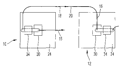
Fig. 1 shows a side view of a system using two welding wire containers with
covers according to the invention;
Fig. 2 shows a side view of the system of Fig. 1;

CA 02547857 2006-06-O1
WO 2005/061168 PCT/EP2004/014554
4
Fig. 3 shows in an enlarged view a container according to a first embodiment
of the invention;
Fig. 4 shows a perspective view of the cover shown in Fig. 3;
Fig. 5 shows a top view of a cover according to a second embodiment of the
invention; and
Fig. 6 shows a top view of a cover according to a third embodiment of the
invention.
Fig. 1 shows a first welding wire container 10 and a second welding wire
container 12. Both welding wire containers contain a coil 14 of welding wire
16.
The end portion 18 of the welding wire contained in the first container 10 is
joined
by a butt welding to the beginning or front portion 20 of the welding wire
coil
contained in the second container 12. The welding wire 16 is withdrawn from
the
welding wire containers 10, 12 through a feeding system 22 which is only
schematically depicted.
On top of each container 10, 12 a cover 24 (see also Figs. 3 and 4) is
arranged.
Each cover has an upper surface 26 which closes an upper opening of the
respective container, and side walls 28 extending from the upper surface 26
and
positioning the cover on the respective container.
In the center of the upper surface 26, a truncated pyramid 30 is provided.
Further, a slot 32 is provided in the upper surface 26. The slot 32 extends
from an
edge of the cover 24 towards and beyond the center of the upper surface 26. As
can be seen in Figs. 3 and 4, the slot 32 extends over the left side surface
and the
upper surface of the truncated pyramid 30 and over almost the entire right
side
surface.
A spacing means 34 is provided on the upper surface of the cover. The spacing
means 34 divides the slot 32 into an inner portion 36 and an outer portion 38.
The
welding wire feed to the welding machine extends through the inner portion 36
of
slot 32, and the end portion of the welding wire coil connected to the forward
end

CA 02547857 2006-06-O1
WO 2005/061168 PCT/EP2004/014554
of the subsequent welding wire coil extends through the outer portion 38 of
the
slot 32.
The spacing means 34, in the preferred embodiment, is formed from a plastic
plate attached to the upper surface 26 of the cover 24 on one side of the slot
32
5 only. This attachment is schematically shown with reference numeral 40 in
Figs. 3
and 4.
During operation, the welding wire is withdrawn from the respective container
through the inner portion 36 of the slot. After the welding wire stored in the
respective container has been entirely used, only a small loop 42 of welding
wire
(please see Fig. 1) remains in the container. The spacing means 34 ensures
that the
welding wire portion leading to the subsequent welding wire container is held
spaced apart from the portion currently withdrawn from the container. This
prevents any entanglement and kinks in the welding wire. If the welding wire
is
continued to be withdrawn from the container, loop 42 bends spacing means 34
upwardly on the side opposite attachment 40 so that the welding wire entirely
escapes from the first container. The system then automatically continues to
withdraw the welding wire from the second container.
Figure 5 shows a cover in which the spacing means is formed from two
separate adhesive paper labels attached to the cover spaced from each other.
One
of the labels holds the end portion 18 of the welding wire in the outer
portion 38
of the slot 32, and a second label holds the wire portion currently withdrawn
in the
inner portion 36 of the slot. When the system is switching from the currently
used
container to the subsequently used container, the paper labels are ruptured so
as to
allow the welding wire to escape from the container through the slot.
Figure 6 shows a third embodiment which largely corresponds to the second
embodiment. In the third embodiment, the two labels are formed from a stronger
material such as plastic, leather or cardboard. In order to allow the welding
wire to
escape through the slot when switching from the currently used container to
the

CA 02547857 2006-06-O1
WO 2005/061168 PCT/EP2004/014554
subsequently used container, the labels are provided with a preformed cut
which
makes it easier for the welding wire to escape from the labels.

Dessin représentatif
Une figure unique qui représente un dessin illustrant l'invention.
États administratifs

2024-08-01 : Dans le cadre de la transition vers les Brevets de nouvelle génération (BNG), la base de données sur les brevets canadiens (BDBC) contient désormais un Historique d'événement plus détaillé, qui reproduit le Journal des événements de notre nouvelle solution interne.

Veuillez noter que les événements débutant par « Inactive : » se réfèrent à des événements qui ne sont plus utilisés dans notre nouvelle solution interne.

Pour une meilleure compréhension de l'état de la demande ou brevet qui figure sur cette page, la rubrique Mise en garde , et les descriptions de Brevet , Historique d'événement , Taxes périodiques et Historique des paiements devraient être consultées.

Historique d'événement

Description Date
Demande non rétablie avant l'échéance 2009-12-21
Le délai pour l'annulation est expiré 2009-12-21
Réputée abandonnée - omission de répondre à un avis sur les taxes pour le maintien en état 2008-12-22
Lettre envoyée 2007-08-03
Inactive : Correspondance - Transfert 2007-07-10
Inactive : Transfert individuel 2007-06-01
Inactive : Page couverture publiée 2006-08-15
Inactive : Lettre de courtoisie - Preuve 2006-08-15
Inactive : Notice - Entrée phase nat. - Pas de RE 2006-08-11
Demande reçue - PCT 2006-06-27
Exigences pour l'entrée dans la phase nationale - jugée conforme 2006-06-01
Demande publiée (accessible au public) 2005-07-07

Historique d'abandonnement

Date d'abandonnement Raison Date de rétablissement
2008-12-22

Taxes périodiques

Le dernier paiement a été reçu le 2007-11-07

Avis : Si le paiement en totalité n'a pas été reçu au plus tard à la date indiquée, une taxe supplémentaire peut être imposée, soit une des taxes suivantes :

  • taxe de rétablissement ;
  • taxe pour paiement en souffrance ; ou
  • taxe additionnelle pour le renversement d'une péremption réputée.

Veuillez vous référer à la page web des taxes sur les brevets de l'OPIC pour voir tous les montants actuels des taxes.

Historique des taxes

Type de taxes Anniversaire Échéance Date payée
Taxe nationale de base - générale 2006-06-01
TM (demande, 2e anniv.) - générale 02 2006-12-21 2006-11-06
Enregistrement d'un document 2007-06-01
TM (demande, 3e anniv.) - générale 03 2007-12-21 2007-11-07
Titulaires au dossier

Les titulaires actuels et antérieures au dossier sont affichés en ordre alphabétique.

Titulaires actuels au dossier
SIDERGAS SPA
Titulaires antérieures au dossier
CARLO GELMETTI
Les propriétaires antérieurs qui ne figurent pas dans la liste des « Propriétaires au dossier » apparaîtront dans d'autres documents au dossier.
Documents

Pour visionner les fichiers sélectionnés, entrer le code reCAPTCHA :


Pour visualiser une image, cliquer sur un lien dans la colonne description du document. Pour télécharger l'image (les images), cliquer l'une ou plusieurs cases à cocher dans la première colonne et ensuite cliquer sur le bouton "Télécharger sélection en format PDF (archive Zip)" ou le bouton "Télécharger sélection (en un fichier PDF fusionné)".

Liste des documents de brevet publiés et non publiés sur la BDBC .

Si vous avez des difficultés à accéder au contenu, veuillez communiquer avec le Centre de services à la clientèle au 1-866-997-1936, ou envoyer un courriel au Centre de service à la clientèle de l'OPIC.


Description du
Document 
Date
(aaaa-mm-jj) 
Nombre de pages   Taille de l'image (Ko) 
Description 2006-06-01 6 249
Dessins 2006-06-01 3 32
Dessin représentatif 2006-06-01 1 5
Revendications 2006-06-01 3 98
Abrégé 2006-06-01 1 54
Page couverture 2006-08-15 1 33
Rappel de taxe de maintien due 2006-08-22 1 110
Avis d'entree dans la phase nationale 2006-08-11 1 193
Demande de preuve ou de transfert manquant 2007-06-04 1 102
Courtoisie - Certificat d'enregistrement (document(s) connexe(s)) 2007-08-03 1 104
Courtoisie - Lettre d'abandon (taxe de maintien en état) 2009-02-16 1 174
Rappel - requête d'examen 2009-08-24 1 125
PCT 2006-06-01 3 97
Correspondance 2006-08-11 1 26