Sélection de la langue

Search

Sommaire du brevet 2548314 

Énoncé de désistement de responsabilité concernant l'information provenant de tiers

Une partie des informations de ce site Web a été fournie par des sources externes. Le gouvernement du Canada n'assume aucune responsabilité concernant la précision, l'actualité ou la fiabilité des informations fournies par les sources externes. Les utilisateurs qui désirent employer cette information devraient consulter directement la source des informations. Le contenu fourni par les sources externes n'est pas assujetti aux exigences sur les langues officielles, la protection des renseignements personnels et l'accessibilité.

Disponibilité de l'Abrégé et des Revendications

L'apparition de différences dans le texte et l'image des Revendications et de l'Abrégé dépend du moment auquel le document est publié. Les textes des Revendications et de l'Abrégé sont affichés :

  • lorsque la demande peut être examinée par le public;
  • lorsque le brevet est émis (délivrance).
(12) Demande de brevet: (11) CA 2548314
(54) Titre français: SUPPORT POUR DISPOSITIF DE DISTRIBUTION
(54) Titre anglais: SUPPORT FOR DISPENSING DEVICE
Statut: Morte
Données bibliographiques
(51) Classification internationale des brevets (CIB):
  • B67D 7/74 (2010.01)
(72) Inventeurs :
  • BERTUCCI, MICHAEL H. (Etats-Unis d'Amérique)
  • LANG, CHRISTOPHER F. (Etats-Unis d'Amérique)
(73) Titulaires :
  • JOHNSONDIVERSEY, INC. (Etats-Unis d'Amérique)
(71) Demandeurs :
  • JOHNSONDIVERSEY, INC. (Etats-Unis d'Amérique)
(74) Agent: FINLAYSON & SINGLEHURST
(74) Co-agent:
(45) Délivré:
(86) Date de dépôt PCT: 2004-12-17
(87) Mise à la disponibilité du public: 2005-07-14
Licence disponible: S.O.
(25) Langue des documents déposés: Anglais

Traité de coopération en matière de brevets (PCT): Oui
(86) Numéro de la demande PCT: PCT/US2004/042658
(87) Numéro de publication internationale PCT: WO2005/063610
(85) Entrée nationale: 2006-06-06

(30) Données de priorité de la demande:
Numéro de la demande Pays / territoire Date
10/707,533 Etats-Unis d'Amérique 2003-12-19
10/710,306 Etats-Unis d'Amérique 2004-07-01

Abrégés

Abrégé français

La présente invention a trait à un appareil (10) pour le support d'un dispositif de distribution de liquide tenu à la main (12) qui assure une capacité de stockage pour le dispositif ainsi que le remplissage de récipients (33) et de godets. Dans un mode de réalisation préféré, l'appareil (10) assure le support de deux dispositifs de distribution (12) et le remplissage de deux récipients (33) ou d'un récipient et d'un godet. Dans un autre mode de réalisation préféré, l'appareil fournit deux supports (18) pour le dispositif de distribution et un support (27) pour un récipient.


Abrégé anglais


An apparatus (10) for supporting a hand held liquid dispensing device (12)
which affords a storage capability for the device as well as affords the
filling of containers (33) and buckets. In a preferred manner the apparatus
(10) provides for the support of two dispensing devices (12) and the filling
of two containers (33) or one container and a bucket. In another preferred
manner, the apparatus provides for two supports (18) for the dispensing device
and one (27) for a container.

Revendications

Note : Les revendications sont présentées dans la langue officielle dans laquelle elles ont été soumises.


7
WHAT IS CLAIMED IS:
1. An apparatus for supporting a hand held liquid dispensing device
comprising:
a first support member for receiving a nozzle portion of the dispensing
device; and
a second support member for holding a container, the first and second
support members being spaced from each other in substantial axial alignment
and
connected to a frame member for connection to a supporting structure.
2. The apparatus as defined in Claim 1 wherein the first support member
includes a cavity.
3. The apparatus as defined in Claim 1 wherein the second support
member is pivotably connected to the frame member.
4. The apparatus as defined in Claim 1 wherein there are two oppositely
disposed first support members connected to the frame member.
5. The apparatus as defined in Claim 1 wherein the first support member
is defined by a platform having a cavity for placement of a dispenser nozzle
therein.
6. The apparatus as defined in Claim 1 wherein the second support
member is defined by a foot portion, the foot portion supported by the frame
and
pivotally connected to the frame member.
7. The apparatus as defined in Claim 6 wherein the foot portion includes
a concave portion for receiving a bottle.


8


8. The apparatus as defined in Claim 1 wherein there are two oppositely
disposed second support members connected to the frame member, the frame
member
defined by a first portion extending in a first direction and a second portion
extending
essentially at right angles to the first portion, the second portion connected
to the two
oppositely disposed second support members.
9. The apparatus as defined in Claim 8 wherein the frame member is
composed of rod members.
10. The apparatus as defined in Claim 1 wherein the cavity includes a
passage constructed and arranged to permit passage of the nozzle portion
therethrough.
11. A combined hand held liquid dispensing device and apparatus for
supporting the device comprising:
a liquid dispensing device;
a first support member receiving a nozzle portion of the dispensing
device; and
a second support member for holding a container, the first and second
support members being spaced from each other in substantial axial alignment
and
connected to a frame member for connection to a supporting structure.
12. The apparatus as defined in Claim 11 wherein the first support member
includes a cavity.
13. The apparatus as defined in Claim 11 wherein the second support
member is pivotably connected to the frame member.
14. The apparatus as defined in Claim 11 wherein there are two oppositely
disposed first support members connected to the frame member.
15. The apparatus as defined in Claim 11 wherein the first support member
is defined by a platform having a cavity for placement of a dispenser nozzle
therein.


9

16. The apparatus as defined in Claim 11 wherein the second support
member is defined by a foot portion, the foot portion supported by the frame
and
pivotally connected to the frame member.
17. The apparatus as defined in Claim 16 wherein the foot portion includes
a concave portion for receiving a bottle.
18. The apparatus as defined in Claim 11 wherein there are two oppositely
disposed second support members connected to the frame member, the frame
member
defined by a first portion extending in a first direction and a second portion
extending
essentially at right angles to the first portion, the second portion connected
to the two
oppositely disposed second support members.
19. The apparatus as defined in Claim 18 wherein the frame member is
composed of rod members.
20. The apparatus as defined in Claim 11 wherein the cavity includes a
passage constructed and arranged to permit passage of the nozzle portion
therethrough.
21. An apparatus for supporting a hand held liquid dispensing device
comprising:
a first support member for receiving a nozzle portion of the dispensing
device; and
a second support member for holding a container, the first and second
support members being spaced from each other in substantial axial alignment
and
connected to a frame member for connection to a supporting structure, the
frame
member including a third support member for the dispensing device.
22. The apparatus as defined in Claim 21 wherein the frame member
includes a side portion connected to the third support member.


10
23. The apparatus as defined in Claim 22 wherein the side portion angles
inwardly in a direction from the third support member toward the first support
member.
24. The apparatus as defined in Claim 23 wherein the side portions are
constructed and arranged to accommodate containers of different sizes.
25. The apparatus as defined in Claim 21 wherein there are two oppositely
disposed first, second and third support members connected to the frame
member.
26. The apparatus as defined in Claim 21 wherein the second support
member is pivotally connected to the frame member.
27. The apparatus as defined in Claim 26 further including a funnel for
placement in the first support member.

Description

Note : Les descriptions sont présentées dans la langue officielle dans laquelle elles ont été soumises.


CA 02548314 2006-06-06
WO 2005/063610 PCT/US2004/042658
1
SUPPORT FOR DISPENSING DEVICE
CROSS-REFERENCE TO RELATED APPLICATIONS:
This application is a continuation-in-part of application Serial No.
10/707,533
filed on December 19, 2003.
STATEMENT REGARDING FEDERALLY SPONSORED RESEARCH OR
DEVELOPMENT:
None.
BACKGROUND OF .THE TNVENTION
Technical Field
This invention xelates to a support for a hand held dispensing device. More
particularly, it relates to a support for a hand held liquid dispensing device
which
includes a container support and facilitates the filling of a container as
well as affoxds
connection to a dispensing hose for filling a bucket.
The prior art does not provide a support or holder for hand held liquid
dispensing devices. There is a need for such an apparatus. The type of hand
held
liquid dispensing devices concerned with in this invention are those which are
attached to a hose and a container with liquid concentrate. Such, a device is
described
in U.S. Patent No. 6,708,901, which teachings are incorporated herein by
reference.
This type of dispenser dispenses cleaning, disinfectants and similar types of
materials.
After use, it is desirable to have a place to store the dispenser. It would
also be


CA 02548314 2006-06-06
WO 2005/063610 PCT/US2004/042658
desirable to have a stoxage apparatus which would also allow for the filling
of
containers and buckets with diluted concentrate while the dispenser is being
stored.
SUMMARY OF THE INVENTION
The present invention provides an apparatus for supporting a hand held liquid
dispensing device. The apparatus includes a first support member for receiving
a
nozzle portion of the dispensing device. There is a second support member for
holding a container, the fixst and second support members are spaced from each
other
in substantial axial alignment and connected to a frame member for connection
to a
supporting structure.
In a preferred embodiment, the first support member includes a cavity.
In another preferred embodiment, there are two oppositely disposed first
support membexs connected to the frame member.
In one aspect, the first support member is defined by a platform having a
cavity for placement of a dispenser nozzle therein and the second suppoxt
member is
defined by a foot portion, the foot portion supported by the frame and
pivotally
connected to the frame member.
In another aspect, there are two oppositely disposed second support members
connected to the frame member. The frame member is defined by a first portion
extending in a first direction and a second portion extending essentially at
right angles
to the first portion with the second portion connected to the two oppositely
disposed
second support members.
In still another aspect, the invention provides a combined hand held dispenser
device and apparatus for supporting the device.
In yet another aspect, the frame member includes a third support member as
well as a side portion connected to the third support member with the side
portion
angling inwardly from the third support member toward the first support
member.


CA 02548314 2006-06-06
WO 2005/063610 PCT/US2004/042658
3
The objects of some of the embodiments of the invention therefore are:
a) Providing an apparatus for storing and supporting a hand held liquid
dispensing apparatus;
b) Providing an apparatus for storing and supporting,a hand held liquid
dispensing apparatus which is easily utilized;
c) Providing an apparatus of the foregoing type which facilitates the
filling of containers;
d) Providing an apparatus of the foregoing type which can accommodate
two dispensing devices;
e) Providing an apparatus of the foregoing type which can be
economically manufactured;
f) Providing an apparatus of the foregoing type which affords a secure
holding of the dispensing apparatus;
g) Providing a temporary plumbed installation by mans of a water hose;
and
h) Providing bottle filling drip trays that fold up for bucket filling.
BRIEF DESCRIPTION OF THE DRAWINGS
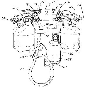
FIGURE 1 is a perspective view of the support for dispensing device of the
invention as well as two dispensing devices;
FIGURE 2 is a front view of the support for a dispensing device showing the
filling of a bucket;
FIGURE 3 is a top view of the support for a dispensing device;
FIGURE 4 is a front view of the support for a dispensing device without any
attachments;


CA 02548314 2006-06-06
WO 2005/063610 PCT/US2004/042658
FIGURE 5 is a side view of the support for a dispensing device;
FIGURE 6 is a bottom view of the support for a dispensing device;
FIGURE 7 is a front view with a portion shown in phantom illustrating the
supporting structure for the dispensing device;
FIGURE 8 is a perspective view of a second embodiment of the support for a
dispensing device;
FIGURE 9 is a front view of the embodiment shown in FfGURE 8 with a
dispensing device and bottle supported thereon; and
FIGURE 10 is a view similar to FIGURE 9 illustrating the connection of the
dispensing device to a hose.
DESCRIPTION OF THE PREFERRED EMBODIMENT
Refernng to FIGURES 1-4, the support apparatus generally 10 is illustrated in
conjunction with a dispensing device 12. The dispensing device was previously
referred to above as described in U.S. Patent No. 6,708,901. The support
apparatus
10 includes a platform 14 and a back wall 16, as well as cavities 18 which
receive the
",,.
spout 22 of the dispensing device 12. The platform 14 has indented panels 13
which
afford an area for placement of product identification labels to indicate the
materials
being dispensed from the dispenser bottle 55. There are also foot portions 25
and 27
which are pivotally attached to a frame 30 for purposes of supporting
containers such
as bottle 33 and provide a drip tray when a bottle is not present. These foot
portions
and 27 have indentations 35 so as to accommodate the bottoms of a bottle such
as
33. As seen in FIGURES 1 and 2, there is a hose 40 which is attached to the
dispensing tube 15 of dispenser 12 for the purpose of filling bucket 38.


CA 02548314 2006-06-06
WO 2005/063610 PCT/US2004/042658
Referring to FIGURES 5-7, it is seen that the frame 30 includes a portion 42
extending essentially at a right angle to the vertical portion 46 of frame 30.
This
portion 42 supports the foot portions 25 and 27 which they are pivotally
attached to
frame 30. As best seen in FIGURE 6, frame 30 includes an additional U-shaped
portion 44 supporting the platform 14 as by contact with the projections 48.
As seen
in FIGURE 7, there is connected to the frame 30 a cross-bar member 50
extending
behind the wall 16 through which mounting screws 52 can be inserted, such as
through the holes 53 as seen in FIGURE 4.
FIGURES 8-10 illustrate a second embodiment generally 10A of the support
apparatus. The same reference numerals are employed as previously with respect
to
similar elements and embodiment 10, except they include the "A" suffix. One of
the
differences between support apparatus 10 and 10A is the additional support
member
60A and the side portions 62A of the frame 30A. It should be noted that the
side
portions 62A angle inwardly in a direction from the third support member 60A
toward
I 5 the first support member in the form of platform 14A. This provides
additional
support for dispenser bottle 55A in addition to the support provided by the
spout 22A.
positioned in cavity 18A. Another difference is the funnel 64A. This affords
efficient
transfer of liquid material from the dispensing device 12A into the hose 40A
for
bucket filling.
Operation
A better understanding of the support apparatus 10 will be had by a
description of its operation. Referring to FIGURES 1 and 2, support apparatus
10 is
mounted to a wall such as by the mounting screws 52. Dispensing devices 12 are
supported by the support apparatus, such as by the placement of spouts 22 in
the
cavities 18. Water supply hoses (riot shown) are connected to the connectors
54 such
as by means of complementary discoimect devices (not shown). When it is
desired to
fill bottle 33, it is placed on foot portion 27. The bottle 33 can then be
easily filled
from the dispensing device 12 with a solution of the concentrate from the
dispenser
bottle 55 and the water. In the instance where it is desired to fill the
bucket 38, the
foot portion 25 is pivoted to an away position such as shown in FIGURE 2. This


CA 02548314 2006-06-06
WO 2005/063610 PCT/US2004/042658
affords a direct path for the hose 40 which is connected to the dispensing
tube I5 of
the dispensing device 12. In those instances where two bottles 33 are desired
to be
filled, foot portion 25 will assume a similar position as shown for foot
portion 27. In
a like manner, it will be supported by the frame portion 42.
The operation of support apparatus 10A is essentially the same as that
described for support apparatus 10. The major difference, as previously
described, is
the support of the bottle 55A by the support members 60A and the side portions
62A
and the presence of the funnel member 64A for bucket filling. In those
instances
where the bottle 55A is not of a size to rest on support member 60A, a smaller
bottle
would be supported by the angled side portions 62A.
It will thus be seen that there now is provided a supporting apparatus for
dispensing devices, such as 12, in a manner that they are not only
conveniently
supported in an out-of the-way position, but at the same time afford ease of
filling of
either a bottle 33 or a bucket 38.
The preferred material for fabricating platform 14, as well as foot portions
25
and 27 is polypropylene. However, other materials such as acetyl resins and
glass
filled polypropylene could also be employed. Frame member 30 is composed of a
steel bar with frame portion 42 being welded thereto as is portion 44 and the
bar
member 50. The preferred material for composing frame 30 is steel. However,
other
materials such as stainless steel and nylon could also be utilized. 'r
While the support apparatus 10 has been illustrated for use with the foot
portions 25 and 27 which could support two bottles 33 and alternatively
provide for a
connection support to the hose 40, it is readily apparent that the support
apparatus
could be designed for supporting only a single dispensing device and a single
container 33 placed on foot portion 27. When it is desired to fill a bucket 38
foot
portion 27 is moved to an upright position with connection to the hose 40 to
the
dispensing tube 15. AlI such and other modifications within the spirit of the
invention
are meant to be within its scope, as defined by the appended claims.

Dessin représentatif
Une figure unique qui représente un dessin illustrant l'invention.
États administratifs

Pour une meilleure compréhension de l'état de la demande ou brevet qui figure sur cette page, la rubrique Mise en garde , et les descriptions de Brevet , États administratifs , Taxes périodiques et Historique des paiements devraient être consultées.

États administratifs

Titre Date
Date de délivrance prévu Non disponible
(86) Date de dépôt PCT 2004-12-17
(87) Date de publication PCT 2005-07-14
(85) Entrée nationale 2006-06-06
Demande morte 2010-12-17

Historique d'abandonnement

Date d'abandonnement Raison Reinstatement Date
2009-12-17 Absence de requête d'examen
2010-12-17 Taxe périodique sur la demande impayée

Historique des paiements

Type de taxes Anniversaire Échéance Montant payé Date payée
Enregistrement de documents 100,00 $ 2006-06-06
Le dépôt d'une demande de brevet 400,00 $ 2006-06-06
Taxe de maintien en état - Demande - nouvelle loi 2 2006-12-18 100,00 $ 2006-12-01
Taxe de maintien en état - Demande - nouvelle loi 3 2007-12-17 100,00 $ 2007-12-03
Taxe de maintien en état - Demande - nouvelle loi 4 2008-12-17 100,00 $ 2008-12-02
Taxe de maintien en état - Demande - nouvelle loi 5 2009-12-17 200,00 $ 2009-12-01
Titulaires au dossier

Les titulaires actuels et antérieures au dossier sont affichés en ordre alphabétique.

Titulaires actuels au dossier
JOHNSONDIVERSEY, INC.
Titulaires antérieures au dossier
BERTUCCI, MICHAEL H.
LANG, CHRISTOPHER F.
Les propriétaires antérieurs qui ne figurent pas dans la liste des « Propriétaires au dossier » apparaîtront dans d'autres documents au dossier.
Documents

Pour visionner les fichiers sélectionnés, entrer le code reCAPTCHA :


Pour visualiser une image, cliquer sur un lien dans la colonne description du document. Pour télécharger l'image (les images), cliquer l'une ou plusieurs cases à cocher dans la première colonne et ensuite cliquer sur le bouton "Télécharger sélection en format PDF (archive Zip)" ou le bouton "Télécharger sélection (en un fichier PDF fusionné)".

Liste des documents de brevet publiés et non publiés sur la BDBC .

Si vous avez des difficultés à accéder au contenu, veuillez communiquer avec le Centre de services à la clientèle au 1-866-997-1936, ou envoyer un courriel au Centre de service à la clientèle de l'OPIC.


Description du
Document 
Date
(yyyy-mm-dd) 
Nombre de pages   Taille de l'image (Ko) 
Abrégé 2006-06-06 2 74
Revendications 2006-06-06 4 126
Dessins 2006-06-06 10 244
Description 2006-06-06 6 255
Dessins représentatifs 2006-08-16 1 20
Page couverture 2006-08-17 1 51
PCT 2006-06-06 4 132
Cession 2006-06-06 11 365