Sélection de la langue

Search

Sommaire du brevet 2549568 

Énoncé de désistement de responsabilité concernant l'information provenant de tiers

Une partie des informations de ce site Web a été fournie par des sources externes. Le gouvernement du Canada n'assume aucune responsabilité concernant la précision, l'actualité ou la fiabilité des informations fournies par les sources externes. Les utilisateurs qui désirent employer cette information devraient consulter directement la source des informations. Le contenu fourni par les sources externes n'est pas assujetti aux exigences sur les langues officielles, la protection des renseignements personnels et l'accessibilité.

Disponibilité de l'Abrégé et des Revendications

L'apparition de différences dans le texte et l'image des Revendications et de l'Abrégé dépend du moment auquel le document est publié. Les textes des Revendications et de l'Abrégé sont affichés :

  • lorsque la demande peut être examinée par le public;
  • lorsque le brevet est émis (délivrance).
(12) Brevet: (11) CA 2549568
(54) Titre français: CAPTEUR DE LIQUIDE OU DE GAZ ET PROCEDE ASSOCIE
(54) Titre anglais: LIQUID OR GAS SENSOR AND METHOD
Statut: Périmé et au-delà du délai pour l’annulation
Données bibliographiques
Abrégés

Abrégé français

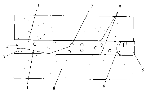
L'invention concerne un capteur de fluide contenant une cellule de fluide (1) renfermant un volume de fluide (7), c'est-à-dire un gaz ou un liquide, à analyser. L'invention concerne également un procédé de production d'un tel capteur. Le capteur de fluide comprend une source d'énergie électromagnétique (3) destinée à transmettre des ondes électromagnétiques (4) dans la cellule de fluide (1) et au moins un détecteur (5) qui détecte les ondes électromagnétiques traversant la cellule de fluide (1) et au moins une ouverture (2) pour l'admission/la sortie du fluide à analyser. Le capteur de fluide comporte en outre une carte de circuit imprimé (8, 10, 11, 12, 13, 14, 15, 16) pour évaluer l'intensité des ondes électromagnétiques atteignant lesdits détecteurs (5) et/ou pour fournir les circuits destinés à la source d'énergie électromagnétique (3). Au moins une partie de la cellule de fluide (1) est incorporée dans le substrat de la carte de circuit imprimé (8, 10, 11, 12, 13, 14, 15, 16).


Abrégé anglais


Fluid sensor containing a fluid cell (1) to enclose a volume of fluid (7),
i.e. a gas or liquid, that is to be analysed and a method for producing such a
fluid sensor. The fluid sensor comprises an electromagnetic energy source (3)
arranged to transmit electromagnetic waves (4) into the fluid cell (1) and at
least one detector (5) to detect electromagnetic waves passing through the
fluid cell (1) and at least one opening (2) for the inlet/outlet of a fluid
that is to be analysed. The fluid sensor also comprises a circuit board (8,
10, 11, 12, 13, 14, 15, 16) to evaluate the intensity of electromagnetic waves
reaching said at least one detector (5) and/or to provide the circuitry for
the electromagnetic energy source (3). At least part of the fluid cell (1) is
incorporated into the substrate of the circuit board (8, 10, 11, 12, 13, 14,
15, 16).

Revendications

Note : Les revendications sont présentées dans la langue officielle dans laquelle elles ont été soumises.


11
CLAIMS
1. Fluid sensor containing a fluid cell (1) to enclose a volume of fluid (7)
to be
analyzed, said fluid sensor comprising an electromagnetic energy source (3)
arranged to transmit electromagnetic waves (4) into the fluid cell (1), at
least one
detector (5) to detect electromagnetic waves passing through the fluid cell
(1) and
situated downstream of said energy source (3) along a straight line path of
said fluid
cell (1), at least one opening (2) for the inlet/outlet of fluid to be
analyzed, and a
circuit board (8, 10, 11, 12, 13, 14, 15, 16) to evaluate the intensity of
electromagnetic waves reaching said at least one detector (5) or provide the
circuitry
for the electromagnetic energy source (3) or both evaluate the intensity of
the
electromagnetic waves reaching said at least one detector (5) and provide the
circuitry for the electromagnetic energy source (3), at least part of the
straight- line
path of the fluid cell (1) being incorporated into the substrate of the
circuit board (8,
10, 11, 12, 13, 14, 15, 16).
2. Fluid sensor according to claim 1, which is a gas sensor.
3. Fluid sensor according to claim 1 or 2, wherein at least part of the
internal walls of
the fluid cell (1) are coated with a material (9) that is reflective to the
electromagnetic
waves (4) passing through the fluid cell (1).

12
4. Fluid sensor according to claim 3, wherein the material that is coated on
the
internal walls of the fluid cell is a metal.
5. Fluid sensor according to any one of claims 1 to 4, wherein the
electromagnetic
energy source (3), said at least one detector (5), or both of said
electromagnetic
energy source (3) and said at least one detector (5) is/are mounted on the
circuit
board (8, 10, 11, 12, 13, 14, 15, 16).
6. Fluid sensor according to any one of claims 1 to 5, wherein the
electromagnetic
energy source (3) is a light source and said at least one detector (5) is an
optical
detector.
7. Fluid sensor according to any one of claims 1 to 6, wherein the circuit
board of the
fluid sensor comprises a heat-generating component in the vicinity of the
fluid cell.
8. Fluid sensor according to any one of claims 1 to 7, wherein the fluid cell
extends
through the circuit board (8, 10, 11, 12, 13, 14, 15, 16), across the circuit
board, or
both through and across the circuit board.
9. Fluid sensor according to claim 1, wherein the fluid cell (1) is fully
embedded in
the substrate of the circuit board (8, 10, 11, 12, 13, 14, 15, 16).

13
10. Fluid sensor according to claim 1, wherein the fluid cell (1) extends
along a
surface of the circuit board (8, 10, 11, 12, 13, 14, 15, 16).
11. Fluid sensor according to claim 1, comprising a plurality of fluid cells
(1)
incorporated into the substrate of the circuit board (8, 10, 11, 12, 13, 14,
15, 16).
12. Fluid sensor according to claim 11, wherein the plurality of fluid cells
(1)
comprises at least one test channel to determine the attenuation at a
wavelength
not influenced by a fluid (7) to be analyzed, but close to the fluid (7), to
provide a
measure of the variation of the electromagnetic signal influenced by
environmental
parameters and not by the analyzed fluid.
13. Fluid sensor according to claim 1, comprising a flexible circuit board (8,
10, 11,
12, 13, 14, 15, 16).
14. A fluid sensor according to any one of claims 1 to 8, structured and
arranged for
determining the concentration of a gas or liquid (7).
15. A fluid sensor according to any one of claims 1 to 8, structured and
arranged for
determining the concentration of carbon dioxide in the exhaled air of a person
or a
person's breathing frequency.
16. A fluid sensor according to claim 1 which is a trace gas or liquid meter.

14
17. A fluid sensor according to claim 1, structured and arranged for
determining the
pressure, structure or composition of a gas or liquid.
18. A fluid sensor according to claim 1, wherein said fluid cell (1) extends
entirely
across the circuit board (8, 10, 11, 12, 13, 14, 15, 16) with said at least
one opening
(2) adjacent an edge of the circuit board (8, 10, 11, 12, 13, 14, 15, 16) and
said
detector (5) situated in an opening through an opposite edge of the circuit
board (8,
10, 11, 12, 13, 14, 15, 16).
19. Method for producing a fluid sensor having a fluid cell (1), comprising
the step
of: forming a straight trench having at least one substantially smooth surface
in the
substrate of a circuit board (8, 10, 11, 12, 12, 14, 15, 16) which will
constitute at
least part of a fluid cell; and positioning at least one detector (5) to
detect
electromagnetic waves (4) passing through the fluid cell (1) and situated
directly
downstream of an energy source (3) in said straight trench.
20. Method according to claim 19, comprising the further step of coating at
least part
of the, or each, wall of the trench with a material (9) that is reflective to
the
electromagnetic waves (4) that pass through the fluid cell (1).
21. Fluid sensor according to claim 4, wherein the metal is gold.

15
22. Fluid sensor according to claim 4, wherein the metal is silver.
23. Fluid sensor according to claim 6, wherein the light source is an infrared
light
source.
24. A fluid sensor according to claim 14, structured and arranged for
determining the
concentration of a gas or liquid having attenuation bands in the infrared
range.
25. A fluid sensor according to claim 14 structured and arranged for
determining the
concentration of carbon dioxide.
26. A fluid sensor according to claim 14 structured and arranged for
determining the
concentration of carbon monoxide.
27. A fluid sensor according to claim 14 structured and arranged for
determining the
concentration of a gas hydrocarbon.
28. A fluid sensor according to claim 14 structured and arranged for
determining the
concentration of nitrous oxide.
29. A fluid sensor according to claim 14 structured and arranged for
determining the
concentration of a liquid hydrocarbon.

16
30. Method according to claim 20, wherein the material is metal.
31. Method according to claim 19 or 20, wherein the step of forming the
straight
trench comprises selectively removing or displacing substrate material.
32. Method according to claim 19 or 20, wherein the step of forming the
straight
trench comprises forming the straight trench by laser.
33. Method according to claim 19 or 20, wherein the step of forming the
straight
trench comprises forming the straight trench by etching.
34. Method according to claim 19 or 20, wherein the step of forming the
straight
trench comprises forming the straight trench by drilling.

Description

Note : Les descriptions sont présentées dans la langue officielle dans laquelle elles ont été soumises.


CA 02549568 2006-06-13
WO 2005/059524 PCT/SE2003/002041
1
Liquid or gas sensor and method
TECHNICAL FIELD OF THE INVENTION AND PRIOR ART
The present invention concerns a fluid sensor, i.e. a sensor for a
gas or a liquid, such as a non-dispersive infrared (NDIR)-type
sensor, containing a fluid cell to enclose a volume of gas or
liquid that is to be analysed. The fluid sensor comprises an
electromagnetic energy source arranged to transmit
electromagnetic waves into the fluid cell and at least one
detector to detect electromagnetic waves passing through the
fluid cell and at least one opening for the inlet/outlet of gas that
is to be analysed. The gas sensor also comprises a circuit board
to evaluate the intensity of electromagnetic waves reaching said
at least one detector and/or to provide the circuitry for the
electromagnetic energy source. The present invention also re-
lates to a method for producing such a fluid sensor.
Gas sensors of the NDIR-type are well known in the art. Such
sensors comprise a gas cell with an IR-source at one end and
.an IR-detector, at the other. A gas containing molecules of the
gas that is to be analysed diffuse into the gas cell and IR-light is
directed through the gas cell towards the detector. The detector
has a filter in front of it which eliminates all light except the
specific wavelength that the gas that is to be analysed absorbs.
Since the other gas molecules in the gas cell do not absorb light
at that specific wavelength, only the molecules of the gas that is
to be analysed affect the amount of light reaching the detector.
The intensity of the light of the specific wavelength that reaches
the detector is therefore inversely proportional to the
concentration of the gas to be detected in the gas cell. The

CA 02549568 2006-06-13
WO 2005/059524 PCT/SE2003/002041
2
higher the concentration of such a gas, the more light of this
wavelength will be attenuated.
The gas cell of a gas sensor usually comprises a metal body
that is polished so as to reflect the light passing through the gas
cell. Alternatively the gas cell may be made of moulded or
extruded plastic components that are glued together and
sputtered with a material that is reflective to the electromagnetic
waves passing through the gas cell. The process of producing a
gas cell is therefore a relatively complex and expensive task and
requires special tools to produce the gas cell.
Furthermore, when such gas sensors are used condensation
collects on the inner walls of the gas cell which deteriorates the
quality of the signals passing through the gas cell and this can
adversely affect the analysis results.
SUMMARY OF THE INVENTION
The object of the present invention is to provide an accurate and
compact fluid sensor that is simple and inexpensive to construct.
This object is fulfilled using a fluid sensor, i.e. a gas sensor or a
liquid sensor, containing a fluid cell to enclose a volume of
liquid or gas that is to be analysed where the fluid cell has an
electromagnetic energy source arranged to transmit
electromagnetic waves into the fluid cell and at least one
detector to detect electromagnetic waves passing through the
fluid cell and at least one opening for the inlet/outlet of fluid, i.e.
liquid or gas, that is to be analysed. The fluid sensor comprises
a circuit board to evaluate the intensity of electromagnetic
waves reaching said at least one detector and/or to provide the
circuitry for the electromagnetic energy source. An array of
detectors is used if several gases are to be analyzed at the
same time.

CA 02549568 2006-06-13
WO 2005/059524 PCT/SE2003/002041
3
At least part of the fluid cell is incorporated into the substrate of
the circuit board i.e. the dielectric material on which the- circuit
is printed, etched or formed. By "at least part of the fluid cell" it
is meant at least part of an internal wall along which
electromagnetic waves will be transmitted.
According to a preferred embodiment of the invention at least
part of the internal walls of the fluid cell are coated with a
material that is reflective to the electromagnetic waves passing
through the fluid cell so as to reduce the attenuation of the
electromagnetic signal being transmitted through the fluid cell at
the cell walls. This means that the attenuation of the signal will
be, as far as possible, due only to its absorption by molecules of
the fluid being analysed. According to a preferred embodiment
of the invention the reflective material is a metal such as gold or
silver.
A fluid sensor always requires a circuit board to evaluate the
intensity of electromagnetic waves reaching said at least one
detector and/or to provide the circuitry for the electromagnetic
energy source and so a circuit board is a component that always
has to be manufactured for a fluid sensor. A circuit board is also
usually gold plated since gold is a good conductor and does not
corrode.
The circuit board may contain via-holes extending through the
whole or part of the circuit board to conduct current from one
part, or side, of the circuit board to another. These via holes are
holes going through the whole, or part, of the circuit board
substrate and are also usually gold plated and so are ideal for
use as a fluid cell. This means that it is relatively simple to
construct a fluid cell in the substrate of a circuit board and that
the time required to manufacture a fluid sensor can therefore be
significantly reduced as no special tools to manufacture the fluid
cell are required and the cost of producing a fluid sensor is
consequently significantly reduced. The inventive fluid sensor is

CA 02549568 2006-06-13
WO 2005/059524 PCT/SE2003/002041
4
more portable than a conventional fluid sensor as it is more
lightweight and compact than conventional fluid sensors which
have a separate fluid cell, usually made of metal. The inventive
fluid sensor may therefore be carried more easily.
Furthermore the condensation problem is decreased or
eliminated since the electric/electronic components mounted on
the circuit board generate heat which is conducted through the
substrate of the circuit board. As the walls of the fluid cell are
consequently heated this prevents condensation from collecting
on the inner walls of the of the fluid cell. According to a
preferred embodiment of the invention the circuit board of the
fluid sensor comprises a heat-generating component in the
vicinity of the fluid cell.
According to other preferred embodiments of the invention the
fluid cell extends through the circuit board and/or across the
circuit board, the fluid cell is either fully or partially embedded in
the substrate of the circuit board depending on the size of the
fluid cell and the thickness of the circuit board substrate. Part of
the fluid cell may, for example, extend along a surface of the
circuit board. The fluid cell may be completed using a metallized
capping part mounted on the surface of the circuit board.
According to another preferred embodiment of the invention the
electromagnetic energy source.and/or said at least one detector
is/are mounted on the circuit board so that the circuit board
provides the foundation for the whole fluid sensor however the
electromagnetic energy source and said at least one detector
may be provided as separate components in communication with
the fluid cell that is incorporated into the circuit board. However
mounting both of these components on the circuit board is
advantageous in that interconnecting wires or cables connecting
the components to the circuit board are not needed and this
eliminates the noise introduced by such interconnects,

CA 02549568 2006-06-13
WO 2005/059524 PCT/SE2003/002041
decreases the production time and makes the fluid sensor more
compact.
According to a further preferred embodiment of the invention the
5 electromagnetic energy source is a light source, such as an
infrared light source and said at least one detector is an optical
detector.
According to a preferred embodiment of the invention the fluid
cell is built up of a plurality of circuit boards stacked together.
One circuit board may for example contain one part of the fluid
cell and one or more circuit boards may be placed on, under or
beside the first circuit board so as to provide the complementary
part or parts of the fluid cell.
According to another preferred embodiment of the invention the
fluid sensor comprises a plurality of fluid cells incorporated into
the substrate of the circuit board. Having a plurality of gas cells
is advantageous if different sample gases are to be analyzed by
the fluid sensor simultaneously. The fluid cells may be arranged
so that a fluid may move freely between the fluid cells or from
one cell to the next in a specific order. According to another
preferred embodiment of the invention the plurality of fluid cells
comprises at least one test channel to determine the attenuation
at a wavelength not influenced by a fluid that is to be analysed,
but close to' it, to provide a measure of the variation of the
electromagnetic signal influenced by environmental parameters
and not by the analysed fluid.
According to a further preferred embodiment of the invention the
fluid sensor comprises a flexible circuit board that may be bent
into any desired shape.
The present invention also concerns a method for producing a
fluid sensor having a fluid cell. The method comprises the step
of forming a trench having at least one substantially smooth

CA 02549568 2006-06-13
WO 2005/059524 PCT/SE2003/002041
6
surface in the substrate of a circuit board along the path of the
intended fluid cell, which will constitute at least part of a fluid
cell. The expression "substantially smooth" is intended to mean
a surface that is smooth enough to substantially avoid the
introduction of distorted or spurious signals. Such a trench may
be formed by selectively removing or displacing the substrate
material with any technique known to those skilled in the art
such as by laser, by etching or drilling.
According to a preferred embodiment of the invention the
method comprises the further step of coating at least part of the,
or each, wall of the trench with a material that is reflective to the
electromagnetic waves that pass through the fluid cell, such as
a metal. This material may be applied by an electrolytic,
sputtering or any other suitable technique.
According to another preferred embodiment of the invention the
method comprises the further step of stacking a plurality of
circuit boards together so as to form a fluid cell.
The inventive fluid sensor is suitable for use in many
applications including determining the concentration of a gas
such as carbon dioxide, carbon monoxide, hydrocarbons, nitrous
oxide or a liquid such as a liquid hydrocarbon or any other gas
or liquid having attenuation bands in the infrared range. The
fluid sensor is suitable for use in medical equipment such as a
breathing monitor for determining the concentration of carbon
dioxide in the exhaled air of a person or a person's breathing
frequency or as a trace liquid or gas meter in ventilation and
alarm systems for example. The inventive fluid sensor is also
suitable for use to determine other properties of one or more
fluids in the fluid cell such as pressure, structure or
composition.

CA 02549568 2011-06-13
6a
According to another aspect of the invention, there is provided a fluid sensor
containing a fluid cell to enclose a volume of fluid, i.e. gas or liquid to be
analyzed,
said fluid sensor comprising: an electromagnetic energy source arranged to
transmit
electromagnetic waves into the fluid cell; at least one detector to detect
electromagnetic waves passing through the fluid cell and situated downstream
of
said energy source along a straight line path of said fluid cell; at least one
opening
for the inlet/outlet of fluid to be analyzed; and a circuit board to evaluate
the intensity
of electromagnetic waves reaching said at least one detector, provide the
circuitry
for the electromagnetic energy source, or both evaluate the intensity of the
electromagnetic waves reaching said at least one detector and provide the
circuitry
for the electromagnetic energy source; at least part of the straight line path
of the
fluid cell being incorporated into the substrate of the circuit board.
According to yet another aspect of the invention, there is provided a fluid
sensor
containing a fluid cell to enclose a volume of fluid), i.e. gas or liquid to
be analyzed,
said fluid sensor comprising: an electromagnetic energy source arranged to
transmit
electromagnetic waves into the fluid cell; at least one detector to detect
electromagnetic waves passing through the fluid cell; at least one opening for
the
inlet/outlet of fluid to be analyzed; and a circuit board to evaluate the
intensity of
electromagnetic waves reaching said at least one detector, provide the
circuitry for
the electromagnetic energy source, or both evaluate the intensity of
electromagnetic
waves reaching said at least one detector and provide the circuitry for the

CA 02549568 2010-07-14
6b
electromagnetic energy source; at least part of the fluid cell being
incorporated into
the substrate of the circuit board, and which is a liquid sensor.
According to a further aspect of the invention, there is provided a fluid
sensor
containing a fluid cell to enclose a volume of fluid, i.e. gas or liquid to be
analyzed,
said fluid sensor comprising: an electromagnetic energy source arranged to
transmit
electromagnetic waves into the fluid cell; at least one detector to detect
electromagnetic waves passing through the fluid cell; at least one opening for
the
inlettoutlet of fluid to be analyzed; and a circuit board to evaluate the
intensity of
electromagnetic waves reaching said at least one detector, provide the
circuitry for
the electromagnetic energy source, or both evaluate the intensity of
electromagnetic
waves reaching said at least one detector and provide the circuitry for the
electromagnetic energy source; at least part of the fluid cell being
incorporated into
the substrate of the circuit board; wherein the fluid cell is built up of a
plurality of
circuit boards stacked together.
According to yet another aspect of the invention, there is provided a method
for
producing a fluid sensor having a fluid cell, comprising the step of: forming
a straight
trench having at least one substantially smooth surface in the substrate of a
circuit
board which will constitute at least part of a fluid cell; and positioning at
least one
detector to detect electromagnetic waves passing through the fluid cell and
situated
directly downstream of an energy source in said straight trench.

CA 02549568 2010-07-14
6c
According to yet another aspect of the invention, there is provided a method
for
producing a fluid sensor having a fluid cell, comprising the step of forming a
trench
having at least one substantially smooth surface in the substrate of a circuit
board
which will constitute at least part of a fluid cell, and comprising the
further step of
stacking a plurality of circuit boards together to form a fluid cell.

CA 02549568 2006-06-13
WO 2005/059524 PCT/SE2003/002041
7
Further advantages as well as advantageous features of the in-
vention appear from the following description and the other de-
pendent claims.
BRIEF DESCRIPTION OF THE DRAWINGS
Fig. 1 is a schematic diagram of a gas sensor according to a
preferred embodiment of the invention, and
Fig. 2 shows part of a fluid sensor according to another
preferred embodiment of the invention, and
Fig. 3 shows part of a fluid sensor according to a further
preferred embodiment of the invention.
The following description and drawings are not intended to limit
the present invention to the embodiment disclosed. The
embodiments disclosed merely exemplify the principles of the
present invention. The components shown in the figures are not
drawn to scale.
DETAILED DESCRIPTION OF A PREFERRED EMBODIMENT
OF THE INVENTION
Figure 1 shows carbon dioxide sensor containing a gas cell 1 to
enclose a volume of gas, such as exhaled air from a person.
The gas cell comprises an opening 2 for the inlet/outlet of gas
that is to be analysed. The gas sensor comprises an IR-source
3, such as a heated element, arranged to transmit IR-radiation 4
into the gas cell and an IR-detector 5 to detect IR-radiation
passing through the gas cell. The gas cell therefore functions as
a waveguide for the IR-radiation.
A filter 6, is placed in front of the detector to eliminate all light
except the specific wavelength that carbon dioxide molecules 7

CA 02549568 2006-06-13
WO 2005/059524 PCT/SE2003/002041
8
absorb, namely 4.26 m, which is in the IR-range. The intensity
of 4.26 m light that reaches the detector 5 is inversely
proportional to the concentration of carbon dioxide in the sample
of gas in the gas cell. When the concentration of carbon dioxide
in the chamber is zero, the detector will detect the full light
intensity from the IR-source. The exact relationship between IR-
intensity and carbon dioxide concentration is determined by
calibrating the gas sensor with pure nitrogen and a known
concentration of carbon dioxide such as 5 vol% for example.
The gas cell 1 is incorporated into the substrate of a circuit
board 8. The substrate comprises a ceramic material, a polymer,
a composite or any other suitable dielectric material, and
electric/electronic components are mechanically supported and
electrically connected on the circuit board. A circuit board may
also comprise multiple dielectric layers sandwiched between
metal layers that are patterned to transfer signals between the
electronic components.
The gas cell 1 is for example formed in the via-hole of the circuit
board. The circuit board is used evaluate the intensity of IR-
radiation reaching the detector 5 and to provide the circuitry for
the IR-source 3. The inner walls of the gas cell are coated with
a material 9 that is reflective to the IR-radiation passing through
the gas cell 1;;:'which allows the IR-signal to be totally reflected
from one side of the gas cell to the other towards the IR-
detector and consequently results in lower transmission losses.
Such a gas sensor may also be used to determine the structure
or composition of a sample of gas in the gas cell.
Figure 2 shows a fluid cell 1 made up of three circuit boards
10,11,12, mounted on top one another. Circuit board 11, which
comprises electric/electronic components has a gold-plated
groove extending along the length of the circuit board which
provides the side walls of the fluid cell 1. Circuit boards 10 and

CA 02549568 2006-06-13
WO 2005/059524 PCT/SE2003/002041
9
12 provide the top and bottom walls of the fluid cell 1. Circuit
boards 10 and 12 could however be replaced with gold- or
silver-plated components placed above and below the groove in
circuit board 11 to provide the top and bottom walls of the fluid
cell 1.
The cross section of the fluid cell is rectangular in the example
shown, it can however have any geometrical form such as
circular, elliptical or square depending on the manufacturing
process. The width of the fluid cell may be chosen by the user
by varying the depth of the grooves. The optimal cross-sectional
dimension of the fluid cell depends on the frequency of the
electromagnetic waves being transmitted through the fluid cell
and the desired transmission mode. Fluid cells having improper
dimensions may distort the signal transmitted therethrough.
Although the fluid cell I extends through the circuit board 11 in
a straight line, the invention is not limited to such fluid cells. The
fluid cell 1 can have any geometrical form, it can be U-shaped
for example. Having a non-straight fluid cell geometry means
that a longer light absorption path can be created.
Figure 3 shows a fluid cell I with an elliptical cross-section
formed by stacking four circuit boards 13,14,15,16 on top of one
another for example by overlapping their via-holes. The length
of the fluid cell may therefore be varied by the user by choosing
the amount of circuit boards that are to be stacked in this way.
The fact that the fluid cell is easy to take apart also makes it
easier to clean. Another advantage is that such stackability
allows a multiparameter fluid sensor, for the analysis of several
gases or which incorporates several sensors, to be easily
constructed. The user can easily adapt the gas sensor to his/her
specific needs by choosing or varying the length of the fluid cell.
The invention is of course not in any way restricted to the pre-
ferred embodiments thereof described above, but many

CA 02549568 2006-06-13
WO 2005/059524 PCT/SE2003/002041
possibilities to modifications thereof would be apparent to a man
with ordinary skill in the art without departing from the basic
idea of the invention as defined in the appended claims.

Dessin représentatif
Une figure unique qui représente un dessin illustrant l'invention.
États administratifs

2024-08-01 : Dans le cadre de la transition vers les Brevets de nouvelle génération (BNG), la base de données sur les brevets canadiens (BDBC) contient désormais un Historique d'événement plus détaillé, qui reproduit le Journal des événements de notre nouvelle solution interne.

Veuillez noter que les événements débutant par « Inactive : » se réfèrent à des événements qui ne sont plus utilisés dans notre nouvelle solution interne.

Pour une meilleure compréhension de l'état de la demande ou brevet qui figure sur cette page, la rubrique Mise en garde , et les descriptions de Brevet , Historique d'événement , Taxes périodiques et Historique des paiements devraient être consultées.

Historique d'événement

Description Date
Inactive : CIB enlevée 2021-06-29
Inactive : CIB attribuée 2021-06-29
Inactive : CIB enlevée 2021-05-31
Inactive : CIB en 1re position 2021-05-31
Inactive : CIB attribuée 2021-05-31
Inactive : CIB enlevée 2021-05-31
Le délai pour l'annulation est expiré 2014-12-19
Inactive : CIB expirée 2014-01-01
Inactive : CIB enlevée 2013-12-31
Lettre envoyée 2013-12-19
Inactive : Regroupement d'agents 2012-03-07
Accordé par délivrance 2012-01-31
Inactive : Page couverture publiée 2012-01-30
Préoctroi 2011-11-08
Inactive : Taxe finale reçue 2011-11-08
Un avis d'acceptation est envoyé 2011-09-27
Lettre envoyée 2011-09-27
Inactive : Approuvée aux fins d'acceptation (AFA) 2011-09-19
Modification reçue - modification volontaire 2011-08-23
Inactive : Dem. de l'examinateur par.30(2) Règles 2011-07-26
Modification reçue - modification volontaire 2011-06-13
Inactive : Dem. de l'examinateur par.30(2) Règles 2011-02-01
Modification reçue - modification volontaire 2010-07-14
Inactive : Dem. de l'examinateur par.30(2) Règles 2010-01-22
Lettre envoyée 2008-10-03
Requête d'examen reçue 2008-08-28
Exigences pour une requête d'examen - jugée conforme 2008-08-28
Toutes les exigences pour l'examen - jugée conforme 2008-08-28
Inactive : Page couverture publiée 2006-08-25
Inactive : Notice - Entrée phase nat. - Pas de RE 2006-08-22
Lettre envoyée 2006-08-22
Demande reçue - PCT 2006-07-12
Exigences pour l'entrée dans la phase nationale - jugée conforme 2006-06-13
Demande publiée (accessible au public) 2005-06-30

Historique d'abandonnement

Il n'y a pas d'historique d'abandonnement

Taxes périodiques

Le dernier paiement a été reçu le 2011-11-22

Avis : Si le paiement en totalité n'a pas été reçu au plus tard à la date indiquée, une taxe supplémentaire peut être imposée, soit une des taxes suivantes :

  • taxe de rétablissement ;
  • taxe pour paiement en souffrance ; ou
  • taxe additionnelle pour le renversement d'une péremption réputée.

Les taxes sur les brevets sont ajustées au 1er janvier de chaque année. Les montants ci-dessus sont les montants actuels s'ils sont reçus au plus tard le 31 décembre de l'année en cours.
Veuillez vous référer à la page web des taxes sur les brevets de l'OPIC pour voir tous les montants actuels des taxes.

Historique des taxes

Type de taxes Anniversaire Échéance Date payée
TM (demande, 3e anniv.) - générale 03 2006-12-19 2006-06-13
Enregistrement d'un document 2006-06-13
TM (demande, 2e anniv.) - générale 02 2005-12-19 2006-06-13
Taxe nationale de base - générale 2006-06-13
TM (demande, 4e anniv.) - générale 04 2007-12-19 2007-12-03
Requête d'examen - générale 2008-08-28
TM (demande, 5e anniv.) - générale 05 2008-12-19 2008-12-05
TM (demande, 6e anniv.) - générale 06 2009-12-21 2009-12-03
TM (demande, 7e anniv.) - générale 07 2010-12-20 2010-12-07
Taxe finale - générale 2011-11-08
TM (demande, 8e anniv.) - générale 08 2011-12-19 2011-11-22
TM (brevet, 9e anniv.) - générale 2012-12-19 2012-12-19
Titulaires au dossier

Les titulaires actuels et antérieures au dossier sont affichés en ordre alphabétique.

Titulaires actuels au dossier
MEDAIR AB
Titulaires antérieures au dossier
JOHAN STENBERG
Les propriétaires antérieurs qui ne figurent pas dans la liste des « Propriétaires au dossier » apparaîtront dans d'autres documents au dossier.
Documents

Pour visionner les fichiers sélectionnés, entrer le code reCAPTCHA :


Pour visualiser une image, cliquer sur un lien dans la colonne description du document. Pour télécharger l'image (les images), cliquer l'une ou plusieurs cases à cocher dans la première colonne et ensuite cliquer sur le bouton "Télécharger sélection en format PDF (archive Zip)" ou le bouton "Télécharger sélection (en un fichier PDF fusionné)".

Liste des documents de brevet publiés et non publiés sur la BDBC .

Si vous avez des difficultés à accéder au contenu, veuillez communiquer avec le Centre de services à la clientèle au 1-866-997-1936, ou envoyer un courriel au Centre de service à la clientèle de l'OPIC.


Description du
Document 
Date
(aaaa-mm-jj) 
Nombre de pages   Taille de l'image (Ko) 
Description 2006-06-12 10 468
Revendications 2006-06-12 4 138
Dessins 2006-06-12 2 127
Abrégé 2006-06-12 1 120
Dessin représentatif 2006-08-23 1 99
Description 2010-07-13 13 566
Revendications 2010-07-13 7 210
Description 2011-06-12 13 565
Revendications 2011-06-12 6 150
Revendications 2011-08-22 6 151
Avis d'entree dans la phase nationale 2006-08-21 1 193
Courtoisie - Certificat d'enregistrement (document(s) connexe(s)) 2006-08-21 1 105
Rappel - requête d'examen 2008-08-19 1 118
Accusé de réception de la requête d'examen 2008-10-02 1 175
Avis du commissaire - Demande jugée acceptable 2011-09-26 1 163
Avis concernant la taxe de maintien 2014-01-29 1 171
PCT 2006-06-12 3 95
Correspondance 2011-11-07 2 67