Note : Les descriptions sont présentées dans la langue officielle dans laquelle elles ont été soumises.
CA 02550783 2006-06-21
WO 2005/065148 PCT/US2004/041468
METHOD, SYSTEM, AND COMPUTER PROGRAM PRODUCT FOR
AUTOMATICALLY MANAGING COMPONENTS WITHIN A
CONTROLLED ENVIRONMENT
BACKGROUND OF THE INVENTION
Field of the Invention
[0001] The present invention relates generally to a method for controlling
consumer electronic devices, and more specifically, to a method for
controlling consumer electronic devices through a sequence of command
operations that (i) can be defined to execute automatically at a particular
time
and/or upon the occurrence of a particular event, or (ii) can be automatically
particularized for application in a specific context.
Related Art
[0002] The dawn of the information age has revealed new and exciting
opportunities for computer processing capabilities. Personal computers have
been deployed in a variety of arenas to gain efficiencies, reduce cost, and
increase productivity. Miniaturization and portability have made personal
computers more accessible and a more valued tool in many business
environments. Personal computers have also become a very useful tool in non-
business environments, including educational institutions and homes.
[0003] Home computer networks are gaining increased popularity. Within a
home, multiple personal computers can be connected together to permit a user
to share files without having to manually carry a diskette from one room to
another. The computer network also permits the user to share printers, fax
machines, and other devices. Internet access facilities can also be provided
to
permit access to external networks and services. Thus, a user can operate a
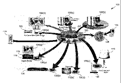
home computer to gain instant access to information from anywhere in the
world.
[0004] Despite the increasing presence of home computer networks, several
significant problems must be overcome. For example, installing a home
network can be time extensive and expensive to deploy. Additionally, there is
CA 02550783 2006-06-21
WO 2005/065148 PCT/US2004/041468
-2-
no easy method to integrate home computer networks with other residential
devices, such as televisions, stereos, DVD players, and other home
electronics.
Being able to efficiently distribute digital audio/video (AV) data among
personal computers and other AV devices (such as, televisions, DVD players,
PVRs, etc.) is complicated by differing and evolving communications
standards and/or formats. .
[0005] Another significant challenge is being able to effectively control the
networked residential devices. Although a remote control unit can be trained
to send signals to components of an entertainment center (such as, a
television,
stereo, and VCR), there is no known central device that can communicate and
control multiple personal computers and other analog and/or digital devices at
a residence. In addition, there is no known device that can communicate and
control multiple residential devices without user intervention. Even with a
remote control unit, a user must manually activate a hard key to send a
command (in the form of infrared signals) to a controllable CE device.
[0006] Although the combination of improved computer processing
capabilities and global access to information has resulted in significant
advancements in the information processing age, there exists a need for a
simple, inexpensive, yet versatile system that can integrate the functions of
multiple residential devices connected to a residential network and facilitate
the operations of these devices with minimal user intervention.
SUMMARY OF THE INVENTION
[0007] A method, system, and computer program product are provided to
manage a plurality of devices and/or applications within a controlled-
environment, such as a home, business, school, etc, as well as its surrounding
areas. A control center comprises one or more servers or other data processing
devices, and enables centralized command and control of the devices and/or
applications.
[0008] In embodiments of the present invention, a portable controller (such as
a personal digital assistant, wireless notepad, etc.) enables a user to
interact
CA 02550783 2006-06-21
WO 2005/065148 PCT/US2004/041468
-3-
with the control center. Such interaction includes altering the configuration
and performance of the other devices and/or applications. Accordingly, the
portable controller provides remote access to other devices and/or
applications, and enables the user to control their functions and/or
operations
from any location within the environment.
[0009] In an embodiment, the portable controller is a handheld platform
having a graphic display that has wireless connectivity to the control center
that controls the other devices and/or applications within the controlled
environment via a wireless network (e.g., as specified by IEEE standards
802.11a, 802.11b, 802.11g, etc.). In another embodiment, the control center is
built into the portable controller. In another embodiment, the portable
controller communicates directly with the other devices and/or applications
via infrared (IR) code signals.
[0010] In an embodiment, one or more control macros can be established to
control the operations and/or functions of the system components. A control
macro includes a set of commands that, when executed, enables the control
center to control multiple operations and/or functions of the system
components. The control macro (i.e., set of commands) can be associated with
a control macro filename for future recall and execution.
[0011] A user can define a control macro by operating the portable controller,
another computer client, or a user interface in communications with the
control center. In an embodiment, the control macro is stored at the portable
controller. When a user activates the control macro, the portable controller
sends a request to the control center, which, in turn, sends a sequence of
command signals to perform the requisite functions to produce a desired
outcome (such as, turning on a DVD player and an associated, television, and
instructing the DVD player to begin playing a DVD movie).
[0012] In another embodiment, the control macro is automatically executed
with little or no user intervention. The control macro is activated through a
sequence of command operations that can be defined to execute automatically
upon the occurrence of a commencement parameter, or can be automatically
CA 02550783 2006-06-21
WO 2005/065148 PCT/US2004/041468
-4-
particularized for application in a specific context. A commencement
parameter can be a predefined time, date, state, event, or the like, or any
combination thereof.
BRIEF DESCRIPTION OF THE DRAWINGS/FIGURES
[0013] The accompanying drawings, which are incorporated herein and form
part of the specification, illustrate the present invention and, together with
the
description, further serve to explain the principles of the invention and to
enable one skilled in the pertinent art(s) to make and use the invention. In
the
drawings, generally, like reference numbers indicate identical or functionally
or structurally similar elements. Additionally, generally, the leftmost
digit(s)
of a reference number identifies the drawing in which the reference number
first appears.
[0014] FIG. 1 illustrates a controlled system according to an embodiment of
the present invention
[0015] FIG. 2 illustrates tracking and/or monitoring system components
according to an embodiment of the present invention.
[0016] FIG. 3 illustrates commanding and/or controlling system components
in response to user location according to an embodiment of the present
invention.
[0017] FIG. 4 illustrates defining a control macro to watch a movie recording
according to an embodiment of the present invention.
[0018] FIG. 5 illustrates activating the control macro of FIG. 4 according to
an
embodiment of the present invention.
[0019] FIG. 6 illustrates defining an automatically executable control macro
according to an embodiment of the present invention.
[0020] FIG. 7 illustrates activating the automatically executable control
macro
of FIG. 6 according to an embodiment of the present invention.
[0021] FIG. 8 illustrates defining a context-based control macro according to
an embodiment of the present invention.
CA 02550783 2006-06-21
WO 2005/065148 PCT/US2004/041468
-5-
[0022] FIG. 9 illustrates activating the context-based control macro of FIG. 8
according to an embodiment of the present invention.
[0023] FIG. 10 illustrates a user interface for configuring a time-based
control
macro according to an embodiment of the present invention.
[0024] FIG. 11 illustrates a user interface for configuring a controllable
system component to execute a time-based control macro, according to an
embodiment of the present invention.
[0025] FIG. 12 illustrates a user interface for configuring an affiliate
controllable system component to execute a time-based control macro,
according to an embodiment of the present invention.
[0026] FIG. 13 is an example computer system useful for implementing the
present invention.
DETAILED DESCRIPTION OF THE INVENTION
TABLE OF CONTENTS
1. System Overview
II. Location Awareness
III. Profiling Portable Controller for Personalized Use
IV. Exemplary System Implementation
I. System Overview
[0027] The present invention is directed towards the centralized command and
control of a plurality of devices and/or applications within a controlled
environment, such as a residence, business, school, etc. A residential
controlled environment includes the confines of a home, apartment, mobile
home, houseboat, or other types of residences. However in embodiments, a
residential environment includes the surrounding area of the residence, as
well
as any shelters, constructs, improvements, or the like, within a designated
perimeter.
CA 02550783 2012-04-10
-6-
[0028] In other embodiments, the present invention is implemented in non-
residential environments. A non-residential environment includes, but is not
limited to, an office complex, suite of small offices, production studio,
warehouse, entertainment arena, school or university, health care facility,
hotel, vacation resort, aircraft, ship, automobile, or the like. In
embodiments,
the controlled environment for the non-residential embodiments include not
only the actual confines of the aforementioned structures but also their
surroundings within a designated perimeter.
[0029] Examples of a controlled environment are described in the application
entitled "Method, System, and Computer Program Product for Managing
Controlled Residential or Non-Residential Environments" (U.S. Patent App.
Serial No. 10/382,897), and the application entitled "Method, System, and
Computer Program Produce for Managing Controlled Residential or Non-
Residential Environments," (U.S. Patent App. Serial No. 10/180,500).
As described in these applications, various methods and systems
can be provided to manage the distribution of information (including video,
audio, voice, text, graphics, control messages, etc.) to the other devices
and/or
applications within the controlled environment. Such devices and/or
applications include, but are not limited to, communications equipment (such
as, telephones, intercoms, etc.), entertainment systems (such as, televisions,
CD/DVD players, gaming applications, stereos, etc.), monitoring systems
(such as, security cameras, baby monitors, etc.), safety/security systems
(such
as, fire alarms, sprinkler systems, locks on doors or windows, etc.), personal
computers (such as, desktops, notebooks, notepads, personal digital
assistants,
etc.), cooking appliances (such as, ovens, coffee makers, electrical
food/beverage warmers, etc.), comfort systems (such as, heating and air
conditioning (HVAC), humidifiers, dehumidifiers, air purifiers, light
switches,
light dimmers, etc.), power outlets, power supplies, or the like.
[0030] An example of such controlled environments are shown in FIG. 1,
which illustrates a residential controlled system 100 according to an
CA 02550783 2006-06-21
WO 2005/065148 PCT/US2004/041468
-7-
embodiment of the present invention. System 100 includes a communications
network 180 that interconnects a plurality of system components. The system
components include a positioning unit 102, two televisions 104 (shown as
television 104(a) and 104(b)), two computer clients 106 (shown as computer
client 106(a) and computer client 106(b)), one or more portable controllers
108, a lighting device 110, a thermostat 112 for a HVAC system, a tuner 114,
a media player 116, a cable box 118, a DSS box 120, and one or more central
servers 122. Other devices and/or applications can also be included as system
components.
[0031] Positioning unit 102 designates spatial locations within the residence
that serves as the hosting environment for system 100. Positioning unit 102 is
coupled to the other system components (e.g., portable controller 108) via a
wired and/or wireless interface. Positioning unit 102 is operable to designate
a
floor or room within the residence. Positioning unit 102 is also operable to
designate a specific location. or region within a floor or room. Moreover,
positioning unit 102 can be situated outside of the residence to thereby
designate external areas of the residence.
[0032] . Computer client 106 includes a wired and/or wireless personal
computer, personal digital assistant (PDA), enhanced telephone, personal
television, or other data processing device linked to communications network
180. As a personal computer, computer client 106 can be a desktop, notebook,
notepad, or the like. A display is coupled to computer client 106 to provide a
text or graphical user interface (GUI) and enable a user to interactively
communicate with server 122. Input devices for computer client 106 include a
keyboard, mouse, verbal command interface, mouse wheel, joystick, rudder
pedals, touch screen, microphone, joystick, stylus, light pen, or any other
type
of peripheral unit.
[0033] Portable controller 108 is a wired and/or wireless data processing
device that enables a user to interact with, send control messages to, and/or
manage the distribution of information (including audio, video, voice, and
other data) among the other system components. Portable controller 108 can
CA 02550783 2006-06-21
WO 2005/065148 PCT/US2004/041468
-8-
be a portable version of the devices listed as computer client 106. For
example, portable controller 108 can be a personal notebook or notepad
computer, PDA, enhanced telephone, or other device linked to
communications network 180 and including a display with the ability to
interact with the other system components. Hence, portable controller 108
enables a user to remotely control the operations of various components of
system 100. In an embodiment, the display for portable controller 108 is
capable of receiving video and/or audio from the other system components. In
an embodiment, portable controller 108 includes a flash ROM that enables
wireless downloads and/or uploads.
[00341 Television 104 is a conventional television. In an embodiment,
television 104 is enhanced to support interactive and/or personal services.
Personal services include virtual recording, programming, pausing/rewinding
live broadcasts, or the like. For example, television 104 can be a personal
television enhanced to support the MSN TV service, hosted by WebTV
Networks, Inc. (Mountain View, CA), that supports the WEBTV services
available from Microsoft Corporation (Redmond, WA). As shown, television
104 can be connected to cable set-top box 118, DSS set-top box 120, and/or
media player 116 (e.g., PVR, VCR, or DVD player).
[00351 One or more servers 122 police all traffic among the other system
components. The exchange of information among the system components is
routed or otherwise controlled via server 122. As such, server 122 interacts
with the other system components to directly or indirectly distribute data
(including audio and/or video), voice, and/or control messages over
communications network 180. In an embodiment, server 122 commands and
controls the operation and/or functions of one or more of the other system
components. The functions managed by server 122 includes video serving,
audio serving, telephony, messaging, file sharing, Internet access, and
security. According to embodiments of the present invention, a user operates
portable controller 108 to establish or re-configure these functions and/or
receive media from server 122 or other system components (either directly
CA 02550783 2006-06-21
WO 2005/065148 PCT/US2004/041468
-9-
from the other system components or indirectly from the system components
via server 122).
[0036] In an embodiment, portable controller 108 includes several functions
of server 122, as described herein, and manage the distribution of information
(including audio, video, voice, and other data) among the other system
components. In another embodiment, communications network 180 supports
peer-to-peer communications. As such, the system components exchange
audio, video, voice, other data, and/or control messages directly with each
other and without being centrally managed by server 122.
[0037] The aforementioned system components are not intended to be
exhaustive. Other devices (including appliances), applications, and/or the
like
can be implemented, including, but not limited to, a refrigerator, stove,
microwave, toaster, coffee-maker, alarm clock, humidifiers, sprinkler system,
lighting, light dimmers, etc. In an embodiment, server 122 and/or portable
controller 108 controls the operations and/or functions of such components,
such as on/off, timers, modulation (e.g., oven temperatures, etc.), pause,
snooze, etc.
[0038] As discussed, communications network 180 provides a transmission
medium for communicating among the system components. Communications
network 180 is a wired and/or wireless local area network (LAN). Thus,
communications network 180 includes wired, wireless, or both transmission
media, including satellite, terrestrial (e.g., fiber optic, copper, UTP, STP,
coaxial, hybrid fiber-coaxial (HFC), or the like), radio, microwave, free-
space
optics, and/or any other form or method of transmission.
[0039] In an embodiment using a wired transmission medium,
communications network 180 is an Ethernet LAN having a CAT-5 cable, or
the like, that is coupled to server 122 and distributed to a location within
each
room. In an embodiment, the cable is distributed to each system component,
such as television 104, media player 116, etc. The system component includes
an audio/video (AV) connector that is responsive to receive the cable. In an
embodiment, communications network 180 includes a telephone line and/or
CA 02550783 2006-06-21
WO 2005/065148 PCT/US2004/041468
-10-
powerline (such as, the communications technologies made available from the
Home Phone Networking Alliance (HomePNA) or the like).
[0040] In an embodiment using a wireless transmission medium,
communications network 180 supports the IEEE standard 802.11(a), which
specifies a wireless Ethernet protocol for large-sized video. In another
wireless embodiment, communications network 180 supports the IEEE
standard 802.11(b), which specifies a wireless Ethernet protocol for small-
size
video. In another wireless embodiment, communications network 180
supports the IEEE standard 802.11(g). In another embodiment, the
BLUETOOTHTM wireless technology (developed by Bluetooth SIG, Inc.) is
used to support short-range wireless interfaces with system 100.
[0041] As shown in FIG. 1, communications network 180 includes a wireless
network access point 182, such as those available from Linksys Group Inc.
(Irvine, CA) or Cisco Systems, Inc. (San Jose, CA), as a platform for the
system components. A wireless access point 182 provides a central point for
connectivity in a wireless network and always-on connectivity necessary for
tracking states of the system components. Additionally, a wireless access
point
182 can provide a connection point between a wired and wireless network. In
an embodiment using a server 122, as discussed above, a wireless access point
182 serves as a platform for the server 122. In alternative server-based
embodiments of the present invention, the server 122 can actually be located
on a number. of different device platforms in addition to a wireless access
point (such as, wireless access point 182 shown at 180), including a bridge
device (such as, bridges 130(a)-130(e)), a personal digital assistant (such
as,
108), a personal computer (such as, 106), or the like.
[0042] System 100 also includes a plurality of infrared/serial bridges 130(a)-
130(d), which comply with the IEEE 802.11(b) standard for wireless
communications. Each infrared/serial bridge 130 interacts with one or more
components. As shown, infrared/serial bridge 130(a) interacts with television
104(a), cable box 118, and media player 116. Infrared/serial bridge 130(b)
interacts with tuner 114 or any type of proprietary device that rely on
CA 02550783 2012-04-10
-11-
infrared/serial communication protocols as would be apparent to one skilled in
the relevant art(s). Infrared/serial bridge 130(c) interacts with thermostat
112.
Infrared/serial bridge 130(d) interacts with lighting device 110. A wireless-
Ethernet bridge 130(e) interacts with television 104(b) and a DSS box 120.
Wireless-Ethernet bridge 130(e) can support any IP addressable device. As
such, television 104(b) and DSS box 120 are "next generation" UPnP devices
that have IP addresses.
[0043] Therefore, the present invention can integrate legacy devices (e.g.,
consumer electronic (CE) devices that rely on infrared/serial communication
protocols), as well as UPNPTM devices and applications defined by the
Universal Plug and Play (UPnP) Forum, as system components. An example
of a controlled environment implementing an IEEE 802.11(b) infrared/serial
bridge is described in the application entitled "Legacy Device Bridge for
Residential or Non-Residential Networks" (U.S. Patent App. Serial No.
10/387,590; filed March 14, 2003).
[0044] As described above, portable controller 108 (such as, a digital
personal
assistant, wireless notepad, etc.) enables a user to remotely alter the
configuration and performance of other devices and/or applications from any
location within the controlled environment. In an embodiment, portable
controller 108 is a handheld platform having a graphic display that has
wireless connectivity to a central server 122 that can control the other
devices
and/or applications within a controlled environment via a wireless
communications network 180 (e.g., as specified by IEEE standard 802.11b).
In another embodiment, the server 122 is built into portable controller 108.
In
another embodiment, portable controller 108 communicates directly with the
other devices and/or applications via infrared (IR) code signals.
[0045] In an embodiment, the present invention facilitates control of a system
comprising an output system component (e.g., a television, a monitor, a
speaker, etc.) having multiple input system components (e.g., DVD, VCR,
satellite tuner, digital video recorder, stereo, etc.). In accordance with the
CA 02550783 2012-04-10
-12-
present invention, the user first selects the output component via the GUI
presented on portable controller 108. The user is then presented with a
control
screen affording the user with the ability to select a specific input
component
using a "tabbed" interface. When that input is selected, the control screen
for
that component is presented. Examples of user interfaces for associating and
controlling various system components are described in the application
entitled "User Interface for Multi-Device Control" (U.S. Patent App. Serial
No. 60/516,302).
II. Location Awareness
[0046] In embodiments of the present invention, network control system 100
tracks and/or monitors the positions of various system components (herein
referred to as the "target components") in real time or near term. As a user
migrates within the controlled environment that hosts system 100, the present
invention can implement several protocols to enable system 100 to determine
a location of a target component and hence, the location of the user in
communications with the target component. In an embodiment, a control
center (e.g., server 122, a local processor coupled to the target component,
etc.) determines the current location of the target component (e.g., portable
controller 108, etc.), and sends instructions to reconfigure the target
component to control other system components within a specified vicinity. For
example, if portable controller 108 is determined to be located within a
dining
area, server 122 enables portable controller 108 to be capable of controlling
system components positioned in the dining area. Such components can
include light dimmers, audio systems, heating units for food servers, or the
like.
[0047] Positioning units 102 are utilized in several embodiments for tracking
and/or monitoring target components. As described above with reference to
FIG. 1, one or more positioning units 102 are distributed throughout the
CA 02550783 2006-06-21
WO 2005/065148 PCT/US2004/041468
-13-
controlled environment that hosts system 100. The positioning units 102 can
be coupled to a target component (e.g., portable controller 108, an audio
client, telephone, etc.), or located as a stand-alone device within the
controlled
environment.
[0048] In an embodiment, positioning unit 102 is part of a RF
communications system. As such, a RF transponder interacts with a RF
interrogator to communicate positioning information. The transponder is
coupled to a system component and makes available identification information
that uniquely identifies the system component. The transponder can make
available other types of information, including an assigned location of the
system component if the component is a stationary or infrequently moved
device. Therefore, the transponder can be coupled to either the target
component or a positioning component (e.g., positioning unit 102).
[0049] The transponder can be active or passive. An active transponder
transmits a continuous or periodic signal containing the identification
information. A passive transponder remains inactive and/or silent until it is
activated by, for example, an interrogator, or manually activated by a user.
Therefore, the system component (that includes the transponder) can operate
in a silent mode or active mode. In active mode, the position of the system
component (i.e., the target component) is being tracked and/or monitored in
real time or near term. In silent mode, the current position of the system
component (i.e., the target component) is not known to system 100 with
absolute certainty until the transponder is activated.
[0050] The interrogator is coupled to another system component and receives
positioning information (e.g., identification information or the like) when it
comes within the communications range of a transponder. The interrogator
will automatically receive the positioning information from an active
transponder, or will activate a passive transponder to receive the positioning
information.
[0051] The interaction between a transponder and an interrogator is further
explained in the application entitled "Method, System, and Computer Program
CA 02550783 2006-06-21
WO 2005/065148 PCT/US2004/041468
-14-
Product for Managing Controlled Residential or Non-Residential
Environments" (U.S. Patent App. Serial No. 10/382,897), and the application
entitled "Method, System, and Computer Program Produce for Managing
Controlled Residential or Non-Residential Environments," (U.S. Patent App.
Serial No. 10/180,500). As discussed, various positioning technologies can be
implemented with the present invention for tracking and/or monitoring the
location of system components, including, for example, RF communications,
the BluetoothTM wireless technology (developed by Bluetooth SIG, Inc.), bar
coding technologies, GPS receivers, cellular signals, triangulation, or the
like.
[0052] In an embodiment, positioning can be realized without the use of
positioning unit 102. Portable controller 108, or the like, is responsive to
receive and process commands from the user operating portable controller
108. The commands are manually and/or verbally entered into portable
controller 108. Portable controller 108 processes the commands, or sends the
commands to server 122, to determine the location. For example, the user can
specify the location "living room," and the portable controller 108 would be
profiled to control devices and/or applications in the living room.
[0053] In another embodiment, however, voice and/or manual commands can
be entered into positioning unit 102 or the like. The user would also enter an
identifier for the target component (e.g., portable controller 108), and
position
unit 102 would send control signals to server 122, or the like, to update the
location records of target component.
[0054] As described above, the present invention supports various protocols
for gathering location information. The present invention provides several
methods and/or techniques for processing the location information to track
and/or monitor the position or movement of various components of system
100. Referring to FIG. 2, flowchart 200 represents the general operational
flow
of an embodiment of the present invention. More specifically, flowchart 200
shows an example of a control flow for tracking and/or monitoring system
components within a controlled environment.
CA 02550783 2006-06-21
WO 2005/065148 PCT/US2004/041468
-15-
[0055] Referring to FIG. 2, the control flow of flowchart 200 begins at step
201 and passes immediately to step 203. At step 203, an appropriate
component of system 100 accesses identification information or locator codes
that correspond to a system component (i.e., target component) that is being
tracked and/or monitored. Referring back to FIG. 1, the present invention can
determine the current position of any of the aforementioned system
components, including, but not limited to, positioning unit 102, television
104,
computer client 106, portable controller 108, lighting device 110, tuner 114,
media player 116, cable box 118, DSS box 120, server 122, a telephone, a
security camera, a security monitor, an audio client, and/or other devices
and/or applications. Additionally, as described above, the present invention
includes various embodiments for accessing locator codes. The locator codes
include an identifier for the transmitting or polled portable controller 110
or
other system component. The locator codes can also include other
identification codes or information for the polled or transmitting system
component. In an embodiment, the other identification information includes a
vicinity identifier, or the like, for the region (e.g., floor, room, etc.) of
the
residential environment where the transmitting or polled portable controller
108, positioning unit 102, or other system component, is located.
[0056] In an embodiment, a user interacts with a text or graphical interface
to
manually enter the current location for a target component. In another
embodiment, a voice command interface enables the user to enter voice
commands for a target component. As such, the user verbally communicates
the current location.
[0057] In another embodiment, a target component interacts with positioning
unit 102 to access locator codes. For example, the target component (e.g.,
portable controller 108, etc.) can be coupled to interrogator, which polls
positioning unit 102 for a vicinity identifier. The vicinity identifier
includes
locator codes for the current location for both system components.
[0058] - According to another example, the interrogator 406 can be integrated
with positioning unit 102. Hence, a target component (e.g., portable
controller
CA 02550783 2006-06-21
WO 2005/065148 PCT/US2004/041468
-16-
108, etc.) is polled by the interrogator. As a result, the interrogator
receives an
identifier for the polled target component. Locator codes are produced by
associating the identifier with the vicinity identifier for interrogator.
[0059] At step 206, the locator codes are sent to a command center for further
positioning processing. In an embodiment, the command center is server 122.
In another embodiment, the command center is at the target component (e.g.,
portable controller 108, computer client 106, etc.).
[0060] At step 209, the locator codes are matched to a region. The region can
be a specific floor, hallway, corridor, balcony, room, or the like. The region
can be a specific area within a floor, hallway, corridor, balcony, room, or
the
like. The region can also be a specific area within an external perimeter of
the
residence hosting system 100, or an adjoining or free-standing shelter on the
residential grounds.
[0061] At step 212, the current region is communicated to the target
component and/or stored in the records of server 122 for future recall. After
the system component has been positioned and its positioning data has been
updated, the control flow ends as indicated at step 295.
[0062] In an embodiment, the positioning information enables system 100 to
command and/or control specific system components based on the current
location of a user interacting with system 100. This can be described with
reference to FIG. 3. Flowchart 300, as illustrated in FIG. 3, represents the
general operational flow of an embodiment of the present invention. More
specifically, flowchart 300 shows an example of a control flow for
commanding and/or controlling system components based on a user's current
location.
[0063] Referring to FIG. 3, the control flow of flowchart 300 begins at step
301 and passes immediately to steps 203-209. As described with reference to
FIG. 2 at steps 203-209, locator codes enable system 100 to determine the
current location or region of a user interacting with a target component
(e.g.,
portable controller 108).
CA 02550783 2006-06-21
WO 2005/065148 PCT/US2004/041468
-17-
[0064] At step 312, a region profile is accessed for the region. The region
profile includes a listing of devices and/or applications (i.e., system
components) that receive commands and/or controls from server 122 and/or
portable controller 108 within a region.
[0065] At step 315, the region profile is processed to present control options
for the user to review. The control options include the listing of devices
and/or
applications corresponding to the region profile. As described with reference
to FIG. 2, the positioning can be determined remotely at server 122 or locally
at the target component (e.g., portable controller 108). If determined
remotely,
server 122, for example, produces and sends a user interface to display the
control options on the target component (e.g., portable controller 108 or
another system component the user is operating). If determined locally, the
target component (e.g., portable controller 108, etc.) retrieves the region
profile to produce the user interface. The region profile can be sent to the
target component on demand, or the target component can be updated
periodically with available region profiles.
[0066] At step 318, the user operates the target component (e.g., portable
controller 108, etc.) to send a request to control a system component (e.g.,
television 104, lighting device 110, etc.) that is identified in the region
profile.
The user can send a request to control a function and/or an operation of a
system component. The user can send a request to alter the configuration or
security profile for the component. Other control request can be sent as would
be apparent to one skilled in the relevant art(s).
[0067] At step 321, the control request is executed by the designated
component. The control request can be transmitted directly to the designated
component, or indirectly to the designated component via server 122. After the
control request has been executed, the control flow ends as indicated by step
395.
[0068] For example, if a user is operating portable controller 108 and is
determined by system 100 to be positioned in the "living room," portable
controller 108 would receive a user interface for controlling system
CA 02550783 2006-06-21
WO 2005/065148 PCT/US2004/041468
-18-
components in the living room. One system component can include, for
example, a security monitor that receives video input from a security camera
located at the front door to the residence. The user can interact with
portable
controller 108 to pan, tilt, or focus the security camera to display an image
on
the security monitor of a visitor standing at the front door. Another system
component can be television 104, and portable controller 108 can receive a
user interface for controlling the volume levels or channel selections for
television 104. The user can also interact with portable controller 108 to
alter
the settings of HVAC equipment (i.e., thermostat 112).
III. Profiling Portable Controller for Personalized Use
[0069] The present invention enables a user to operate portable controller 108
to command and/or control other system components. In an embodiment,
portable controller 108 only permits the user to control system components
within the vicinity of portable controller 108. In another embodiment,
portable
controller 108 provides the option of controlling system components in
another region.
[0070] In embodiments, control of the various system components is based on
preset profiles established for the user. The profiles can be generic for all
users
and/or specifically configured for a specific user. If configured for a
specific
user, the present invention utilizes various protocols to identify or
authenticate
a specific user and execute the profile established for the user. In an
embodiment, a username and/or password is entered into a system component
(e.g., portable controller 108, etc.). The password can be expressed by a
verbal
command, text, object, pixel, or the like. In another embodiment, biometrics
are collected by a system component. As such, retinal, iris, facial, palm,
fingerprint, and/or voice recognition technologies, or the like are
implemented
to identify and/or authenticate a user. In another embodiment, a user card is
read by a system component (e.g., portable controller 108, etc.). Other user
identification and/or authentication techniques can be used to identify and/or
CA 02550783 2006-06-21
WO 2005/065148 PCT/US2004/041468
-19-
authenticate a user. The present invention permits the user to alter the
profile,
as appropriate. The identification and/or authentication techniques, described
above, prevent other users from altering or deleting the user profile after it
has
been established.
[0071] In embodiments, the present invention enables a user to establish a
profile to store a "favorite" setting for the system components. For example,
a
favorite setting can be established for television programming, audio/video
recordings, room temperature, hot tub controls, clock alarms, light/dimmer
settings, web sites, news broadcasts, financial channels, or the like.
[0072] In embodiments, the user can establish a profile to create a
"playlist."
For example, a series of video or audio recordings can be prepared and/or
stored for playback on, for example, television 104 or an audio client. A
sequence of graphic images or photographs can be prepared and/or stored for
playback on, for example, a monitor or computer client 106. A playlist of
,other forms or media and/or multimedia can also be created according to
embodiments of the present invention, as would be apparent to one skilled in
the relevant art(s).
[0073] In embodiments, a profile can be created to establish a security
protocol for the system components. For example, a profile can be created to
block certain content from being accessed by designated users. Non-adult
users, for instance, can be prevented from accessing designated television
channels, web sites, areas (such as, lockable rooms, drawers, safes, etc.), or
the
like.
[0074] In embodiments, the present invention enables a single user to
establish multiple profiles. Each of the multiple profiles can be tailored for
context-sensitive activity. For instance, a user can create a profile for
evening
entertainment, which includes, without limitation, presets for lighting,
audio/video presentations, security access warnings, hot tub controls, or the
like. Another profile can be established for home office activities, which
includes, without limitation, presets for a baby monitor, a playlist of
classical
recordings, coffee maker . timer controls, or the like. A profile can be
CA 02550783 2006-06-21
WO 2005/065148 PCT/US2004/041468
-20-
established for morning rituals, which includes, without limitation, presets
for
alarm/snooze controls, coffee maker timer controls, lighting, news broadcasts,
or the like.
[0075] A user can also establish multiple profiles for use with other
individuals. For example, a user can have a profile with security controls set
to
block certain televisions programming, web sites, audio recordings, or the
like
when in the company of minors. However, when in the company of adults, the
user can recall another profile with more liberal security settings.
[0076] As such, the present invention enables various system components
(e.g., portable controller 108, etc.) to be user aware in addition to being
location aware. Thus for example, portable controller 108 can be customized
per user based on the aforementioned user profiles. In embodiments, the user
awareness functionality permits system 100 to implement "follow-me" system
controls. For instance, "follow-me" video is implemented to transfer a
selected
video production to various displays throughout the controlled environment.
The user would operate, for example, portable controller 108 to select a video
production (e.g., television show, DVD recording, or the like). The video
production can be presented on portable controller 108 (e.g., media viewer 710
described with reference to FIG. 7). As the user migrates from room to room
within the controlled environment, system 100 tracks portable controller 108
and retrieves a region profile for each region. Therefore, as the user enters
a
new region or room, a monitor or television 104 located in the room will
automatically start to display the video production selected by portable
controller 108.
[0077] Similarly, "follow-me" audio can be implemented by the present
invention. As such, the user can operate, for example, portable controller 108
to select an audio production (e.g., CD recording, radio broadcast, etc.). As
the
user migrates from room to room, the positioning techniques of the present
invention enable system 100 to transfer the audio production to audio clients,
monitors, or the like that are located in the vicinity of portable controller
108.
CA 02550783 2006-06-21
WO 2005/065148 PCT/US2004/041468
-21-
[0078] "Follow-me" lighting is another exemplary implementation of the
present invention. As a user, carrying portable controller 108, enters or
leave a
room, system 100 sends commands to dim or turn on/off the lights (e.g.,
lighting device 110 based on the profile settings.
[0079] In an embodiment, one or more control macros can be established to
control the operations and/or functions of the system components. A control
macro includes a set of commands that, when executed, enables server 122 to
control multiple operations and/or functions of one or more system
components. The control macro (i.e., set of commands) can be associated with
a control macro filename for future recall and execution.
[0080] A user can define a control macro by operating portable controller 108,
computer client 106, or a user interface in communications with server 122. In
an embodiment, a graphical user interface can be implemented to enable a user
to define a new control macro. FIG. 4 provides an example for defusing a
control macro according to an embodiment of the present invention. Flowchart
400 shows an example of a control flow for defining a control macro to watch
a movie recorded on DVD.
[0081] Referring to FIG. 4, the control flow of flowchart 400 begins at step
401 when the user triggers a record-macro command to distinguish the macro-
recording mode from normal system operations. At step 403, the user operates
one of the aforementioned devices (i.e., portable controller 108, computer
client 106, or a user interface to server 122) to select a room containing the
system component (e.g., television 104, monitor, etc.) that the user intends
to
use to view the movie.
[0082] At step 406, the region profile for the selected room is recalled. As.
discussed above, a region profile identifies all system components located in
a
designated region. In an embodiment, the region profiles are stored at server
122, which retrieves and makes the appropriate region profile available to the
user.
[0083] At step 409, the user reviews the region profile and selects a viewing
system component (e.g., television 104). The user also specifies the video
CA 02550783 2006-06-21
WO 2005/065148 PCT/US2004/041468
-22-
input for a DVD source (e.g., media player 116). The user can specify any
desired settings, including but not limited to, contrast, brightness, and the
like.
[00841 At step 412, the user specifies the desired audio settings. In an
embodiment, the user sets the volume level for the viewing system component
(e.g., television 104). In another embodiment, the user selects external
speakers or other audio clients to be used in addition to, or in lieu of, the
internal speakers for the viewing system component (e.g., television 104).
[00851 At step 415, the user selects the desired DVD movie from a DVD
player (i.e., media player 116). Alternatively, if the DVD player is located
in
the same room with the selected viewing system component (e.g., television
104), the user can instruct media player 116 to beginning playing the movie
currently loaded, or simply open the media bay and wait for the user to
manually insert the desired DVD.
[00861 At step 418, the user specifies the settings for lighting devices 110
denoted in the region profile. The user can dim the lighting to a desired
comfort level. In an embodiment, lighting device 110 includes the RadioRA
home dimming system available from Lutron Electronics Company, Inc.
(Coopersburg, PA). As such, the present invention enables the creation of
control commands for operating the RadioRA dimming system. Referring
back to FIG. 1, lighting device 110 is an exemplary lighting system that is
controlled by a signal repeater 1202 for a dimming system, such as Lutron's
RadioRA or X-10 dimming systems.
[00871 At step 421, the control commands for executing the specifications for
television 104, audio client 118 (if selected), media player 116, and lighting
device 110 are collectively associated with a common control macro.
[00881 At step 424, the user saves the control macro and gives it a filename,
such as "watch movie." In an embodiment using portable controller 108 to
create macro "watch movie," the user can associate the macro to a specific
macro button or icon. Therefore, when the user activates the "watch movie"
macro button, all of the associated commands for implementing the user's pre-
specified selections are recalled and executed, so that television 104 is
ready
CA 02550783 2006-06-21
WO 2005/065148 PCT/US2004/041468
-23-
to play the desired movie. After the control macro is created and saved, it is
ready for activation and the control flow ends as indicated at step 495.
[0089] In an embodiment, the commands associated with a specific control
macro are stored at server 122, or in a database or library affiliated with
server
122. Therefore, in an embodiment using portable controller 108 to execute a
control macro, portable controller 108 enables a user to associate a control
macro with a control macro button or icon. When executed, the control macro
button transmits a generic command to server 122. Server 122, in turn,
retrieves the set of commands associated the generic command, and transmits
the set of commands to the appropriate system components for execution. In
other words, the present invention enables a mobile device, such as portable
controller 108, to transmit a single high-level request to a centralized
command center, such as server 122. Server 122 interprets the single request
according to its environment (e.g., user, location) and finds the
corresponding
sequence of commands that needs to be transmitted over communications
network 180, which includes wireless (or powerline) communications.
[0090] Alternatively, according to an embodiment of the present invention, a
control macro can be created automatically by the server 122 based on the
particular devices and/or applications existing in a selected room or region,
either as known by server 122 through stored room profiles or as detected in
real time by server 122 as the room profile is created. For example, if server
122 detects that a room such as the living room has a DVD player (i.e., media
player 116) and a television 104, the control server will automatically build
a
basic "watch movie" macro comparable to the macro described above, which
can be further customized by the user.
[0091] FIG. 5 illustrates an example for activating a control macro according
to an embodiment of the present invention. Flowchart 500 shows a control
flow for activating the control macro of flowchart 400, which pertains to
watching a movie recorded on DVD.
CA 02550783 2006-06-21
WO 2005/065148 PCT/US2004/041468
-24-
[0092] Referring to FIG. 5, the control flow of flowchart 500 begins at step
501 and passes immediately to step 503. At step 503, the user activates the
"watch movie" control macro defined in steps 401-495.
[0093] At step 506, the set of commands associated with the "watch movie"
control macro is recalled from their storage location. The set of commands
includes the user-predefined specifications for controlling the functions
and/or
operations of the specified system components. In this example, the set of
commands associated with the "watch movie" control macro includes
commands for altering lighting device 110, activating media player 116, and
activating television 104. If the user desires to listen to the movie on a
home
stereo speaker system, the set of commands would also include commands for
activating the appropriate audio system component.
[0094] In an embodiment using portable controller 108 to activate the control
macro, portable controller 108 transmits a generic command that was
associated with the "watch movie" control macro. The generic command is
sent to server 122, which recalls the set of commands associated with the
generic command for the "watch movie" control macro.
[0095] At step 509, the room and system components (e.g., television 104 or
media player 116, lighting device 110, audio client) are identified from the
set
of commands. In the example described with reference to FIG. 4, the room is
specified in the control macro. However, in another embodiment, the control
macro, itself, does not need to be room specific. As discussed above, the
present invention includes methodologies and/or techniques for tracking the
location of a user or portable controller 108. Therefore, the user can request
to
activate a control macro (such as, the "watch movie" control macro) to watch
a movie in any room the user is currently located. As such, server 122 would
designate the user's current location as being the room for implementing the
control macro. Likewise, server 122 can retrieve the room profile for the
user's current location and identify the viewing components, media player,
and lighting components that are located in the designated room.
CA 02550783 2006-06-21
WO 2005/065148 PCT/US2004/041468
-25-
[00961 At step 512, device access permission is validated for each system
component identified at step 509. As discussed above, restrictions on
operating various system components can be established and policed by a
security protocol implemented by server 122. Accordingly, the present
invention provides methodologies and/or techniques for identifying or
authenticating the user that is requesting the "watch movie" control macro, as
well as for determining if the user is authorized to operate the system
components (including the actual DVD) designated in the control macro. If the
user is determined to lack authorization for accessing the designated system
components, a message can be sent to inform the user that access has been
blocked.
[0097] At step 515, the present invention determines which commands are
associated with each system component identified at step 509. For example,
the control commands for specifying the viewer settings are queued for
television 104. Similarly, the control commands for specifying the lighting
settings are queued for lighting device 110.
[0098] In an embodiment, server 122 apportions the component-specific
commands for each system component. The component-specific commands
are encoded and sent to the designated system component via the appropriate
protocol. Server 122 also updates its records for tracking the state of each
system component.
[0099] At step 518, each system component receives and executes the
component-specific commands. As such, the lighting (i.e., lighting device 110)
in the specified room is automatically dimmed, the specified television 104 is
turned-on and configured as predefined, and the specified DVD player (i.e.,
media player 116) is similarly activated. Depending on the speaker options
specified in the control macro, the identified audio component is also
activated
and waits to receive audio feed from the DVD player.
[0100] At step 521, a control screen is sent to the user interface that the
user
operated to activate the control macro. If portable controller 108 is used,
the
control screen is presented on the display to designate that the control macro
CA 02550783 2006-06-21
WO 2005/065148 PCT/US2004/041468
-26-
has been properly executed and the DVD movie is ready to commence playing
(or the DVD player is ready to receive the desired movie, if this option is
selected). Afterwards, the control flow ends as indicated at step 595.
[0101] As discussed above, when a user presses a particular key, on portable
controller 108, that has been assigned by the user to perform the basic "watch
movie" macro, portable controller 108 sends a request to a central network
server 122. The central server 122, in turn, has wireless network connectivity
to various CE devices via an 802.11/IR bridge 130. Therefore, upon receipt of
the "watch movie" request from portable controller 108, the server 122 sends a
sequence of command signals to perform a number of functions enabling the
user to watch a DVD (e.g., turning on the media player 116 and the associated
television 104 or monitor, and instructing media player 116 to begin playing
the DVD).
[0102] The present invention is not limited to a hard-key implementation. In
an embodiment, portable controller 108 is a PDA with a screen, which serves
as a wireless interface to central network server 122. In this embodiment,
upon
the user's activation of a "soft" "watch movie" macro button or icon on the
GUI for portable controller 108, the user's "watch movie" macro request is
forwarded to the server 122, which in turn sends the appropriate commands to
the television 104 and media player 116, both of which have networked
connectivity to the server 122. The advantage of the present invention is that
the user need not be in direct line-of-sight of the controllable devices,
which is
a requirement for a conventional IR remote control unit.
[0103] According to an embodiment of the present invention, a user must
physically commence the operation of a control macro by activation of the
hard or soft key on portable controller 108. In other embodiments of the
present invention, the control macro is automatically executed with little to
no
user intervention. The control macro is activated through a sequence of
command operations that (i) can be defined to execute automatically at a
particular time and/or upon the occurrence of a particular event, or (ii) can
be
automatically particularized for application in a specific context.
CA 02550783 2006-06-21
WO 2005/065148 PCT/US2004/041468
-27-
A. Time-Based Execution
[0104] In an embodiment of the present invention, a pre-defined sequence of
control commands is executed upon the occurrence of a pre-set time (i.e.,
clock based) and/or date (i.e., calendar based) automatically (i.e., without
direct user intervention). For example, the user may have a television 104 and
a satellite-TV tuner 114 in his or her bedroom. The user may desire to have
the bedroom television 104 automatically turned on and tuned to a particular
channel at 6:30 am as part of his or her "wake up" routine. This can be
achieved by a control macro consistent with the present invention.
[0105] Where the bedroom television 104 and lights 110 are connected via a
wireless network 180 to central server 122, central server 122 can be
programmed to power on the lights 110 and television 104 in the user's
bedroom at 6:30 am and tune the satellite-TV tuner 114 to the desired channel.
As discussed above, the user configures the control macro through a GUI that
can be generated by the central server 122 and displayed on the screen of
portable controller 108. The central server 122 can be a PC-based device that
is physically separate from portable controller 108, as shown in FIG. 1, or
the
central server 122 can reside in portable controller 108, itself.
[0106] In an embodiment in which portable controller 108 operates in a
standalone basis without server 122, an internal clock for portable controller
108 automatically initiates the control macro at 6:30 am, whereupon portable
controller 108 issues the appropriate command(s) either directly to the
respective controllable component (e.g., television 104), or indirectly the
controllable component via network access point 182 and/or bridges 130. The
user would, therefore, configure the control macro using a GUI generated by
portable controller 108.
[0107] Alternatively, a "wake-up" control macro can be configured to execute
only on certain days. For example, the user may only want the "wake-up"
control macro executed on weekdays. Thus, the user could program the
central server 122 or portable controller 108 to execute the "wake-up" control
macro on weekdays only.
CA 02550783 2006-06-21
WO 2005/065148 PCT/US2004/041468
-28-
[0108] FIG. 10 illustrates a user interface 1000 for configuring a time-based
control macro, according to an embodiment of the present invention. User
interface 1000 includes a configuration control field 1002, a name field 1004,
a time field 1006, a recurrence field 1008, a recurrence definition field
1010, a
controllable activity field 1012, and an acceptance activator 1014.
[0109] The configuration control field 1002 indicates the configuration level
for setting-up the time-based control macro. As shown in configuration
control field 1002, a "wake-up" control macro is being scheduled to occur
within the bedroom of a controlled environment, such as residential control
system 100.
[0110] Name field 1004 allows the user to personalize the name of the control
macro. In this example, the control macro is designated as "Wake Up."
[0111] Time field 1006 allows the user to specify the time for executing the
control macro. Recurrence field 1008 specifies whether the control macro will
repeat (i.e., a recurring event) or occur only once (i.e., a non-recurring
event).
The available selections for recurrence definition field 1010 is determined by
the input at recurrence field 1008. If recurrence field 1008 specifies a
recurring event, recurrence field 1010 allows the user to specify frequency of
recurrence. For example, the control macro can be scheduled to repeat on a
daily, bi-weekly, weekly, bi-monthly, monthly, or annual basis, or the like.
The control macro can be scheduled to execute only on weekends, week-days,
days having an even number, or designated holidays, birthdays, or
anniversaries, or the like. In an embodiment, fields are included to enable
the
user to designate a specific start and/or end date for executing the control
macro.
[0112] Controllable activity field 1012 allows the user to identify the
specific
event(s) which will occur upon execution of the control macro. For example,
the user can request that television 104 be powered-on and tuned to a specific
channel (shown in FIG. 10 as "Watch Cable TV"), request television 104 and
DVD player (e.g., media player 116) to be powered-on to watch a designated
movie (shown in FIG. 10 as "Watch DVD"), request a stereo to be powered-
CA 02550783 2006-06-21
WO 2005/065148 PCT/US2004/041468
-29-
on and tuned to a designated frequency channel (shown in FIG. 10 as "Listen
to Satellite Radio"), request the lighting 110 to be powered-on, request a
wake-up alarm, or the like.
[0113] The options for each field (e.g., time field 1006, recurrence
definition
field 1010, controllable activity field 1012, etc.) can be pre-defined and
presented in a drop-down menu, or the user can operate an input device to
manually enter the desired parameters.
[0114] Acceptance activator 1014 allows the user to finalize selections and
instruct central server 122 to accept the newly defined control macro. Once
the fields in user interface 1000 have been properly completed, the user can
operate an input device (such as, a mouse, stylus, finger, etc.) to touch
acceptance activator 1014, the input from user interface 1000 would be
processed by central server 122, and the next user interface, if appropriate,
would be presented.
[01.15] As shown in FIG. 10, "Watch Cable TV" is selected as the desired
activity in controllable activity field 1012. Therefore, the user would need
to
specify the primary and affiliate system components for executing the desired
activity. FIG. 11 illustrates a user interface 1100 for configuring a
controllable system component to execute a time-based control macro,
according to an embodiment of the present invention. As shown in
configuration control field 1002, television 104 is being configured to
execute
a "wake-up" control macro within a bedroom of the controlled environment
(e.g., residential control system 100).
[0116] User interface 1100 includes an input field 1104, an audio field 1103,
and a captions field 1108. Input field 1104 allows the user to specify the
input
source for the scheduled television event. As shown, the user has requested
input from a cable source (e.g., cable box 118). Other options include a
satellite feed from DSS box 120, over-the-air broadcast from tuner 114 or an
antenna coupled to television 104, media from media player 116 (e.g., PVR,
VCR, DVD, etc.), or the like.
CA 02550783 2006-06-21
WO 2005/065148 PCT/US2004/041468
-30-
[0117] Audio field 1106 allows the user to specify an audio level. The audio
level can be mute or at a predetermined decibel level.
[0118] Captions field 1108 allows the user to request text or captioning
options. Upon proper completion of the fields in user interface 1100, the user
can operate an input device (such as, a mouse, stylus, finger, etc.) to touch
acceptance activator 1014, the input from user interface 1100 would be
processed by central server 122, and the next user interface, if appropriate,
would be presented.
[0119] As shown in FIG. 11, "Cable" is selected as the desired input source
for television 104. Therefore, the user would need to configure an affiliate
system component to provide input to the primary system component
television 104, which, in this example, would specify a cable channel for
executing the desired activity. FIG. 12 illustrates a user interface 1200 for
configuring an affiliate controllable system component to execute a time-
based control macro, according to an embodiment of the present invention. As
shown in configuration control field 1002, a cable box 118 is being configured
to execute a "wake-up" control macro within 'a bedroom of the controlled
environment (e.g., residential control system 100).
[0120] User interface 1200 includes an channel field 1204, which allows the
user to specify the desired channel. Upon proper completion of channel field
1204, the user can activate acceptance activator 1014, and the input from user
interface 1200 would be processed by central server 122. Additional user
interfaces can be presented to enable the user to configure additional system
components, as appropriate.
B. State or Event-Based Execution
[0121] In an embodiment of the present invention, a pre-defined sequence of
control commands commences upon the occurrence of a particular event or the
occurrence of a particular system or component state. For example, a control
macro can be automatically executed when a system component (e.g., CE
device) is detected to be in a particular state (e.g., the television 104 in
the
family room has been powered on). As described in a pending patent
CA 02550783 2012-04-10
-31-
application entitled "Legacy Device Bridge for Residential or Non-Residential
Networks" (U.S. Patent App. Serial No. 10/387,590; filed March 14, 2003),
the on-off state of a
CE device can be determined through the use of a state detector. Such a state
detector can be as simple as a light-sensitive probe that is aimed at the
screen
for television 104, or can be functions as a basic on/off meter. When the
light-
sensitive probe senses the emission of light from the television 104 screen
(or,
alternatively, the change from red to green light on the LED power indicator
for television 104), the probe passes that information to the central server
122,
which determines that television 104 is in the "on" state.
[0122] Once the,server detects or determines that the family-room television
104 is in the "on" state, the server then automatically transmits the
appropriate
sequence of commands defining the desired control macro to the respective
system component. For instance, the server 122 could be programmed to
execute a "watch DVD movie" macro that includes dimming the family room
lights and activating the DVD/media player 116 once the television 104 is
powered on.-
[0123] In another embodiment of the present invention, the occurrence of a
particular detectable event (as opposed to state) can serve to prompt
automatic
execution of a pre-programmed macro. For example, a window (or door) can
be equipped with electrical/magnetic/optical sensors that are connected to the
central server 122 to inform the server 122 whether that window has been
opened. Upon detection of the kitchen window being opened, the server 122
can automatically execute a "security" control macro that would turn on the
lights 110 in the kitchen and/or activate the security alarm (i.e., the lights
110
and security alarm having network connectivity to the central server 122). Or,
for example, in response to a doorbell being activated (which doorbell has
connectivity to the central server 122), the server 122 can execute a control
macro that turns on the outside lights.
[0124] The control macro of the present invention can also be triggered in
response to a combination of states, events, and time. For example, the
CA 02550783 2006-06-21
WO 2005/065148 PCT/US2004/041468
-32-
"security" macro described above can be triggered only when the kitchen
window is opened (i.e., state) after 10:00 p.m. (i.e., time) on weekends
(i.e.,
date).
[0125] FIG. 6 provides an example for defining a control macro that is
activated upon occurrence of a "commencement" parameter, such as a
predefined time, date, state, event, or the like. Referring to FIG. 6, the
control
flow of flowchart 600 begins at step 601 when the user triggers a record-
macro command.
[0126] At step 603, the user operates one of the aforementioned devices (i.e.,
portable controller 108, computer client 106, a user interface to server 122,
or
the like) to establish a control macro to identify and specify the settings
for
one or more system components. For example, the user can configure several
audio-video devices to watch a movie as described above with reference to
steps 403-418 of FIG. 4. As another example, the user can configure a
bedroom light 110, television 104, and tuner 114 to create a "wake-up" control
macro as discussed above. The user can also configure the operations of an
alarm system, lights 110, security cameras, and monitors to define a
"security"
control macro as discussed above. The aforementioned examples are not
intended to be exhaustive. Other types of system components and
combinations of system components can be configured and associated with a
control macro as discussed herein.
[0127] As discussed above, in an embodiment, a control macro can be created
automatically by server 122. As such, at step 603, server 122 can setup a
control macro to, for example, watch a DVD by detecting the presence of the
appropriate system components within a selected room or region, either as
detected from a stored room profile or detected in real time as the room
profile
is created.
[0128] At step 606, the user specifies a commencement parameter that, when
activated, automatically enables the execution of the control macro specified
at step 603. As discussed above, a commencement parameter can be a
CA 02550783 2006-06-21
WO 2005/065148 PCT/US2004/041468
-33-
predefined time, date, state, event, or the like. The commencement parameter
can also be a combination of commencement parameters.
[0129] At step 609, the control commands for executing the specifications
from steps 603-606 are collectively associated with the control macro. At step
612, the control macro is given a filename and saved to a storage location. In
an embodiment using a portable controller 108 and central server 122, the
control macro is stored at the portable controller 108 and the associated
control commands are stored at central server 122. In another embodiment,
the control macro and the associated control commands are stored at server
122. In an embodiment that does not utilize a central server 122 (as discussed
above), both the control macro and associated control commands are stored at
the portable controller 108.
[0130] Afterwards, the control macro has been created and saved, the control
macro is ready for activation upon occurrence of the commencement
parameter(s), and the control flow ends as indicated at step 695.
[0131] FIG. 7 illustrates an example for activating an automatically
executable
control macro, according to an embodiment of the present invention.
Flowchart 700 show a control flow for activating the control macro of
flowchart 600.
[0132] Referring to FIG. 7, the control flow of flowchart 700 begins at step
701 and passes immediately to step 703. At step 703, the occurrence of a
commencement parameter is detected by portable controller 108, server 122,
or some other system component in communication with either portable
controller 108 or server 122. Upon detection of the occurrence of the
commencement parameter, at step 706, a control macro that has been
associated with the occurrence of the commencement parameter is accessed
and activated.
[0133] For example, the commencement parameter can be a predefined
date/time and component state. In other words, a user may setup a control
macro to activate a room light if the television 104 is turned-on after 8:00
p.m.
during the month of January. The commencement parameters, therefore,
CA 02550783 2006-06-21
WO 2005/065148 PCT/US2004/041468
-34-
would be a combination of day and time (i.e., between January 1-31 after 8:00
p.m.) and component state (i.e., television being powered-on). As such, if
someone turns on the television on during the month of January after 8:00
p.m., then at step 703, a state detector would signal the central server 122,
as
previously discussed. Thereafter, at step 706, control commands are sent to
activate the room light.
[0134] In an embodiment, user roles can be established and verified prior to
activating the control command, as discussed above at step 512. In other
embodiments, specific regions and/or controllable system components are
identified and commanded, discussed above at steps 509-521.
[0135] After the control macro has been automatically executed upon
occurrence of a predefined commencement parameter, the control flow ends as
indicated at step 795.
C. Context-Based Macros
[0136] As discussed above (with reference to step 509 of FIG. 5), a control
macro does not need to be room specific. In fact, according to an embodiment
of the present invention, a general control macro (e.g., "turn-TV-on" macro)
can be automatically particularized for use in a certain context (e.g., a
particular room). Unlike a control macro that is defined by a fixed,
predetermined sequence of commands, a "context-based" control macro of the
present invention is dynamic in the sense that the underlying commands are
different and automatically generated for each context in which it is applied.
[0137] As discussed above, a "watch DVD movie" macro can be established
and used to control a set of system components. Thus, a "watch DVD movie"
macro that has been specifically created for the family room entertainment
center (e.g., which may contain a SONY TV and PHILIPS DVD player) could
not be used in a bedroom containing a different set of system components
(e.g., RCA TV and SAMSUNG DVD player). Even if the user has a
"universal" remote capable of controlling all the televisions and DVD players
in the house, the user would still have to program different "watch DVD"
macros for each room's particular set of system components.
CA 02550783 2006-06-21
WO 2005/065148 PCT/US2004/041468
-35-
[01381 The present invention includes methodologies and/or techniques that
enable a user to program a general macro to control CE devices and other
system components for universal application in the user's home (e.g., system
100). In an embodiment, when the general macro is activated, the macro is
interpreted by a central server 122 (having network connectivity with the CE
devices and other system components) for purposes of executing the macro in
the context of the system components contained in a certain room. For
example, a user could program a general "watch DVD" macro (e.g., turn on a
television 104 and DVD/media player 116, and play a DVD movie) that can
be used for the entire house (e.g., system 100), regardless of whether the
system components vary from room to room.
[0139] As discussed above, a "location awareness" protocol enables the
central server 122 and/or portable controller 108 to detect what room a user
is
in for purposes of allowing the portable controller 108 to control the system
components in that room. Regarding the present invention, when the user
activates the general "watch DVD" macro in his or her family room, the
central server 122 interprets the general macro in the context of the room in
which the user is currently present (e.g., in the family room). Thus, the
central
server 122 would issue appropriate commands (e.g., turn on the SONY TV
and PHILIPS DVD player in the family room) corresponding to the general
"watch DVD" macro activated in the family room. Similarly, if the user
activated the same general "watch DVD" macro in his or her bedroom, the
central server 122 would detect the general macro being activated in the
bedroom, and send appropriate commands to the RCA TV and SAMSUNG
DVD player in the user's bedroom. In this manner, the user only needs to
program and maintain a single general "watch DVD" macro that can be used
for different sets of system components found throughout the controlled
environment.
[0140] Other examples of a context-based macro include a general "turn lights
on" macro that is automatically executed in the context of the room in which
it
was activated. Thus, according to the present invention, if the user activated
CA 02550783 2006-06-21
WO 2005/065148 PCT/US2004/041468
-36-
the "turn lights on' 'macro in the kitchen, the central server 122 would power
on only the lights in the kitchen. This way, the user need not program and
maintain a different "turn lights on" macro for each room of the house.
[0141] FIG. 8 provides an example for defining a context-based control macro
according to an embodiment of the present invention. Referring to FIG. 8, the
control flow of flowchart 800 begins at step 801 when the user triggers a
record-macro command.
[0142] At step 803, the user operates one of the aforementioned devices (i.e.,
portable controller 108, computer client 106, a user interface to server 122,
or
the like) to establish a general control macro to control the operations
and/or
functions of one or more system components. However, the user does not
specifically identify the system components, but rather specify the settings
for
a desired outcome. For example, referring to the "watch movie" example
described in FIG. 4, the user would specify the "type" of system components
that are needed to produce the desired outcome (i.e., watching a DVD
recording) and configure the settings therefor.
[0143] In an embodiment, a screen is presented to the user that only
identifies
the component type, such as a television 104 without reference to a specific
television 104. The user interacts with the screen to specify the desired
setting
for a television 104 as discussed above with reference to step 409, but the
specific device (e.g., SONY television in the family room) is not identified
in
the control screen. The user would complete similar component-type screens
to specify the desired settings of the other types of system components that
are
needed to produce the desired outcome. Referring back to FIG. 4, the other
types of system components would be an audio client, DVD/media player 116,
and lighting device 110. The settings for these types of system components
are established without identifying a specific component. Depending on the
desired outcome, other types of system components and combinations of
system components can be configured and 0061ssociated with a general
control macro as discussed herein.
CA 02550783 2012-04-10
-37-
[0144] In an embodiment, the user can specify a commencement parameter as
discussed above with reference to FIG. 6. As described above, the user can
program the general control macro to automatically execute upon occurrence
of one or more commencement parameters.
[0145] At step 806, the control commands for executing the specifications
from step 803 are associated with the general control macro. At step 809, the
general control macro is given a filename and saved to a storage location. In
an embodiment using a portable controller 108 and central server 122, the
general control macro is stored at the portable controller 108 and the
associated control commands are stored at central server 122. In another
embodiment, the general control macro and the associated control commands
are stored at server 122. In an embodiment that does not utilize a central
server 122 (as discussed above), both the general control macro and associated
control commands are stored at the portable controller 108.
[0146] Alternatively, the context-based control macro can be created
implicitly as the user defines the inter-relationship of system components by
entering information through a standard system/component setup process,
such as the process described in the application entitled "User Interface for
Multi-Device Control," (U.S. Provisional Serial No. 60/516,302).
For
example, for each desired user experience (e.g., watch DVD, watch satellite
TV, listen to CD, etc.), the user is requested to provide certain information,
including which system components need to be activated in connection with
that experience, what the settings are for each activated system component,
whether each system component has inputs (e.g., receivers, amps, televisions
104), what system components are connected to those inputs, etc. From this
information, a set of control scripts is generated for the particular user
experience. The commands in the script are triggered by actions on the user
interface for that experience. The commands in the script, in turn, invoke
system component-specific commands on the system components they act on
CA 02550783 2006-06-21
WO 2005/065148 PCT/US2004/041468
-38-
(e.g., activation of a "watch DVD" macro would invoke an "ON" command
for the television 104, and DVD player (e.g., media player 116).
[0147] After the general control macro has been created and saved, the control
macro is ready for activation, and the control flow ends as indicated at step
895.
[0148] FIG. 9 illustrates an example for activating a context-based control
macro, according to an embodiment of the present invention. Flowchart 900
shows a control flow for activating the control macro of flowchart 800.
[0149] Referring to FIG. 9, the control flow of flowchart 900 begins at step
901 and passes immediately to step 903.
[0150] At step 903, the general control macro defined in steps 801-895 is
activated. The control macro can be activated by a user operating portable
controller 108, or the control macro can be activated automatically upon
occurrence of a commencement parameter(s), as described in FIG. 7.
[0151] Referring back to FIG. 9, at step 906, the set of commands associated
with the general control macro is recalled from their storage location. The
set
of commands includes the user-predefined specifications for controlling the
functions and/or operations of the specified type(s) of system component(s).
In the "watch movie" example described in FIG. 4, the set of commands
associated with a "watch movie" general control macro includes commands
for altering a lighting device 110, activating a media player 116, activating
a
television 104, and activating an audio client, but the specific system
components are not identified in the commands.
[0152] At step 909, a specific region and one or more system components
(e.g., television 104 or media player 116, lighting device 110, audio client,
etc.) are identified for the set of commands. As discussed above with
reference to FIG. 4, the user can specify the region at the time of
establishing a
control macro. Also, as discussed above, the present invention includes
methodologies and/or techniques for tracking the location of a user or
portable
controller 108. Therefore, the user can request to activate a general control
macro to watch a movie in any region of the controlled environment 100 that
CA 02550783 2006-06-21
WO 2005/065148 PCT/US2004/041468
-39-
the user is currently located. As such, server 122 would designate the user's
current location as being the region for implementing the control macro. The
server 122 would also retrieve a region profile for the user's current
location
and identify the system components (e.g., media player 116, lighting devices
110, etc.) that are located in the designated region. In an embodiment, user
roles can be established and verified for each identified system component.
[0153] At step 912, the present invention determines which commands are
associated with each system component identified at step 909. At step 915,
each identified system component receives and executes the component-
specific commands. As such, referring back to the "watch movie" example,
the lighting (i.e., lighting device 110) in the specified region is
automatically
dimmed, the specified television 104 is turned-on and configured as
predefined, and the specified DVD player (i.e., media player 116) is similarly
activated. Depending on the speaker options specified in the control macro,
the identified audio component is also activated and waits to receive audio
feed. from the DVD player. After the context-based control macro has been
executed, the control flow ends as indicated at step 995.
IV. Exemplary System Implementation
[0154] FIGs. 1-12 are conceptual illustrations allowing an explanation of the
present invention. It should be understood that embodiments of the present
invention could be implemented in hardware, firmware, software, or a
combination thereof. In such an embodiment, the various components and
steps would be implemented in hardware, firmware, and/or software to
perform the functions of the present invention. That is, the same piece of
hardware, firmware, or module of software could perform one or more of the
illustrated blocks (i.e., components or steps).
[0155] Additionally, the present invention can be implemented in one or more
computer systems or other processing systems, capable of carrying out the
functionality described herein. Referring to FIG. 13, an example computer
CA 02550783 2006-06-21
WO 2005/065148 PCT/US2004/041468
-40-
system 1000 useful in implementing the present invention is shown. Various
embodiments are described in terms of this exemplary computer system 1300.
After reading this description, it will become apparent to a person skilled in
the relevant art(s) how to implement the invention using other computer
systems and/or computer architectures.
[0156] The computer system 1300 includes one or more processors, such as
processor 1304. Processor 1304 can be a special purpose or a general purpose
digital signal processor. The processor 1304 is connected to a communication
infrastructure 1306 (e.g., a communications bus, cross-over bar, or network).
[0157] Computer system 1300 can include a display interface 1302 that
forwards graphics, text, and other data from the communication infrastructure
1306 (or from a frame buffer not shown) for display on the display unit 1330.
[0158] Computer system 1300 also includes a main memory 1308, preferably
random access memory (RAM), and can also include a secondary memory
13 10. The secondary memory 1310 can include, for example, a hard disk drive
1312 and/or a removable storage drive 1314, representing a floppy disk drive,
a magnetic tape drive, an optical disk drive, etc. The removable storage drive
1314 reads from and/or writes to a removable storage unit 1318 in a well-
known manner. Removable storage unit 1318, represents a floppy disk,
magnetic tape, optical disk, etc. which is read by and written to removable
storage drive 1314. As will be appreciated, the removable storage unit 1318
includes a computer usable storage medium having stored therein computer
software (e.g., programs or other instructions) and/or data.
[0159] In alternative embodiments, secondary memory 1310 includes other
similar means for allowing software and/or data to be loaded into computer
system 1300. Such means include, for example, a removable storage unit 1322
and an interface 1320. Examples of such means include a program cartridge
and cartridge interface (such as that found in video game devices), a
removable memory chip (such as, an EPROM or PROM) and associated
socket, and other removable storage units 1322 and interfaces 1320 which
CA 02550783 2006-06-21
WO 2005/065148 PCT/US2004/041468
-41-
allow software and data to be transferred from the removable storage unit
.1322 to computer system 1300.
[01601 Computer system 1300 can also include a communications interface
1324. Communications interface 1324 allows software and/or data to be
transferred between computer system 1300 and external devices. Examples of
communications interface 1324 include a modem, a network interface (such as
an Ethernet card), a communications port, a PCMCIA slot and card, etc.
Software and data transferred via communications interface 1324 are in the
form of signals 1328 which can be electronic, electromagnetic, optical or
other
signals capable of being received by communications interface 1324. These
signals 1328 are provided to communications interface 1324 via a
communications path (i.e., channel) 1326. Communications path 1326 carries
signals 1328 and can be implemented using wire or cable, fiber optics, a phone
line, a cellular phone link, an RF link, free-space optics, and other
communications channels.
[01611 In this document, the terms "computer program medium" and
"computer usable medium" are used to generally refer to media such as
removable storage unit 1318, removable storage unit 1322, a hard disk
installed in hard disk drive 1312, and signals 1328. These computer program
products are means for providing software to computer system 1300. The
invention, in an embodiment, is directed to such computer program products.
[01621 Computer programs (also called computer control logic or computer
readable program code) are stored in main memory 1308 and/or secondary
memory 1310. Computer programs can also be received via communications
interface 1324. Such computer programs, when executed, enable the computer
system 1300 to implement the present invention as discussed herein. In
particular, the computer programs, when executed, enable the processor 1304
to implement the processes of the present invention, such as the method(s)
implemented using, for example, portable controller 108, server 122, and/or
other system components of system 100 described above, such as methods
CA 02550783 2012-04-10
-42-
200, 300, 400, 500, 600, 700, 800 and/or 900, for example. Accordingly, such
computer programs represent controllers of the computer system 1300.
[0163] In an embodiment where the invention is implemented using software,
the software can be stored in a computer program product and loaded into
computer system 1300 using removable storage drive 1314, hard drive 1312 or
communications interface 1324. The control logic (software), when executed
by the processor 1304, causes the processor 1304 to perform the functions of
the invention as described herein.
[0164] In another embodiment, the invention is implemented primarily in
hardware using, for example, hardware components such as application
specific integrated circuits (ASICs). Implementation of the hardware state
machine so as to perform the functions described herein will be apparent to
persons skilled in the relevant art(s).
[0165] In yet another embodiment, the invention is implemented using a
combination of both hardware and software.
[0166] While various embodiments of the present invention have been
described above, it should be understood that they have been presented by way
of example, and not limitation. It will be apparent to persons skilled in the
relevant art(s) that various changes in form and detail can be made therein
within the limits of the following claims. Moreover as
previously discussed, it should be understood that the method, system, and
computer program product of the present invention should not be limited to a
residential environment. The present invention can be implemented in other
types of environments having a central processing system for distributing
media and sending command and/or control signals to a plurality of devices
and/or applications dispersed throughout a designated region. In addition to a
residence, the designated region includes, but is not limited to, office
complexes, suite of small offices, production studios, warehouses,
entertainment arenas, health care facilities, hotels, vacation resorts,
aircrafts,
ships, automobiles, or the like. Thus, the present invention should not be
CA 02550783 2012-04-10
-43-
limited by any of the above-described exemplary embodiments, but should be
defined only in accordance with the following claims.