Sélection de la langue

Search

Sommaire du brevet 2552298 

Énoncé de désistement de responsabilité concernant l'information provenant de tiers

Une partie des informations de ce site Web a été fournie par des sources externes. Le gouvernement du Canada n'assume aucune responsabilité concernant la précision, l'actualité ou la fiabilité des informations fournies par les sources externes. Les utilisateurs qui désirent employer cette information devraient consulter directement la source des informations. Le contenu fourni par les sources externes n'est pas assujetti aux exigences sur les langues officielles, la protection des renseignements personnels et l'accessibilité.

Disponibilité de l'Abrégé et des Revendications

L'apparition de différences dans le texte et l'image des Revendications et de l'Abrégé dépend du moment auquel le document est publié. Les textes des Revendications et de l'Abrégé sont affichés :

  • lorsque la demande peut être examinée par le public;
  • lorsque le brevet est émis (délivrance).
(12) Brevet: (11) CA 2552298
(54) Titre français: TUBE AMORTISSEUR ET NECESSAIRE POUR AMORTISSEUR
(54) Titre anglais: SHOCK ABSORBER CRUTCH AND SHOCK ABSORBER KIT
Statut: Périmé et au-delà du délai pour l’annulation
Données bibliographiques
(51) Classification internationale des brevets (CIB):
  • A61H 03/02 (2006.01)
  • F16F 01/12 (2006.01)
(72) Inventeurs :
  • CHAPMAN, RICHARD ROBERT (Canada)
(73) Titulaires :
  • RICHARD ROBERT CHAPMAN
(71) Demandeurs :
  • RICHARD ROBERT CHAPMAN (Canada)
(74) Agent:
(74) Co-agent:
(45) Délivré: 2011-02-22
(22) Date de dépôt: 2006-07-12
(41) Mise à la disponibilité du public: 2007-12-06
Requête d'examen: 2009-10-30
Licence disponible: Oui
Cédé au domaine public: S.O.
(25) Langue des documents déposés: Anglais

Traité de coopération en matière de brevets (PCT): Non

(30) Données de priorité de la demande:
Numéro de la demande Pays / territoire Date
11/447,015 (Etats-Unis d'Amérique) 2006-06-06

Abrégés

Abrégé français

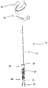
Il s'agit d'un tube amortisseur dans lequel un élément extensible peut coulisser à l'intérieur et à l'extérieur d'un corps principal, et qui est commandé par une action élastique. La présente divulgation traite aussi d'un jeu de conversion d'amortisseur. Ce jeu permet de convertir un tube constitué d'un corps principal tubulaire et d'un élément extensible fixé et ajusté à l'intérieur du corps principal. Le jeu comprend un premier contrefort pouvant être fixé au corps principal, un second contrefort pouvant être fixé à l'élément extensible et un dispositif élastique positionnable entre le premier et le second contrefort. De la sorte, la pression exercée sur le corps principal produit le mouvement télescopique de l'élément extensible dans le corps principal et contraint le dispositif élastique. Le relâchement de la pression assure le mouvement de l'élément extensible vers l'extérieur du corps principal et relâche cette contrainte.


Abrégé anglais

A shock absorber crutch in which an extension member is slidable into and out of a main body, and is controlled by a resilient action. Also disclosed is a shock absorber conversion kit, for converting a crutch of the type having a tubular main body and an extension member secured to and fitting within the main body, the kit having a first abutment attachable to the main body, a second abutment attachable to the extension member, a resilient device which can be positioned between the first abutment and second abutment, so that pressure on the main body will cause telescoping movement of the extension member into the main body and will stress the resilient device, and release of pressure will permit movement of the extension member out of the main body and will relax such stress.

Revendications

Note : Les revendications sont présentées dans la langue officielle dans laquelle elles ont été soumises.


THE EMBODIMENT OF THE INVENTION IN WHICH AN EXCLUSIVE PROPERTY OR
PRIVILEGE IS CLAIMED IS DEFINED AS FOLLOWS:
(1) A kit for a crutch having a tubular main body of a first predetermined
diameter
defining and lower end of said tubular main body and an extension member of
a second predetermined diameter able to freely telescopically slide into and
out of said
tubular main body, said kit comprising:
a sleeve attachable to said lower end of said tubular main body; a recess in
said sleeve
to receive said lower end of said tubular main body;
an opening in said sleeve to receive said extension member therethrough;
an interior ledge formed inside said sleeve between said recess and said
opening to
engage against said lower end of said main tubular body;
an extension boss extending from said sleeve around said opening;
a collar attachable to said extension member, in turn comprising:
at least two segments each defining a longitudinal interior smooth semi-
cylindrical
recess;
fastenings for clamping the two said segments together around said extension
member;
a reduced diameter semi-cylindrical formation extending from each said segment
and;
a resilient device positioned on said boss of said sleeve and on said
formation of said
collar whereby pressure on said tubular main body will cause telescoping
movement of
said extension member into said tubular main body and will stress the said
resilient
device, and release of pressure will permit movement of said extension member
from
said tubular main body and will relax such stress.

(2.) A kit as claimed in Claim 1 wherein the resilient device is a spring.
(3) A kit as claimed in Claim 1 wherein said sleeve is secured to the main
body by
a bonding agent.
(4) A kit as claimed in Claim 2 including one or more L-shaped metal clamps
bolted to
said sleeve and securing said resilient device thereto and one or more L-
shaped metal
clamps bolted to said collar to secure said resilient device.
(5) A kit as claimed in Claim 2 wherein the said collar defines exterior
arcuate portions
for engaging portions of the ends of said spring.
(6) A shock absorber crutch having a telescoping resilient action for
absorbing the
shock of engaging a surface and comprising:
a tubular main body of a first predetermined diameter and having a lower end;
an extension member of a second predetermined diameter fitting within said
tubular
main body able to freely telescopically slide into and out of said tubular
main body;
a sleeve attached to said lower end of said tubular main body and secured to
said
tubular main body and in turn comprising:
a recess in said sleeve to receive said lower end of said tubular main body;
an opening in said sleeve to receive said extension member therethrough;
an interior ledge formed inside said sleeve between said recess and said
opening
to engage against said lower end of said tubular main body; and
an extension boss extending from said sleeve around said opening;
a second abutment collar attached to said extension member in turn comprising:
at least two segments each defining a longitudinal interior smooth semi-
cylindrical
recess, and fastenings for clamping the two said segments together around said
extension member and;
11

a resilient device positioned between said sleeve and said collar, whereby
pressure on
said tubular main body will cause telescoping movement of said extension
member into
said tubular main body and will stress the resilient device, and release of
pressure will
permit movement of said extension member from said tubular main body and will
relax
such stress.
(7) A shock absorber crutch having a telescoping resilient action as claimed
in Claim 6
wherein the resilient device is a spring.
(8) A shock absorber crutch having a telescoping resilient action as claimed
in
Claim 7 wherein said collar defines exterior arcuate portions for engaging
portions of the
ends of the spring.
(9) A shock absorber crutch having a telescoping resilient action as claimed
in claim 6
wherein one or more L-shaped metal clamps are bolted to said sleeve and said
collar
to secure the resilient device.
12

Description

Note : Les descriptions sont présentées dans la langue officielle dans laquelle elles ont été soumises.


CA 02552298 2006-07-12
FIELD OF THE INVENTION
Invention relates to shock absorber crutch and to a resilient conversion kit
for a crutch
and, in particular, for a conversion kit which may be used to convert an
existing rigid
crutch to a crutch with a resilient leg for a shock absorber.
BACKGROUND OF THE INVENTION
Crutches are made either to fit under the armpit, or somewhat shorter crutches
are
made to fit on the forearm. In both types of crutch, it is common to make the
main body
of the crutch out of a tubular metal and an extendible crutch is received
within the main
body. The extendible leg can be secured at various different extensions from
the main
body to accommodate persons of different heights.
Crutches of this type are usually equipped with a rubber cap at the lower end
of the leg
extension for engaging the ground. They may also be equipped with various
resilient
padding members on the armpit support or on the hand support. These pads are
designed to absorb the shock of the crutch hitting the ground. However, these
various
expedients have little effect on the impact of the crutch, and do not do much
to increase
its comfort in use.
In the past, there have been various attempts to provide a crutch with a
spring-loaded
leg. The intention behind these proposals is to reduce the shock of the impact
of the
crutch on the ground. Examples of such proposals are shown in various earlier
U.S.
Letters Patent.
1

CA 02552298 2006-07-12
While these various proposals would have been more or less effective for the
purpose
intended, they would have required the user to purchase new crutches equipped
with
the spring-loaded feature and discard the existing rigid crutches. The
resulting expense
of this would have substantially interfered with the sales and use of such
spring-loaded
crutches. In fact, few examples can be found of such spring-loaded crutches
ever
having been in use, notwithstanding their significant advantages.
Clearly, however, the principal disadvantage of these proposals would be
overcome by
providing a conversion kit which enables the owner of an existing standard
type rigid
crutch to convert it to a resilient or spring-loaded crutch. The provision of
such a kit
presents certain obvious difficulties. It must be capable of being readily
understood and
assembled by unskilled persons or even by persons with some degree of
infirmity or
disability. It must be a kit such that it can be attached to an existing rigid
crutch without
the need for any special machining, welding or other sophisticated fastening
means.
Finally, the kit must be such that it has only a minimum number of parts so
that it can
be manufactured and sold at a reasonable price.
For simplicity, regular coil springs can be used in the kit for resilience.
However, other
devices can provide a degree of resilience. These may include a rubber sleeve,
an
hydraulic device, or pneumatic device, or a synthetic member such as
polyurethane or
the like. Conceivably, some form of magnetic device might also be used for the
purpose.
2

CA 02552298 2006-07-12
BRIEF SUMMARY OF THE INVENTION
With a view to providing such a kit, for a crutch of the type having a tubular
main body
and an extension member secured in the main body, the kit having a first
abutment
attachable to the main body, a second abutment attachable to the extension
member,
and a resilient device which can be positioned between the first and second
abutment,
whereby pressure on the main body will cause telescoping movement of the
extension
into the main body and will stress the resilient device and release of
pressure will permit
movement of the extension out of the main body will relax such stress.
Preferably, the first abutment is a collar having a recess to receive the end
of the main
body and an opening to receive the extension member therethrough.
Preferably, the second abutment is a collar having an opening to receive the
extension
member.
Preferably, the resilient device is a spring.
Preferably, the first abutment may be secured to the main body by a bonding
agent
such as, for example, adhesive.
The first abutment may be cylindrical, or other shape and in one piece. The
second
abutment is preferably made in two segments adapted to fit around the
extension
member and fastenings for clamping the two segments together.
The spring may be held by any suitable clamps, for example, simple hooks
bolted to or
formed integrally on the collars.
Preferably the second abutment is secured to the extension member by a
clamping
action and is locate-able at various positions along the extension member.
The invention also provides a shock absorber crutch which may be sold as a new
3

CA 02552298 2006-07-12
crutch to a person who does not already have an older type rigid crutch.
The various features of novelty which characterize the invention are pointed
out with
more particularity in the claims annexed to and forming a part of this
disclosure. For a
better understanding of the invention, its operating advantages and specific
objects
attained by its use, reference should be made to the accompanying drawings and
descriptive matter in which there are illustrated and described preferred
embodiments
of the invention.
IN THE DRAWINGS
Figure 1 is a perspective of a typical crutch, modified with a crutch shock
absorber kit
illustrating the invention attached thereto;
Figure 2 is a view of the crutch shock absorber kit with parts of the crutch
shown in
phantom;
Figure 3A is a cut away perspective of the upper end of the kit;
Figure 3B is a section along 3B-3B of Fig. 2;
Figure 4 is an exploded view of the lower end of the crutch shock absorber
kit;
Figure 5A and 5B are two elevations of the crutch, with the crutch shock
absorber kit in
extended and compressed positions;
Figure 6A is a perspective of an alternate form of extension member collar;
Figure 6B is an exploded perspective of Fig. 6A;
Figure 6C is an exploded perspective of a modification of Fig 6A and 6B;
Figure 7 is a perspective of an alternate form of main body collar; and
Figure 8 is a perspective of another alternate form of collar.
4

CA 02552298 2006-07-12
DESCRIPTION OF A SPECIFIC EMBODIMENT
As shown generally in Fig. (1) a typical crutch (10) has a main body (12) and
a cuff (14)
and handle (16). Main body (12) is of tubular material. An extension member
(18 ) also
of tubular material in most cases, is received within main body (12 ).
Preferably the tubular material is metallic, as is commonly used in extendible
crutches.
In the conventional crutch, the extension member (18) has a series of
transverse holes
(not shown). Main body (12) has a hole. A releasable fastening (not shown) may
pass
through the holes (not shown). In this way the length of extension member (18
)
extending from main body (12 ) can be adjusted to suit persons of varying
height. A
rubber cap (20) is provided to reduce slippage.
This has so far described a typical extendible crutch. This is a forearm
crutch.
The kit provided in this particular embodiment of the invention (Fig. 2, 3A,3B
& 4)
consists of an abutment such as a main body collar (30 ) which is adapted to
be
secured to the lower end of the main body (12 ). The main body collar (30) is
formed
as a cylindrical sleeve (32), and is of generally cylindrical shape. Sleeve
(32 ) defines
an interior ledge (34 ), and a reduced diameter portion (36 ) for reasons to
be
described. An exterior boss (38) is formed on sleeve (32) for reasons
described below.
The interior ledge (34) rests against the lower end of the main body portion
(12), and
takes the thrust load in a manner described below. The sleeve (32) is secured
to the
main body (12) by any suitable form of bonding agent such as adhesive (33) or
the like
which will be applied to the lower end of the main body (12 ) for the purpose.
Extension
member (18) is received in reduced diameter portion (36) and can slide in and
out in a
telescopic fashion.
5

CA 02552298 2006-07-12
In this way, the main body collar is secured in position on the end of the
main body
without any fastenings passing through the interior of the main body which
would
otherwise interfere with the operation of the kit for reasons described below.
It will be appreciated that the adhesive does not take of the thrust load on
the main
body collar (30 ) but simply assists in retaining it against displacement from
the main
body (12 ). The load is taken on the ledge (34).
The kit further comprises a second abutment (Fig. 4) in the form of an
extension
member collar (46), shaped and adapted to be secured to the extension member
(18).
The collar (46) comprises two segments (48-48), each of which defines a
longitudinal
interior smooth semi-cylindrical recess, for fitting around the exterior of
the extension
member (18).
Any suitable fastenings such as bolt(s) (50) may be passed through two
openings (52)
in respective segments (48). Segments (48) are thus clamped securely around
extension member (18). Collar (46) may be located up or down on extension
member
(18) to adapt to persons of varying stature.
Any resilient means may extend between the main body collar (30) and the
extension
member collar (46). In this case, the resilient means consists of a coil
spring (54 ). The
upper end of the spring (54) fits on boss (38) on the main body collar (30).
The lower
end of the spring (54) fits on a boss (56) on the collar (46).
The two ends of the spring (54) are secured in position on their respective
collars, by
any suitable means such as L-shaped metal clamps (58) and bolts (60). Any
other form
of clamping or attachment means could be substituted, (see Figs 6A, 6B, 7 & 8)
which
would provide the same function.
6

CA 02552298 2006-07-12
In operation it will be seen that when weight is applied to the main body
(12), (Figs 5A
and 5B) the spring (54 ) will be stressed and will compress. This will permit
the
extension member (18) to telescope into the main body (12 ). When weight is
released,
the stressing of the spring (54 ) will be relaxed and it will extend thereby
partially
extending the extension member (18) from the main body (12).
In this way, a substantial degree of resilience is provided in the crutch
(10), rendering
the crutch (10 ) more convenient to use and reducing the shock impact of
contact with
the ground every time the crutch is used.
As mentioned other resilient devices can replace the spring.
Other forms of spring attachment can replace the forms of attachment described
above.
Figures 6A and 6B illustrates a modified form of extension member collar (62).
Collar
(62) is formed in two segments, one of which incorporates an integral annular
semi
arcuate hook (64). Hook (64) capture the end of the spring (66) thereby
avoiding the
use of clamps (58). Hook (64) will typically extend around 90 degrees to 120
degrees.
A further modification (Fig. 6C) can provide a clamp cuff (68) attachable to
one of the
segments of collar (62).
A further embodiment is shown in Fig. 7. In this case, a main body collar (70)
is a
cylindrical sleeve with internal ledge as before. The spring (72) fits within
a cylindrical
counter bore (74) in collar (70) . A spring lock ring (76) fits within a
groove (78) in collar
(70). Ring (76) has a lip or lips (80). Lip (80) extends through a slot (82)
in collar (70)
and engages the spring (72) and locks it in the counter bore (74). Bolts (83)
secure
the ring (76).
The extension collar (84) may be of two segments, as before, but also has a
counter
7

CA 02552298 2006-07-12
bore (86) and a lock ring and bolts (88) and lip (90) and groove (not shown).
These
function in the same fashion to lock the spring (72).
The kit therefore provides a simple economical and highly effective way of
converting
an existing rigid crutch (10) into a resilient extension crutch. The owner of
the crutch
simply buys the kit, attaches it to his crutch using the simple forms of
attachment
provided. He does not have to buy another crutch and discard his old one.
An armpit crutch, and even some walking canes may be made of similar
materials. The
term crutch may be considered as covering all such crutches and other walking
aids .
The invention provides a kit which may possibly be used to convert such a
crutch into a
resilient crutch.
A further embodiment of collar is shown in Fig. 8. In this case, the main body
collar
(94) has an inner cylindrical sleeve (96) with a ledge (97) to engage the main
body (12)
bonded on the main body by an adhesive.
A split cuff (98) fits on sleeve (96). Bolts (100) clamp the cuff (98) on the
sleeve (96).
A clamp ring (102) is provided to clamp the spring (not shown) fitting in
groove (104),
similar to groove (78) of Fig. 7. The lower end of cuff (98) has a counterbore
(not
shown) to receive the upper end of the spring.
Collars can also be adapted with threaded locks (not shown) to engage the
spring ends.
Collars can also incorporate a rotary bearing to engage the spring end. This
will permit
rotation of the extension member relative to the main body.
It will be appreciated that while the invention is described in terms of a kit
for converting
an existing rigid crutch into a shock absorber crutch, the invention may also
be used to
8

CA 02552298 2006-07-12
produced a complete shock absorber crutch . Such a complete crutch may have
considerable appeal to a person obliged for the first time to buy a new
crutch, or to a
person who finds it necessary to reequip with a new crutch for some reason.
Such a complete shock absorber crutch is therefor deemed within the scope of
the
invention.
The foregoing is a description of a preferred embodiment of the invention
which is given
here by way of example only. The invention is not to be taken as limited to
any of the
specific features as described, but comprehends all such variations thereof as
come
within the scope of the appended claims.
20
9

Dessin représentatif
Une figure unique qui représente un dessin illustrant l'invention.
États administratifs

2024-08-01 : Dans le cadre de la transition vers les Brevets de nouvelle génération (BNG), la base de données sur les brevets canadiens (BDBC) contient désormais un Historique d'événement plus détaillé, qui reproduit le Journal des événements de notre nouvelle solution interne.

Veuillez noter que les événements débutant par « Inactive : » se réfèrent à des événements qui ne sont plus utilisés dans notre nouvelle solution interne.

Pour une meilleure compréhension de l'état de la demande ou brevet qui figure sur cette page, la rubrique Mise en garde , et les descriptions de Brevet , Historique d'événement , Taxes périodiques et Historique des paiements devraient être consultées.

Historique d'événement

Description Date
Le délai pour l'annulation est expiré 2020-08-31
Inactive : COVID 19 - Délai prolongé 2020-08-19
Inactive : COVID 19 - Délai prolongé 2020-08-06
Inactive : COVID 19 - Délai prolongé 2020-07-16
Inactive : COVID 19 - Délai prolongé 2020-07-02
Représentant commun nommé 2019-10-30
Lettre envoyée 2019-07-12
Requête visant le maintien en état reçue 2018-04-24
Requête visant le maintien en état reçue 2017-04-27
Requête visant le maintien en état reçue 2016-04-22
Requête visant le maintien en état reçue 2015-04-29
Requête visant le maintien en état reçue 2014-06-19
Requête visant le maintien en état reçue 2013-01-21
Inactive : TME en retard traitée 2013-01-21
Lettre envoyée 2012-07-12
Accordé par délivrance 2011-02-22
Inactive : Page couverture publiée 2011-02-21
Requête visant une déclaration du statut de petite entité reçue 2010-12-06
Préoctroi 2010-12-06
Demande de publication de la disponibilité d'une licence 2010-12-06
Inactive : Taxe finale reçue 2010-12-06
Un avis d'acceptation est envoyé 2010-11-26
Lettre envoyée 2010-11-26
Un avis d'acceptation est envoyé 2010-11-26
Inactive : Approuvée aux fins d'acceptation (AFA) 2010-10-28
Lettre envoyée 2010-09-29
Exigences de rétablissement - réputé conforme pour tous les motifs d'abandon 2010-09-14
Modification reçue - modification volontaire 2010-08-10
Réputée abandonnée - omission de répondre à un avis sur les taxes pour le maintien en état 2010-07-12
Inactive : Dem. de l'examinateur par.30(2) Règles 2010-05-06
Modification reçue - modification volontaire 2010-03-16
Inactive : Dem. de l'examinateur par.30(2) Règles 2010-03-08
Inactive : Demande ad hoc documentée 2010-03-05
Retirer de l'acceptation 2010-03-05
Inactive : Approuvée aux fins d'acceptation (AFA) 2010-03-03
Lettre envoyée 2009-11-30
Toutes les exigences pour l'examen - jugée conforme 2009-10-30
Exigences pour une requête d'examen - jugée conforme 2009-10-30
Requête d'examen reçue 2009-10-30
Exigences relatives à la révocation de la nomination d'un agent - jugée conforme 2009-10-27
Inactive : Lettre officielle 2009-10-27
Demande visant la révocation de la nomination d'un agent 2009-10-15
Demande publiée (accessible au public) 2007-12-06
Inactive : Page couverture publiée 2007-12-05
Inactive : CIB attribuée 2007-11-04
Inactive : CIB en 1re position 2007-11-04
Inactive : CIB attribuée 2007-10-15
Inactive : Correspondance - Formalités 2006-10-17
Lettre envoyée 2006-08-22
Exigences de dépôt - jugé conforme 2006-08-18
Inactive : Certificat de dépôt - Sans RE (Anglais) 2006-08-18
Demande reçue - nationale ordinaire 2006-08-14
Déclaration du statut de petite entité jugée conforme 2006-07-12

Historique d'abandonnement

Date d'abandonnement Raison Date de rétablissement
2010-07-12

Taxes périodiques

Le dernier paiement a été reçu le 2010-09-14

Avis : Si le paiement en totalité n'a pas été reçu au plus tard à la date indiquée, une taxe supplémentaire peut être imposée, soit une des taxes suivantes :

  • taxe de rétablissement ;
  • taxe pour paiement en souffrance ; ou
  • taxe additionnelle pour le renversement d'une péremption réputée.

Les taxes sur les brevets sont ajustées au 1er janvier de chaque année. Les montants ci-dessus sont les montants actuels s'ils sont reçus au plus tard le 31 décembre de l'année en cours.
Veuillez vous référer à la page web des taxes sur les brevets de l'OPIC pour voir tous les montants actuels des taxes.

Historique des taxes

Type de taxes Anniversaire Échéance Date payée
Taxe pour le dépôt - petite 2006-07-12
TM (demande, 2e anniv.) - petite 02 2008-07-14 2008-07-14
TM (demande, 3e anniv.) - petite 03 2009-07-13 2009-07-10
Requête d'examen - petite 2009-10-30
TM (demande, 4e anniv.) - petite 04 2010-07-12 2010-09-14
Rétablissement 2010-09-14
Taxe finale - petite 2010-12-06
TM (brevet, 5e anniv.) - petite 2011-07-12 2011-05-25
Annulation de la péremption réputée 2012-07-12 2013-01-21
TM (brevet, 6e anniv.) - petite 2012-07-12 2013-01-21
TM (brevet, 7e anniv.) - petite 2013-07-12 2013-01-21
TM (brevet, 8e anniv.) - petite 2014-07-14 2014-06-19
TM (brevet, 9e anniv.) - petite 2015-07-13 2015-04-29
TM (brevet, 10e anniv.) - petite 2016-07-12 2016-04-22
TM (brevet, 11e anniv.) - petite 2017-07-12 2017-04-27
TM (brevet, 12e anniv.) - petite 2018-07-12 2018-04-24
Titulaires au dossier

Les titulaires actuels et antérieures au dossier sont affichés en ordre alphabétique.

Titulaires actuels au dossier
RICHARD ROBERT CHAPMAN
Titulaires antérieures au dossier
S.O.
Les propriétaires antérieurs qui ne figurent pas dans la liste des « Propriétaires au dossier » apparaîtront dans d'autres documents au dossier.
Documents

Pour visionner les fichiers sélectionnés, entrer le code reCAPTCHA :


Pour visualiser une image, cliquer sur un lien dans la colonne description du document. Pour télécharger l'image (les images), cliquer l'une ou plusieurs cases à cocher dans la première colonne et ensuite cliquer sur le bouton "Télécharger sélection en format PDF (archive Zip)" ou le bouton "Télécharger sélection (en un fichier PDF fusionné)".

Liste des documents de brevet publiés et non publiés sur la BDBC .

Si vous avez des difficultés à accéder au contenu, veuillez communiquer avec le Centre de services à la clientèle au 1-866-997-1936, ou envoyer un courriel au Centre de service à la clientèle de l'OPIC.


Description du
Document 
Date
(aaaa-mm-jj) 
Nombre de pages   Taille de l'image (Ko) 
Description 2006-07-11 9 323
Dessins 2006-07-11 9 153
Abrégé 2006-07-11 1 20
Revendications 2006-07-11 4 111
Dessin représentatif 2007-11-07 1 4
Revendications 2010-03-15 3 107
Revendications 2010-08-10 3 104
Certificat de dépôt (anglais) 2006-08-17 1 158
Rappel de taxe de maintien due 2008-03-12 1 113
Accusé de réception de la requête d'examen 2009-11-29 1 175
Avis de rappel: Taxes de maintien 2010-04-14 1 124
Courtoisie - Lettre d'abandon (taxe de maintien en état) 2010-09-06 1 173
Avis de retablissement 2010-09-28 1 163
Avis du commissaire - Demande jugée acceptable 2010-11-25 1 163
Avis de rappel: Taxes de maintien 2011-04-12 1 122
Avis de rappel: Taxes de maintien 2012-04-15 1 121
Avis concernant la taxe de maintien 2012-08-22 1 170
Deuxième avis de rappel: taxes de maintien 2013-01-14 1 118
Quittance d'un paiement en retard 2013-01-29 1 163
Avis de rappel: Taxes de maintien 2014-04-14 1 119
Avis de rappel: Taxes de maintien 2015-04-13 1 118
Avis de rappel: Taxes de maintien 2016-04-12 1 120
Avis de rappel: Taxes de maintien 2017-04-12 1 120
Avis de rappel: Taxes de maintien 2018-04-15 1 121
Avis de rappel: Taxes de maintien 2019-04-14 1 130
Avis concernant la taxe de maintien 2019-08-22 1 180
Correspondance 2006-08-17 1 13
Correspondance 2006-10-16 2 113
Taxes 2008-07-13 1 30
Correspondance 2009-10-14 1 24
Taxes 2009-07-09 1 29
Correspondance 2009-10-26 2 39
Correspondance 2009-10-26 1 19
Taxes 2010-09-13 1 23
Correspondance 2010-12-05 1 20
Correspondance 2010-12-05 1 19
Taxes 2011-05-24 1 18
Taxes 2013-01-20 1 45
Taxes 2014-06-18 1 80
Taxes 2015-04-28 1 96
Paiement de taxe périodique 2016-04-21 1 55
Paiement de taxe périodique 2017-04-26 1 76
Paiement de taxe périodique 2018-04-23 1 82