Note : Les descriptions sont présentées dans la langue officielle dans laquelle elles ont été soumises.
CA 02552842 2006-07-07
WO 2005/077834 PCT/CA2004/000208
FLUIDIZED BED WASTEWATER TREATMENT
Technical Field
[0001 J The invention relates in general to the removal of
phosphorus, nitrogen and similar solutes from wastewater. The invention
relates more specifically to removal of solutes from wastewater in
fluidized bed reactors. In some embodiments of the invention,
phosphorus and nitrogen are removed from wastewater and recovered in
the form of struvite, struvite analogs, or other phosphate compounds. In
some embodiments, the invention is applied to recover a product that can
be used as a fertilizer.
Baclc round
[0002] Aqueous solutions containing significant concentrations of
phosphorus and/or , nitrogen can cause significant problems if released
into the environment. There are various sources for such solutions. These
include sources such as leaching from landfill sites, runoff from
agricultural land, effluent from various industrial processes, municipal
wastewater, animal wastes such as wastewater from feedlots or other
animal husbandry facilities and the like.
[0003] In such solutions, nitrogen is typically primarily present in
the form of ammonia and phosphorus is typically primarily present in
the form of phosphate. Many jurisdictions have laws which limit the
permissible concentration of phosphorus and/or ammonia in treated
wastewater discharged into the environment.
CA 02552842 2006-07-07
WO 2005/077834 PCT/CA2004/000208
-2-
(0004] Various phosphorus removal and recovery technologies
exist. Some of these technologies provide crystallization reactors.
Conditions are maintained in the crystallization reactors which promote
the crystallization of phosphate compounds. These include:
~ S. Regy et al. Phosphate recovery by struvite precipitation in a
stirred reactor, LAGEP (March to December 2001 ) includes a
survey of various attempts to remove phosphorus and nitrogen
from wastewater by struvite precipitation.
~ Trentelman, U.S. patent 4,389,317 and Piekema et al., Phosphate
Recovery by the Crystallization Process: Experience and
Developments, paper presented at the 2~d International conference
on Phosphate Recovery for Recycling from Sewage and animal
Wastes, Noordwijkerhout, The Netherlands, March 12-13, 2001,
disclose a reactor and method for precipitating phosphate in the
form of calcium phosphate, magnesium phosphate, magnesium
ammonium phosphate or potassium magnesium phosphate.
~ Ueno et al., Three years experience on operating and selling
recovered struvite from full scale plant (2001 ) Environmental
Technology v. 22 p. 1373 disclose the use of sidestream
crystallization reactors to remove phosphate in the form of
magnesium ammonium phosphate (also known as struvite).
~ E.V. Munch et al., Making a business from struvite crystallization
for wastewater treatment: turning waste into gold, paper presented
at the 2nd International conference on Phosphate Recovery for
Recycling from Sewage and animal Wastes, Noordwijkerhout, The
Netherlands, March 12-13, 2001, discloses the use of a struvite
CA 02552842 2006-07-07
WO 2005/077834 PCT/CA2004/000208
-3-
crystallization process for removing nitrogen and phosphorus from
wastewater in the form of struvite.
~ S.A. Parsons et al., Assessing the potential for struvite recovery at
sewage treatment works, (2001 ) Environmental Technology v. 22,
p.1279 survey various attempts to remove nitrogen and
phosphorus from wastewater in the form of struvite.
~ Tsunekawa et al. Patent Abstracts of Japan No. 11-267665
discloses a reaction tower for removing phosphorus from water.
[0005] Struvite can be formed by the reaction:
Mgz+ + NH4+ + P043- +6H20 ~ MgNH4P04~6Hz0
A benefit of removing phosphorus and nitrogen by producing struvite is
that struvite can be recovered and has value as a slow-release fertilizer.
[0006] Some of the prior processes which have produced striivite
from phosphates and ammonia in wastewater produce undesirably small
particles of struvite. Such small particles have diminished value as
fertilizer.
[0007] There remains a need for a cost-effective methods and
apparatus for removing phosphorus, nitrogen and similar solutes from
wastewater and other aqueous solutions.
CA 02552842 2006-07-07
WO 2005/077834 PCT/CA2004/000208
-4-
Summary of the Invention
[0008] This invention provides methods and systems which may be
applied to removing solutes such as phosphorus and/or nitrogen from
aqueous solutions such as wastewater, leachate, runoff, animal wastes,
effluent or the like. As noted below, the term "wastewater" is used herein
to refer generally to such solutions. In many embodiments of the
invention phosphorus and/or nitrogen are recovered in the form of pellets
of a solid product. In some embodiments of the invention the pellets may
be used for fertilizer. The pellets may comprise struvite, a struvite
analog, or a phosphate compound, for example.
[0009] One aspect of the invention provides a fluidized bed reactor
for use in removing solutes from wastewater. The reactor comprises a
column comprising a substantially vertically oriented conduit having a
harvesting section and at least two vertically sequential sections above
the harvesting section. A cross sectional area of the conduit increases
between adjacent ones of the sections. In some embodiments the cross-
sectional area increases stepwise. The number of sections in the column
may be varied. An inlet for wastewater is provided in the column W or
below the harvesting section. A recycling path extends from an outlet in
an upper portion of the conduit to the inlet.
[0010] In some embodiments the inlet is oriented substantially
vertically and is configured to direct a turbulent jet of influent
wastewater upward into the column. In some embodiments a ratio of a
cross sectional area of a topmost one of the sections to a cross sectional
area of the harvesting section is at least 10:1 and, in some cases, exceeds
CA 02552842 2006-07-07
WO 2005/077834 PCT/CA2004/000208
-5-
20:1. In some embodiments, the cross sectional area of the conduit
increases stepwise by a factor of at least 1'/Z between the adjacent ones of
the sections.
[0011] Another aspect of the invention provides a method for
extracting phosphorus and/or nitrogen from wastewater. The method
comprises introducing the wastewater into a column comprising a
substantially vertically oriented conduit having a harvesting section and
at least two vertically sequential sections above the harvesting section. In
the column, a cross sectional area of the conduit increases between
adjacent ones of the sections. In some embodiments of the invention the
cross-sectional area increases stepwise between the sections. The method
maintains supersaturation conditions for struvite in the harvesting section
and involves recycling wastewater which has passed through the column
while controlling a struvite supersaturation ratio in the harvesting section
at least in part by controlling a recycling ratio of a rate at which
wastewater is recycled into the column to a total rate at which wastewater
is being introduced into the column. In some embodiments a
supersaturation ratio for struvite, a struvite analog, or a phosphate
compound is maintained in the range of 2 to 5 within the harvesting
section. In some embodiments of the invention the supersaturation ratio
is in the range of 3 to 4. Pellets form within the column. The pellets may
be primarily composed of struvite. The pellets are harvested from the
harvesting section.
[0012] In some embodiments, extracting the pellets from the
harvesting section comprises extracting the pellets at a rate such that a
CA 02552842 2006-07-07
WO 2005/077834 PCT/CA2004/000208
-6-
crystal retention time of pellets in the column is at least one week. In
some embodiments the crystal retention time is in the range of 8 to 12
days. Crystal retention time is defined below.
[0013] The method may comprise controlling the pH, for example,
by adding an alkaline solution into the column. The pH may be
maintained to have a value in the range of 7.4 to 8.5 within the
harvesting section. In some embodiments the method involves
maintaining a pH not exceeding 8 in the harvesting section.
[0014] Solutions containing magnesium ions and/or ammonia may
be controllably added to assist in maintaining the struvite supersaturation
ratio in the desired range.
(0015] The method controls the flow of~wastewater in the column.
In some embodiments the method maintains an average upward flow
velocity of at least 400 cm/min within the harvesting zone and an
average upward flow velocity not exceeding 75 cm/min within an
uppermost one of the sections. In some embodiments a ratio of the
average upward flow velocity in the harvesting section to the average
upward flow velocity in the uppermost section is at least 10:1 and in
some cases at least 20:1.
[0016] Another aspect of the invention provides a method for
extracting one or both of phosphorus and nitrogen from wastewater. The
method comprises maintaining supersaturation conditions for a solid
reaction product in a substantially vertically oriented column,
CA 02552842 2006-07-07
WO 2005/077834 PCT/CA2004/000208
_7_
introducing the wastewater into column, and allowing particles of the
reaction product to form in the column. The method maintains the
particles of the reaction product in a fluidized bed within the column.
The fluidized bed spans at least three vertically sequential zones within
the column. Wastewater within each of the zones has a different average
upward fluid velocity such that the average upward fluid velocity is less
in vertically higher ones of the zones than in vertically lower ones of the
zones. The method allows particles to grow to a size sufficient to migrate
downward to a harvesting zone comprising at least a portion of a
lowermost one of the at least three zones and, harvests particles from the
harvesting zone.
[0017] Further aspects of the invention and features of specific
embodiments of the invention are described below.
Brief Description of the Drawines
[0018] In drawings which illustrate non-limiting embodiments of
the invention,
Figure 1 is a block diagram of fluidized bed reactor according to
one embodiment of the invention;
Figure 2 is a graph illustrating solubility of struvite as a function
of pH; and,
Figure 3 is a flow chart which illustrates a method for removing
phosphorus and nitrogen from wastewater in the form of struvite.
CA 02552842 2006-07-07
WO 2005/077834 PCT/CA2004/000208
_g_
Description
[0019] Throughout the following description, specific details are
set forth in order to provide a more thorough understanding of the
invention. However, the invention may be practiced without these
particulars. In other instances, well known elements have not been
shown or described in detail to avoid unnecessarily obscuring the
invention. Accordingly, the specification and drawings are to be
regarded in an illustrative, rather than a restrictive, sense.
[0020] The following describes embodiments of the invention for
removing phosphorus and nitrogen from wastewater in the form of
struvite. This choice of example coincides with an aspect of the invention
having significant commercial utility. The scope of the invention is not
limited to the production of struvite except as specifically indicated in
the appended claims. In some embodiments of the invention, phosphorus
and/or nitrogen are removed from wastewater in the form of a struvite
analog. Struvite analogs which may be produced according to the
invention include: potassium magnesium phosphate. In some
embodiments of the invention, phosphorus is removed from wastewater
in the form of a phosphate compound such as calcium phosphate or
magnesium phosphate.
[0021] For convenience, the term wastewater is used in the
following description and claims to describe such aqueous solutions
generally. Unless otherwise specified, "wastewater" is not limited to
effluent from municipal sewage, animal waste, or any other specific
source.
CA 02552842 2006-07-07
WO 2005/077834 PCT/CA2004/000208
-9-
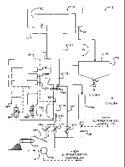
[0022] Figure 1 shows a fluidized bed reactor system 12. System 12
has an inlet 13 which receives wastewater from, for example, a
municipal, industrial or agricultural wastewater treatment facility. The
S wastewater contains phosphorus and/or nitrogen which it is desired to
remove. The following example describes an application of the invention
to remove phosphorus from wastewater.
[0023] Where it is desired to target phosphorus for removal, the
I 0 concentrations of species within column 14 can be maintained at levels
such that it is the concentration of phosphorus that limits the reaction to
produce an end product such as struvite. Those skilled in the art will
realize that one could also target ammonia for removal by adjusting the
concentration of species within column 14 so that the concentration of
I 5 ammonia limits formation of the end product.
[0024] In this example the phosphorus is in the form of phosphate
(P043-) and related species such as HP04Z- . The phosphate concentration
in the wastewater may be in the range of 50 mg/L to 200 mg/L, for
20 example.
[0025] System 12 comprises a substantially vertical column 14.
Column 14 has a number of vertically sequential sections. The illustrated
reactor has four sections 15A, 158, 15C and 15D (collectively sections
25 15). Section 15A may be termed a "harvesting section" because pellets
formed within column 14 can be extracted from section 15A after they
have grown to a suitable size, as described below. In the illustrated
CA 02552842 2006-07-07
WO 2005/077834 PCT/CA2004/000208
- 10-
embodiment, column 14 has a step discontinuity 17 at the boundary
between each pair of adjacent sections 15. The cross sectional area of
column 14 changes stepwise at each step discontinuity 17.
[0026] The term "step-like transition" is used herein to refer to
transitions between sections 15 wherein the angle 0 (see Figure 1 )
between the wall of a section below a step-like transition and the
transition is 80 degrees or greater. It is currently believed that providing
stepwise transitions, or at least step-like transitions, between sections 15
enhances the size-classification of particles within column 14,
particularly where the transitions are located near the top of column 14.
[0027 The dimensions of column 14 and the number of sections 15
may be varied depending upon the volume of wastewater to be treated as
discussed further below. In some small-scale prototype embodiments of
the invention, each of the segments is cylindrical. Table I provides
segment diameters as used in several prototype embodiments of the
invention.
TABLE I - SEGMENT
DIAMETERS IN
SOME PROTOTYPES
SEGMENT DIAMETER
(cm)
PROTOTYPE 15A 15B 15C 15D
1 4 5.2 7.7 20
2 4 5.2 7.7 20
3 7.7 10.2 15.2 40
4 7.7 10.2 15.2 40
CA 02552842 2006-07-07
WO 2005/077834 PCT/CA2004/000208
-11-
[0028] The ratio of the cross-sectional area of the uppermost
section 15 to that of the lowermost section 15 is typically 10:1 or more
and may be 20:1 or greater still. For example, in prototype 1 of Table l,
the ratio of the cross sectional area of section 15D to section 15A is
about 25:1. The ratio of cross-sectional areas of adjacent sections 15 is
typically in the range of 1.5:1 to 10:1 with the cross-section increasing
toward the top of column 14.
[0029] In some embodiments, the cross sectional area of adjacent
segments increases by a factor of at least 1'/Z. The cross sectional area
may increase by a larger factor between a next-to-topmost one of the
sections and a topmost one of the sections. For example, in some
embodiments, the topmost one of the sections has a cross sectional area
in excess of 5 times a cross sectional area of the next-to-topmost one of
the sections.
[0030) The lengths of the segments in the prototype reactors are
given in Table II.
TABLE II - SEGMENT
LENGTHS IN
SOME PROTOTYPES
SEGMENT LENGTH
(cm)
PROTOTYPE 15A 15B 15C 15D
1 101 108 250 46
2 106 275 93 46
3 76 155 127 46
CA 02552842 2006-07-07
WO 2005/077834 PCT/CA2004/000208
- 12-
4 I 93 I 127 I 128 I 46
Since the amount of energy required to circulate fluid through a column
increases with the height of the column, it is generally desirable to limit
the height of column 14 to 5 meters or so. Taller columns could be used
but would be disadvantaged by increased pumping costs unless the
wastewater is received under pressure.
[0031] An injection port 20 is provided at the bottom of column 14.
A fluid removal port 22 is provided at the upper end of column 14. A
recycling path 23 is provided to permit recycling of fluid from at or near
the top of column 14 to at or near the bottom of column 14. Further
details of the construction of reactor 14 are described below.
[0032] In operation, supersaturation conditions for struvite (or a
struvite analog, or another desired solid reaction product) are maintained
within column 14. The struvite solubility product Ksp is given by:
Ksp _LMg2+~eq ~lll4+,eq [h~43 ~eq
where the activities of the different species (i.e. [Mg2+]eq, [NH4+]eq, and
[PO43-]eq ) are measured respectively as soluble magnesium, ammonia
and orthophosphate at equilibrium. The supersaturation ratio (SSR) is
given by:
SSR=[Mg2+][NH4+][P043 ]~ Ksp .
[0033] Increases in the SSR drive crystallization. It is desirable to
maintain the SSR in the range of abut 2 to S in the vicinity of injection
port 20. In some currently preferred embodiments of the invention the
CA 02552842 2006-07-07
WO 2005/077834 PCT/CA2004/000208
-13-
SSR is maintained in the range of about 3 to 4. As the SSR within
column 14 is increased past a SSR of about 4 or 5, the crystals of product
which form upon the introduction of wastewater into column 14 tend to
decrease in size. If too many of the crystals which form initially are too
small then the efficiency with which large pellets of product are formed
within the reactor may be reduced.
[0034] Measuring the SSR directly can be complicated because
ammonia and phosphate have different forms depending upon the pH.
The activity coefficients for ammonia and phosphate are pH dependent
and are difficult to estimate. Therefore, where estimates of KSp are based
upon measured concentrations of ionic species, the estimates of Ksn can
be pH dependent. It is typically simpler to measure the conditional
solubility of the end product (e.g. struvite) under various operating
conditions directly and to control the operation of reactor 12 based upon
measured concentrations of one or more species.
[0035] It is typically the case that the composition of wastewater
from a given source will be relatively constant over time or only slowly
changing. Where this is the case it may be sufficient to control the pH of
the wastewater within column 14 to have a set value and to adjust the set
pH value or other parameters of the operation of column 14 periodically
to maintain the SSR within the desired range.
[0036] In the embodiment illustrated in Figure l, the SSR is
controlled by adjusting the pH of the liquid within column 14, adding
magnesium ions, or both. Figure 2 shows that the solubility of struvite
CA 02552842 2006-07-07
WO 2005/077834 PCT/CA2004/000208
- 14-
decreases sharply with increasing pH. Increasing the pH by adding a
base, such as NaOH can therefore be used to increase the SSR within
column 14. For wastewater from some typical sources, the SSR can be
increased to levels sufficient to achieve acceptable phosphate removal
by raising the pH by 0.5 to 1.5 units. Embodiments of the invention have
been operated satisfactorily with pH in section 15A of column 14 the
range of about 7.4 to 7.5. For phosphate removal rates exceeding 90% it
was found necessary to increase pH to 8.3.
[0037] For struvite crystallization it is generally desirable to add
magnesium ions to provide a stoichiometric mixture having a ratio of
Mg:N:P of approximately 1:1:1. Wastewater from many sources has less
magnesium than is desirable for the most efficient crystallization of
struvite. In general, for a fixed ratio of N:P, it has been found that
increasing the concentration of Mg tends to increase the amount of
phosphate that can be removed. It has been found that the average P-
removal ratio increases almost linearly with an increase in the molar ratio
of Mg:P in cases where the Mg:P ratio is below unity and the system is
therefore under-optimized for removal of phosphate.
[0038] The best way to control SSR depends upon the quality of
wastewater entering system 12. Depending upon factors such as the pH
of the entering wastewater, the amount of dissolved gases in the
wastewater, the temperature, the presence in the wastewater of species
which may inhibit crystallization, how close the wastewater is to
saturation, etc. it may be more cost effective to control SSR in column 14
by adjusting pH, adjusting the concentration of canons, or by some
CA 02552842 2006-07-07
WO 2005/077834 PCT/CA2004/000208
-15-
combination of adjusting pH and adjusting the concentration of cations
in column 14.
[0039] In the embodiment of Figure 1, SSR is controlled by a
supersaturation controller 30. Supersaturation controller may comprise
any suitable process controller. Suitable programmable process
controllers are widely available. For example, proportional feedback
controllers may be used to implement supersaturation controller 30.
Those skilled in the field of this invention are familiar with the selection
and programming of such controllers.
[0040] Supersaturation controller 30 receives as an input a signal
from a pH probe 32. pH probe 32 is located in column 14 just upstream
from an initial mixing zone 33. Above mixing zone 33, the influent
wastewater (including any recycled wastewater) and any chemicals
added to control the pH within column 14 are substantially fully mixed.
[0041 ] Supersaturation controller 30 controls the addition into
column 14 of a base, such as sodium hydroxide (NaOH), a source of
canons, such as magnesium, which may be provided in the form of a
magnesium chloride solution, or both. In the illustrated embodiment,
supersaturation controller 30 controls a metering mechanism 34 which
meters a sodium hydroxide solution from tank 35 into column 14 and a
metering mechanism 36 which meters a magnesium chloride solution
from tank 37 into column 14. Any suitable metering mechanisms may be
used to control the introduction of the chemicals used to control SSR into
column 14. Such metering mechanisms may include pumps, variable
CA 02552842 2006-07-07
WO 2005/077834 PCT/CA2004/000208
- 16-
valves, or the like. A wide range of suitable metering mechanisms are
available commercially.
[0042] Supersaturation controller 30 also controls a flow control
mechanism 38 which determines how much fluid which has already
passed through column 14 is recycled in recycling path 23. Flow control
mechanism 38 typically includes a feed pump which may be a low shear
pump. The recycle ratio provides a measure of the proportion of flow
introduced at nozzle 20 that is recycled via path 23. The recycle ratio RR
is provided by:
RR = Q'~ ( t )
~t- inf
where Q, is the recycle flow and Q,_;"f is the total influent flow into
column 14.
[0043] In one embodiment of the invention, supersaturation
controller 30 comprises a pH controller component 30A which meters a
basic (i.e. alkaline) solution from tank 35 to maintain the pH at pH sensor
32 at a desired value. Supersaturation controller 30 also includes a SSR
controller component 30B which controls the proportion of recycled
wastewater entering column 14 through recycle loop 23 to fresh
wastewater entering column 14 from inlet 13 to adjust the SSR and, if
necessary adds magnesium ions from tank 37 to keep the SSR within a
desired range. In the illustrated embodiment, supersaturation controller
also includes a flow control component 30C which controls an overall
25 flow of fluid through column 14.
CA 02552842 2006-07-07
WO 2005/077834 PCT/CA2004/000208
- 17-
[0044] SSR controller component 30B may obtain real-time
feedback from one or more sensors that monitor temperature, ionic
concentrations, pH and other factors that affect the SSR. In some typical
applications the composition of wastewater entering reactor 12 is only
very slowly changing, temperature is only slowly changing and pH is
maintained within a desired range by pH controller component 30A. In
such applications SSR controller component 30B need only to be
adjusted periodically based upon measurements indicative of SSR. Such
periodic measurements and adjustments may be performed manually or
under automatic control.
[0045] Nozzle 20 injects wastewater into column 14 in a turbulent
flow. In operation, an upward flow of fluid is maintained within column
14. The velocity of the flowing fluid decreases as the fluid enters each
successive section 15. Crystals of struvite form as wastewater enters
column 14. The crystals are urged upward in the flowing fluid and form a
fluidized bed. The fluidized bed extends through several sections 15.
The crystals grow through a combination of crystal growth and
aggregation. As the crystals grow, they become heavier and tend to move
downward within column 14.
[0046] Since the average upward fluid velocity is different in each
of sections 15, particles of struvite tend to become classified by size in
different sections 15. Initially all of the particles are small. The particles
in column 14 grow through crystal growth processes and by
CA 02552842 2006-07-07
WO 2005/077834 PCT/CA2004/000208
- 18-
agglomeration. As the crystals grow, some of the crystals become large
enough to drop into lower sections within column 14.
[0047] Over time, the largest particles tend to accumulate in section
15A. The smallest particles tend to accumulate in section 15D.
Intermediate-sized particles tend to become located within intermediate
sections 15B and 15C. Column 14 may include more intermediate
sections to provide a finer-scaled classification of particles by size in the
fluidized bed within column 14.
[0048] Fluid flows upward through column 14 at a rate sufficient to
maintain desired average upward fluid velocities in the different sections.
The average upward fluid flow velocities in each section 15 can be
ascertained by dividing the flow rate by the cross sectional area of the
section.
[0049] The average fluid flow velocity in the lowermost section is
sufficient to maintain struvite pellets in suspension. This flow velocity is
typically in excess of 100 cm/min. In some embodiments of the invention
the average upward fluid flow rate is about 500 cm/minute in section
15A. In general, it is desirable to maintain a relatively high fluid velocity
in the section from which the struvite pellets are harvested. This velocity
is advantageously in excess of 400 cm/minute and, in some embodiments
can be significantly higher, for example, 800 to 1000 cm/minute.
[0050] The upward flow velocity in the uppermost section of
column 14 is preferably much lower than it is in the lowermost section.
CA 02552842 2006-07-07
WO 2005/077834 PCT/CA2004/000208
- 19-
For example, in some embodiments of the invention the upward flow
velocity in the uppermost section 15 averages 75 cm/minute or less,
preferably 55 cm/min or less. In one embodiment of the invention the
average upward flow velocity in section 15D is approximately 50
cm/minute.
[0051] The rate at which wastewater flows through column 14 can
be controlled by adjusting inlet feed pump 39 and recycle flow control
mechanism 38 to provide a desired combined flow. In the illustrated
embodiment, flow rate is controlled by a flow rate controller component
30C incorporated in supersaturation controller 30.
[0052] Recycle path 23 includes a clarifier 50 for removing
ultrafine particles from the effluent of reactor 12. An effluent outlet 52
allows effluent to be drawn off from reactor 12.
[0053] Reactor 12 optionally includes an air stripping column 54.
Air stripping column 54 removes dissolved carbon dioxide from the
recycled wastewater passing through it and consequently increases the
pH of the recycled wastewater. Increasing the pH by way of an air
stripper reduces the need to add a base, such as NaOH to keep the SSR
within a desired range. Air stripping column 54 may be located in recycle
path 23, as shown, or may be in a fluid path separate from recycling path
23. Where air stripper 54 is in a flow path separate from recycling path
23, the rate at which fluid from column 14 is cycled through the air
stripping column can be controlled, for example, by pH controller
component 30A. This provides additional control over the pH of the fluid
CA 02552842 2006-07-07
WO 2005/077834 PCT/CA2004/000208
-20-
within column 14 and can reduce or, in some cases eliminate, the need to
add alkaline solution from tank 35.
[0054] After reactor 12 has been running for sufficient time, first
section 15A will contain pellets of struvite which are large enough to be
harvested. In the prototype reactors operated by the inventor, the first
struvite pellets have been ready for harvesting in about 8 to 20 days.
[0055] An isolation valve 40 is located in a lower portion of
column 14 and isolates at least a major portion of section 15A from the
upper parts of column 14. Isolation valve 40 is preferably located at or
below the boundary between section 15A and section 15B. The pellets
which have accumulated within section 15A can be harvested by opening
isolation valve 40 and closing valves 42 and 44 to temporarily isolate
section 15A. When section 15A is isolated, fluid can continue to flow
into the upper part of column 14 by way of bypass conduit 41 which
extends from input 20 to a location in column 14 above isolation valve
40. The contents of section 15A, including the struvite pellets which
have accumulated in section 15A, can be harvested by opening valve 46.
[0056] After having been removed from column 14 the pellets can
be dried. Any suitable drying system may be used. In the illustrated
embodiment, the pellets fall onto screen 48 from where they are
deposited onto a drying conveyor 49. Fluid from section 15A falls
through screen 48. The fluid can be captured and reintroduced into
system 12 or otherwise disposed o~
CA 02552842 2006-07-07
WO 2005/077834 PCT/CA2004/000208
-21 -
[0057] The quality and size of struvite pellets grown in reactor 12
depends upon a wide range of factors including SSR, flow rate in column
14, and crystal age. Lower SSRs, greater crystal age, and greater upflow
velocities in column 14 all tend to yield harder, and in some cases larger,
struvite pellets.
[0058] The crystal retention time, CRT, for a group of pellets
accumulated within column 14 may be defined as the number of days that
have passed since that volume of pellets have been removed from the
reactor. For example, if the settled volume of all pellets in column 14 is
found to be 7.8 L and 1.3 L of pellets are harvested from section 15A of
the reactor every 2 days then the CRT for the accumulated pellets would
be 12 days. It has been found in some experiments that CRT of 8-12 days
has generated good sized pellets that have sufficient structural strength to
endure harvesting and drying. In some embodiments of the invention the
process is operated to provide a CRT of 4 days or more and, in some
cases, 1 week or more.
(0059] In a prototype reactor constructed according to an
embodiment of the invention, it was found that up to about 90% of the
phosphates in wastewater could be removed in the form of struvite
pellets. The struvite pellets had diameters in the range of about 0.5 mm to
about 10 mm. The effluent from the process was found to have phosphate
concentrations as low as S mg/L.
[0060] Figure 3 illustrates a method 100 according to an example
embodiment of the invention. Method 100 takes fresh wastewater 101
CA 02552842 2006-07-07
WO 2005/077834 PCT/CA2004/000208
-22-
and recycled wastewater 102 and passes the wastewater into column in
block 104. A control process 106 continuously controls pH in block
106A, concentration of magnesium ions in block 106B, recycle ratio in
block 106C and flow rate in block 106D.
[0061] Effluent from the column is clarified in block 108. Some of
the effluent is recycled as indicated by line 110 to provide recycled
wastewater102. The remaining effluent is taken off at block 112.
[0062] Periodically pellets of struvite are extracted from the column
in block 120. The pellets are dried at block 122 to provide dry pellets at
block 124. The dry pellets may be used in various applications, for
example, as a fertilizer.
I 5 [0063] Where a component (e.g. a reactor, controller, conduit,
pump, metering mechanism etc.) is referred to above, unless otherwise
indicated, reference to that component (including a reference to a
"means") should be interpreted as including as equivalents of that
component any component which performs the function of the described
component (i.e., that is functionally equivalent), including components
which are not structurally equivalent to the disclosed structure which
performs the function in the illustrated exemplary embodiments of the
invention.
[0064] As will be apparent to those skilled in the art in the light of
the foregoing disclosure, many alterations and modif canons are possible
CA 02552842 2006-07-07
WO 2005/077834 PCT/CA2004/000208
- 23 -
in the practice of this invention without departing from the spirit or scope
thereof. For example:
~ The capacity of reactor 12 can be increased by operating multiple
columns 14 in parallel to one another.
~ For wastewater having phosphate concentrations in excess of 200
mg/L it may be desirable to provide an initial pretreatment stage
which reduces the phosphate concentration upstream from reactor
12. For example, the pretreatment stage could reduce phosphate
concentration to a value of less than about 200 mg/L.
~ The reactor could include a facility for adding ammonia as a
further, or alternative, mechanism for controlling the SSR.
~ The sections of reactor 14 do not need to be round in cross section.
Other shapes are also possible, for example, the sections could be
polygonal.
~ The number of sections could be varied.
~ The reactor can be operated to maximize removal of ammonium by
creating conditions under which the ammonium ions limit the
production of struvite.
~ While it is currently considered preferable that the transitions
between sections 15 of column 14 be sharp stepwise transitions,
some or all of the transitions could be tapered. For example the
transitions between the lowermost few sections 15 in column 14
could be tapered. Where column 14 includes tapered transitions, it
is considered advantageous that the tapered transitions be step-like
transitions. However, in some cases the taper angle could be 45
degrees or more or 60 degrees or more.
CA 02552842 2006-07-07
WO 2005/077834 PCT/CA2004/000208
-24-
~ The components of supersaturation controller 30 are not required
to be commonly located or housed but could be distributed in any
suitable manner.
~ The cross-sectional area of any section 15 is not necessarily
constant along the section but could vary in a manner that does not
interfere significantly with particle size classification within
column 14.
Accordingly, the scope of the invention is to be construed in accordance
with the substance defined by the following claims.