Sélection de la langue

Search

Sommaire du brevet 2552923 

Énoncé de désistement de responsabilité concernant l'information provenant de tiers

Une partie des informations de ce site Web a été fournie par des sources externes. Le gouvernement du Canada n'assume aucune responsabilité concernant la précision, l'actualité ou la fiabilité des informations fournies par les sources externes. Les utilisateurs qui désirent employer cette information devraient consulter directement la source des informations. Le contenu fourni par les sources externes n'est pas assujetti aux exigences sur les langues officielles, la protection des renseignements personnels et l'accessibilité.

Disponibilité de l'Abrégé et des Revendications

L'apparition de différences dans le texte et l'image des Revendications et de l'Abrégé dépend du moment auquel le document est publié. Les textes des Revendications et de l'Abrégé sont affichés :

  • lorsque la demande peut être examinée par le public;
  • lorsque le brevet est émis (délivrance).
(12) Brevet: (11) CA 2552923
(54) Titre français: DISPOSITIF DE TRANSPORT DE PIECES A TRAVAILLER DANS DES SYSTEMES DE PRESSAGE
(54) Titre anglais: DEVICE FOR CONVEYING WORKPIECES THROUGH PRESSING SYSTEMS
Statut: Périmé et au-delà du délai pour l’annulation
Données bibliographiques
(51) Classification internationale des brevets (CIB):
  • B21D 43/10 (2006.01)
  • B21D 43/05 (2006.01)
(72) Inventeurs :
  • REICHENBACH, RAINER (Allemagne)
(73) Titulaires :
  • MUELLER WEINGARTEN AG
(71) Demandeurs :
  • MUELLER WEINGARTEN AG (Allemagne)
(74) Agent: SMART & BIGGAR LP
(74) Co-agent:
(45) Délivré: 2009-07-21
(86) Date de dépôt PCT: 2005-02-04
(87) Mise à la disponibilité du public: 2005-08-18
Requête d'examen: 2006-07-17
Licence disponible: S.O.
Cédé au domaine public: S.O.
(25) Langue des documents déposés: Anglais

Traité de coopération en matière de brevets (PCT): Oui
(86) Numéro de la demande PCT: PCT/DE2005/000188
(87) Numéro de publication internationale PCT: DE2005000188
(85) Entrée nationale: 2006-07-17

(30) Données de priorité de la demande:
Numéro de la demande Pays / territoire Date
10 2004 006 085.1 (Allemagne) 2004-02-07

Abrégés

Abrégé français

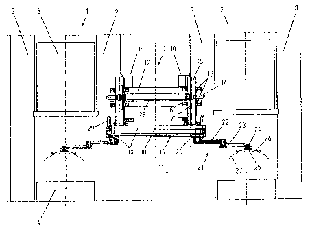
L'invention concerne un dispositif de transport de pièces dans des presses, notamment un alimentateur à bras à double articulation destiné à des presses à étages ou des trains de presses. Ce dispositif de transport doit être réalisé de manière à garantir une vitesse de transport élevée des pièces pour une grande rigidité du système. A cet effet, le bras articulé est monté basculant sur un chariot (20) qui porte le mécanisme de bascule et qui est guidé sur une traverse (18) sur laquelle au moins un mécanisme d'entraînement (29) fixe par rapport au chariot (20) assure le déplacement horizontal du chariot (20) et l'unité totale peut se déplacer verticalement par au moins un mécanisme de levage (14) fixe. Cette conception permet au bras articulé ou aux deux éléments bras articulés de n'avoir qu'une faible longueur saillante.


Abrégé anglais


The invention relates to a device for transporting work pieces through
pressing systems, in
particular a double hinged arm feeder for step presses or press working lines.
Said transport
device is configured in such a manner that the work pieces are transported at
high speed with a
large system rigidity. The hinged arm is pivotably mounted on a slit (20)
which supports the
pivot drive and which is guided on a rail (18) whereon at least one stationary
drive (29) is located
enabling the slits (20) to move in a horizontal manner in relation to the
slits (20) and the whole
unit can be moved in a vertical manner over at least one stationary lift drive
(14). Due to said
configuration, the hinged arm or the two hinged arm parts only have a small
looped length.

Revendications

Note : Les revendications sont présentées dans la langue officielle dans laquelle elles ont été soumises.


CLAIMS:
1. Conveying device for transporting workpieces
through processing stations of shaping machines, with a
conveying device that transports at least one workpiece in a
multi-axis transport movement, which is installed above the
plane of the workpiece transport between the processing
stations, the conveying device removing the workpiece from a
processing station and moving it through a lifting movement,
a horizontal pivoting movement about a vertical axis, and a
horizontal movement to the next processing station without
any intermediate positioning, the conveying device being
configured as at least one articulated arm with a first
articulated part and a second articulated part, wherein the
articulated arm is supported so as to be able to pivot on a
slide on which is installed a pivot drive and which is
guided on a traverse on which there is a drive, which is
fixed relative to the slide, for a horizontal movement of
the slide, and the complete unit is movable vertically
through at least one fixed lift drive.
2. Conveying device as defined in Claim 1, wherein
two articulated arms are disposed in a mirror image
arrangement relative to each other and driven in opposite
directions relative to each other by pivot drives and are
configured as a double articulated arm feeder.
3. Conveying device as defined in Claim 1, wherein a
crossbeam is pivotable about the axis by a drive, a gear
wheel, and a toothed quadrant.
4. Conveying device as defined in Claim 1, wherein
the crossbeam is pivotable about an axis by a drive.
7

5. Conveying device as defined in Claim 1, wherein
the workpiece retaining means is movable transversely to the
direction of movement of the workpiece by a drive.
8

Description

Note : Les descriptions sont présentées dans la langue officielle dans laquelle elles ont été soumises.


CA 02552923 2006-07-17
WO 2005/075123 PCT/DE2005/000188
Device for Conveying Workpieces through Pressing Systems
Description
The present invention relates to a device for conveying workpieces through the
processing stations of a press or press line.
Prior art
If production of a workpiece requires a plurality of processing stages such a
stamping and
shaping stages then, in the interests of economical production, the individual
operations
that are required are carried out in a sequential press, or a press working
line.
As a rule, such systems are provided with conveying devices that transport the
workpieces automatically. Various conveying devices of this kind are disclosed
in DE
195 21 976 Al. This document also discloses a so-called articulated arm
feeder. In a
particularly advantageous manner, the complete drive system is disposed above
the
workpiece transport plane. This structural form permits optimal accessibility
to the press
area.
The articulated arm feeder can be retrofitted to existing sequential presses
for large parts
or press working lines at no great cost. The articulated arm feeder can be
used for
mechanically and hydraulically powered presses without any restrictions.
In principle, the articulated arm feeder comprises two articulated parts that
form the
articulated arm. The articulated arm is powered in such a way that a pivoting
movement
in the horizontal plane can be made about a vertical axis. Additional degrees
of freedom
are provided for, such as horizontal mobility in and counter to the direction
in which the
workpieces are transported. A vertical lifting device is integrated into the
movable part
of the articulated arm feeder. The actual workpiece retaining means are
secured on
crossbeams, the so-called suction bars.
1

.., ..,
CA 02552923 2008-11-14
30683-4
Also known from this document is the fact that the
articulated arm feeder can be made with two articulated arms
that are disposed in a mirror image arrangement relative to
each other, i.e., as a so-called double articulated arm feeder.
Common to both versions is the fact that the freely
projecting articulated parts of the articulated arm are prone
to undesirable and powerful oscillations when subjected to
heavy dynamic loads.
Objective and advantages of the present invention
It is the objective of the present invention to avoid
the disadvantages discussed heretofore, and to so improve the
rigidity of the articulated arm feeder that more reliable
transport of the workpiece is ensured at a high dynamic level.
An aspect of the invention relates to conveying
device for transporting workpieces through processing stations
of shaping machines, with a conveying device that transports at
least one workpiece in a multi-axis transport movement, which
is installed above the plane of the workpiece transport between
the processing stations, the conveying device removing the
workpiece from a processing station and moving it through a
lifting movement, a horizontal pivoting movement about a
vertical axis, and a horizontal movement to the next processing
station without any intermediate positioning, the conveying
device being configured as at least one articulated arm with a
first articulated part and a second articulated part, wherein
the articulated arm is supported so as to be able to pivot on a
slide on which is installed a pivot drive and which is guided
on a traverse on which there is a drive, which is fixed
relative to the slide, for a horizontal movement of the slide,
and the complete unit is movable vertically through at least
one fixed lift drive.
2

,,
CA 02552923 2008-11-14
30683-4
The underlying concept of the present invention is that the articulated arm or
the two
parts of the articulated arm require only a small projecting length. In
addition, the mass
that is moved has been significantly reduced and the dynamics of the
articulated arm
improved thereby.
This has been achieved in that a slide that bears the articulated arm is moved
close up to
the press or forming station. To this end, the slide itself is provided with
only a
horizontal drive. The slide is guided and supported on a traverse that is, in
its turn,
connected to a vertical movement axis. This division of the movement axes
makes the
desired low-mass configuration possible. The great horizontal transport path
is thus
traveled by the slide and articulated arm that are acted upon by a small mass,
and this
permits high rates of acceleration and speed. The significantly smaller
vertical lift is then
completed together with the traverse.
2a

CA 02552923 2006-07-17
WO 2005/075123 PCT/DE2005/000188
Increased rigidity and reduced oscillation are additionally achieved by the
use of two
articulated arms as a double articulated arm feeder. The crossbeam that is
located at the
front end of the articulated arm with the workpiece retaining means is
supported
significantly better by the double articulated arm feeder.
In particular, the vertical and horizontal turning and tilting moments that
occur are
supported or in part balanced out. The acceleration forces that result from
the horizontal
acceleration when the workpiece is being transported are absorbed in a
favourable form
by the closed articulation layout.
An additional advantage of double articulated arm feeders is that the
installed height of
the articulated arms is reduced, with the result that, in addition to the
lower mass,
accessibility to the upper tool is improved when the workpiece is being put in
position or
removed.
The articulated arm feeder can be provided with additional degrees of freedom
without
any problem, so that it can perform all the movements that are needed in order
to change
the position of the workpiece with the result that-as a rule-neither
intermediate
positioning nor an orientation station is needed. Double parts can also be
transported
without any problems.
The connection of the articulated arm to the crossbeam with the workpiece
retaining
means is so configured that the most varied systems can be coupled by means of
adapters.
Energy is supplied to the workpiece retaining means by way of the two
articulated arms
in a low installed height with advantageous freedom of movement. At the point
of
rotation of the joint and on the crossbeam there are non-rotatable rollers for
the energy
guide chain, whereas the lever joints have rotatable rollers that are moved by
the energy
guide chain.
3

CA 02552923 2008-11-14
30683-4
Further details and advantages of the present invention are set out in the
description and
the drawings of an exemplary embodiment that follow. These drawings show the
following:
Figure 1: An illustration showing the principle of two presses of a press
working line
with a conveying device;
Figure 2: A plan view of Figure 1;
Figure 3: A. view of a press with a conveying device transversely to the
conveying
. device.
Description of the exemplary embodiment
Figure 1 shows two presses 1, 2 of a press working line. Also shown are the
ram 3, the
sliding table 4, and the stands 5 - 8. The conveying device 9 according to the
present
invention is held by two traverses 10 that are secured on the stands 6, 7
transversely to
the direction of movement 11 of the workpiece. A mounting plate. 12 is
connected to the
traverses 10 and supports the guide 13 and the lift drive 14 for the lift
columnl5. The
lifting movement is initiated by a gear wheel 16 that is secured on the shaft
of the lift
drive 14 and works in conjunction with a gear rack 17 that is disposed on the
lift column
15. The lift drive 14 can be twinned and both can be synchronized through a
connecting
tube 28. A traverse 18 is secured to the lower end of the lift column 15 with
the linear
guide 19 for the slide 20 of the articulated arm 21. The articulated arm
comprises a first
articulated part 22 and a second articulated part 23 that are both of the same
lever length.
At the outer end of the second articulated part 23 there is a receptacle for
the crossbeam
25 that supports the workpiece retaining means 26 for the workpiece 27.
The drives 29 are provided for horizontal transport movements and these
operate in
conjunction with a notched-belt drive 30 to which the slide 20 is secured. It
is plain to
see that with such a design arrangement the articulated arm 21 need only
project a short
distance. An optimal installed height and favourable accessibility to the
upper tool is
achieved thereby.
4

CA 02552923 2008-11-14
30683-4
Figure 2 shows the embodiment as a double articulated arm. The articulated
arms 21 are
installed in a mirror image arrangement relative to each other and are driven
in opposite
directions. The particular drive motor of the pivot drives 31 acts on the
first axis of pivot
32 through a transmission stage and on the second axis of pivot through a gear
chain.
The axis of pivot 33 is connected to the pivot and bearing shaft 34 through a
notched-belt
drive. The receptacle 24 for the crossbeam 25 is secured to the pivot and
bearing shaft
34. The drives 35 for rotation of the crossbeam 25 about its own axis 41, and
the drives
36 for the mobility of the workpiece retaining means 26 transversely to the
direction of
movement 11 of the workpiece 11 make other degrees of freedom possible. The
design
and movement sequence are described in detail in DE 195 21 976 A1.
Figure 3 shows pivoting transversely to the direction of movement 11 of the
workpiece as
an additional degree of freedom. A drive 37 drives a gear wheel 38 that
functions in
conjunction with a toothed quadrant 39 to pivot the workpiece 27 about the
axis 40. The
fixed lift drive 14 drives the gear wheel 16 thereby initiating the vertical
movement of the
lift column 15.
Structural details of the vertical mobility can also be seen in Figure 3. The
fixed lift drive
14 drives the gear wheel 16 thereby initiating the vertical movement of the
lift column
15.
The present invention is not restricted to the exemplary embodiment described
and
illustrated herein.

CA 02552923 2006-07-17
WO 2005/075123 PCT/DE2005/000188
1 Press 21 Articulated arm
2 Press 22 First articulated part
3 Ram 23 Second articulated part
4 Sliding table 24 Receptacle
Stand 25 Crossbeam
6 Stand 26 Workpiece retaining means
7 Stand 27 Workpiece
8 Stand 28 Connecting tube
9 Conveying device 29 Drive
Traverse 30 Notched belt drive
11 Workpiece conveying device 31 Pivot drive
12 Mounting plate 32 Axis of pivot
13 Guide 33 Axis of pivot
14 Lift drive 34 Pivot and support axis
Lift column 35 Drive
16 Gear wheel 36 Drive
17 Gear rack 37 Drive
18 Traverse 38 Gear wheel
19 Linear guide 39 Toothed quadrant
Slide 40 Axis
41 Axis
6

Dessin représentatif
Une figure unique qui représente un dessin illustrant l'invention.
États administratifs

2024-08-01 : Dans le cadre de la transition vers les Brevets de nouvelle génération (BNG), la base de données sur les brevets canadiens (BDBC) contient désormais un Historique d'événement plus détaillé, qui reproduit le Journal des événements de notre nouvelle solution interne.

Veuillez noter que les événements débutant par « Inactive : » se réfèrent à des événements qui ne sont plus utilisés dans notre nouvelle solution interne.

Pour une meilleure compréhension de l'état de la demande ou brevet qui figure sur cette page, la rubrique Mise en garde , et les descriptions de Brevet , Historique d'événement , Taxes périodiques et Historique des paiements devraient être consultées.

Historique d'événement

Description Date
Le délai pour l'annulation est expiré 2012-02-06
Lettre envoyée 2011-02-04
Accordé par délivrance 2009-07-21
Inactive : Page couverture publiée 2009-07-20
Inactive : Taxe finale reçue 2009-05-04
Préoctroi 2009-05-04
Lettre envoyée 2009-04-01
Un avis d'acceptation est envoyé 2009-04-01
Inactive : Approuvée aux fins d'acceptation (AFA) 2009-03-16
Modification reçue - modification volontaire 2008-11-14
Inactive : Dem. de l'examinateur art.29 Règles 2008-05-14
Inactive : Dem. de l'examinateur par.30(2) Règles 2008-05-14
Exigences relatives à une correction du demandeur - jugée conforme 2007-04-04
Lettre envoyée 2007-03-08
Inactive : Transfert individuel 2006-12-22
Inactive : Correction au certificat de dépôt 2006-12-21
Demande de correction du demandeur reçue 2006-12-21
Inactive : Lettre de courtoisie - Preuve 2006-09-19
Inactive : Page couverture publiée 2006-09-15
Lettre envoyée 2006-09-12
Inactive : Acc. récept. de l'entrée phase nat. - RE 2006-09-12
Demande reçue - PCT 2006-08-18
Inactive : IPRP reçu 2006-07-18
Exigences pour l'entrée dans la phase nationale - jugée conforme 2006-07-17
Exigences pour une requête d'examen - jugée conforme 2006-07-17
Toutes les exigences pour l'examen - jugée conforme 2006-07-17
Demande publiée (accessible au public) 2005-08-18

Historique d'abandonnement

Il n'y a pas d'historique d'abandonnement

Taxes périodiques

Le dernier paiement a été reçu le 2008-10-14

Avis : Si le paiement en totalité n'a pas été reçu au plus tard à la date indiquée, une taxe supplémentaire peut être imposée, soit une des taxes suivantes :

  • taxe de rétablissement ;
  • taxe pour paiement en souffrance ; ou
  • taxe additionnelle pour le renversement d'une péremption réputée.

Les taxes sur les brevets sont ajustées au 1er janvier de chaque année. Les montants ci-dessus sont les montants actuels s'ils sont reçus au plus tard le 31 décembre de l'année en cours.
Veuillez vous référer à la page web des taxes sur les brevets de l'OPIC pour voir tous les montants actuels des taxes.

Historique des taxes

Type de taxes Anniversaire Échéance Date payée
Requête d'examen - générale 2006-07-17
Taxe nationale de base - générale 2006-07-17
TM (demande, 2e anniv.) - générale 02 2007-02-05 2006-11-09
Enregistrement d'un document 2006-12-22
TM (demande, 3e anniv.) - générale 03 2008-02-04 2007-10-17
TM (demande, 4e anniv.) - générale 04 2009-02-04 2008-10-14
Taxe finale - générale 2009-05-04
TM (brevet, 5e anniv.) - générale 2010-02-04 2009-10-28
Titulaires au dossier

Les titulaires actuels et antérieures au dossier sont affichés en ordre alphabétique.

Titulaires actuels au dossier
MUELLER WEINGARTEN AG
Titulaires antérieures au dossier
RAINER REICHENBACH
Les propriétaires antérieurs qui ne figurent pas dans la liste des « Propriétaires au dossier » apparaîtront dans d'autres documents au dossier.
Documents

Pour visionner les fichiers sélectionnés, entrer le code reCAPTCHA :


Pour visualiser une image, cliquer sur un lien dans la colonne description du document. Pour télécharger l'image (les images), cliquer l'une ou plusieurs cases à cocher dans la première colonne et ensuite cliquer sur le bouton "Télécharger sélection en format PDF (archive Zip)" ou le bouton "Télécharger sélection (en un fichier PDF fusionné)".

Liste des documents de brevet publiés et non publiés sur la BDBC .

Si vous avez des difficultés à accéder au contenu, veuillez communiquer avec le Centre de services à la clientèle au 1-866-997-1936, ou envoyer un courriel au Centre de service à la clientèle de l'OPIC.


Description du
Document 
Date
(aaaa-mm-jj) 
Nombre de pages   Taille de l'image (Ko) 
Description 2006-07-16 6 218
Dessins 2006-07-16 3 64
Revendications 2006-07-16 2 48
Abrégé 2006-07-16 1 18
Dessin représentatif 2006-09-13 1 13
Revendications 2008-11-13 2 48
Description 2008-11-13 7 244
Abrégé 2009-05-14 1 18
Dessin représentatif 2009-06-24 1 14
Accusé de réception de la requête d'examen 2006-09-11 1 176
Rappel de taxe de maintien due 2006-10-04 1 110
Avis d'entree dans la phase nationale 2006-09-11 1 201
Courtoisie - Certificat d'enregistrement (document(s) connexe(s)) 2007-03-07 1 105
Avis d'entree dans la phase nationale 2006-09-11 1 200
Courtoisie - Certificat d'enregistrement (document(s) connexe(s)) 2007-03-07 1 105
Avis du commissaire - Demande jugée acceptable 2009-03-31 1 163
Avis concernant la taxe de maintien 2011-03-17 1 170
PCT 2006-07-16 5 197
Correspondance 2006-09-11 1 27
Taxes 2006-11-08 1 34
Correspondance 2006-12-20 2 125
PCT 2006-07-17 5 155
Correspondance 2009-05-03 1 37