Note : Les descriptions sont présentées dans la langue officielle dans laquelle elles ont été soumises.
CA 02553216 2012-09-20
POSITION SENSOR
FIELD OF THE INVENTION
The invention generally relates to position sensors, and more particularly to
a
position sensor operable within a cylinder.
BACKGROUND
There are different types of sensors that sense the position of some physical
object
and provide information as to the location or movement of that object. One
such sensor
is shown and described in U.S. Patent No. 6,694,861, issued February 24, 2004
and entitled "PRECISION SENSOR FOR A HYDRAULIC CYLINDER" and
which, in turn, is a continuation-in-part of U.S. Patent No. 6,234,061, issued
on
May 22, 2001, entitled "PRECISION SENSOR FOR A HYDRAULIC
CYLINDER".
Some applications for these sensors call for a sensor that is as small as
possible
and, in particular, where the sensor is located within a hydraulic cylinder
and where the
piston movement is relatively long. The need for relatively long piston
movement
requires a relatively lengthy connection between the moving piston and the
related Eked
point of the cylinder. Where the connection is a cable winding about a
rotating spool,
increased cable length, and perforce windings, may increase the probability of
overlapping of the cable coils on the rotating spool.
CA 02553216 2012-09-20
,
SUMMARY OF THE INVENTION
Certain exemplary embodiments can provide a position sensor comprising: a
frame
having a bushing having threads formed therein; a spool rotatably mounted to
the frame,
the spool having a threaded extension having mating threads that are
threadedly engaged
with the threaded bushing; a cable windable about the spool and having a
distal end
adapted to be affixed to an object to be sensed, wherein the spool rotates as
the cable winds
and unwinds in relation to the movement of the object, said spool operable to
travel along a
substantially linear path in response to the rotational movement of the spool;
and a sensing
means adapted to sense the position of the spool along its substantially
linear path.
Certain exemplary embodiments can provide a position sensor, comprising: a
frame; a spool rotatably affixed within the frame about a central axis of
rotation, a feed
point opening in said frame located in close proximity to the spool; a cable
passing
through the feed point opening and adapted to be wound around the spool to
form a
plurality of individual windings adjacent to but not overlapping each other
and having a
distal end adapted to be affixed to the object to be sensed, wherein the spool
rotates as the
cable winds and unwinds in relation to the movement of the object, said spool
operable to
travel along a substantially linear path along its axis of rotation as said
cable is wound or
unwound about said spool; a recoil spring that biases the rotational movement
of the spool
to cause the cable to wind up on the spool, the recoil spring having one end
affixed to the
rotatable spool and the other end fixed with respect to the frame; and a
sensing means
adapted to sense the position of the spool along its substantially linear
path.
Certain exemplary embodiments can provide a method of operating a sensor
comprising a frame having a bushing having threads formed therein, a rotatable
spool
having a threaded extension having mating threads that are threadedly engaged
with the
threaded bushing, and a cable windable about the spool and having a distal end
adapted to
be affixed to an object to be sensed, comprising the steps of: spool rotates
as the cable
winds and unwinds in relation to the movement of the object, said spool
operable to travel
2
CA 02553216 2012-09-20
along a substantially linear path in response to the rotational movement of
the spool;
rotating the spool to wind or unwind the cable in relation to the movement of
an object,
said spool operable to travel along a substantially linear path in response to
the rotational
movement of the spool; and sensing the position of the spool along its
substantially linear
path.
A sensor according to other embodiments provides a spool position sensor
having
an extended range of detection of an object, such as a piston within a
cylinder, within a
relatively small physical package. In one aspect of the invention, a spool is
provided that
moves so as to substantially align the feed point of the cable to the rotating
spool such that
the winding is aligned with the rest of the cable. As the spool rotates, it
continues to move
so that each successive winding does not overlap a previous winding, while
such
successive windings are made in substantial alignment with the cable length.
In another aspect, a sensor includes a rotatable spool around which the cable
is
coiled in a plurality of individual windings. A distal end of the cable is
affixed to the object
desired to be sensed. The winding and unwinding of the measuring cable causes
the spool
to rotate in accordance with the amount of cable extended or retracted from
spool. The
spool translates or travels along a linear path along the rotational axis of
the spool as the
cable winds and unwinds.
The position sensor can include a non-contacting sensor element, such as a
Hall-
effect sensor that then senses the linear travel. This sensor element can be
fixed to
the sensor frame and a magnetic target that is fixed to the linearly moving
spool or
an extension thereof so that an absolute position signal can be obtained in
direct
relation to the position of the object being sensed. The sensor can be
encapsulated in epoxy
to provide protection against pressure and immersion in fluid. Furthermore,
the hydraulic
2a
CA 02553216 2006-07-12
WO 2005/069857 PCT/US2005/001198
cylinder acts as a magnetic shield against spurious fields that could impart
measurand
error.
BRIEF DESCRIPTION OF THE DRAWINGS
In the drawings:
FIG. 1 is a side cross-sectional view of a position sensor constructed in
accordance with the present invention;
FIG. 2 is a side view of the position sensor of Fig. 1;
FIG. 3 is an exploded view of the recoil spool assembly and integral recoil
spring
of a sensor according to an exemplary embodiment of the present invention;
FIG. 4 is a side cross-sectional view of an embodiment of the present
invention;
FIG. 5 is a perspective view of a position sensor according to the present
invention;
FIGs. 6A, 6B and 6C show an isometric assembled view, a partial exploded view,
and a side view respectively of a sensor according to the principles of the
invention;
FIG. 7 shows an exploded view of another sensor according to the principles of
the invention; and
FIG. 8 shows another sensor according to the principles of the invention.
DETAILED DESCRIPTION
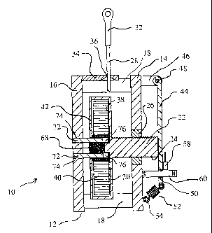
In Fig. 1, there is shown a perspective view of a position sensor 10
constructed in
accordance with the present invention. A use of the position sensor 10 is
shown and
described in the aforementioned U.S. Patent 6,234,061. As such, in Fig. 1
there can be
seen a stationary frame 12 that contains the components that make up the
position sensor
3
CA 02553216 2006-07-12
WO 2005/069857 PCT/US2005/001198
and the stationary frame 12 includes a front plate 14 and a rear plate 16 that
are held
together a predetermined distance apart by means of spacers 18. The frame is
stationary
in relation to the object to be sensed. Both the front and rear plates 14, 16
can be
constructed of steel or other relatively rigid material, including plastic
materials. While a
5
particular frame is described herein, the use of a frame is intended to
provide support for
the various components that make up the present invention, and the frame
itself can take
a variety of different shapes and configurations and may even be a portion of
the cylinder
when the present invention is used to detect the position of a piston moving
within a
cylinder.
10
Rotatably mounted within the stationary frame 12 is a spool 20. Spool 20 has a
threaded extension 22 extending outwardly therefrom along the rotational axis
of the
spool 20. As can be seen, the threaded extension 22 has male threads 24 and
there is a
threaded bushing 26 having corresponding female threads that is affixed to the
front plate
14 so that there is a threaded engagement between the threaded extension 22
and the
threaded bushing 26. As will be later explained, the particular pitch of the
mating threads
of the threaded extension 22 and the threaded bushing 26 are predetermined to
carry out
the preferred functioning of the position sensor 10.
A cable 28 is wound about the external peripheral surface of the spool 20 to
form
cable loops or windings 30, shown specifically in Fig. 2, that encircle the
spool 20. There
can be a cable attachment 32 located at the distal end of the cable 28 adapted
to be
affixed to the particular object whose position is desired to be sensed by use
of the
position sensor 10. As previously explained, in the embodiment of U.S. Patent
4
CA 02553216 2006-07-12
WO 2005/069857 PCT/US2005/001198
6,234,061, the object being sensed can be a piston to determine its position
within a
hydraulic cylinder. In any event, from the distal end of the cable 28 having
the cable
attachment 32, the cable 28 passes into the interior of the stationary frame
12 through a
lead guide 34 having a feed point opening 36 that is the feed point for the
cable 28 as it
winds and unwinds about the spool 20.
At this point, it can be recognized that the spool 20 rotates within the
interior of
the stationary frame 12 as the cable 28 is wound and unwound onto and from the
spool
20. As the spool 20 rotates, the threaded engagement between the threaded
extension 22
and the threaded bushing 26 causes the spool 20 to travel a linear path along
its axis of
rotation, that is, along the main axis of the threaded extension 22. Thus, the
linear travel
of the spool 20 is in a direct correlation to the linear movement of the cable
28 and, of
course, the linear movement of the particular object whose position is being
sensed.
The rather long linear distance traveled by the object is converted to a
rotary
movement of the spool 20 and then further converted to a relatively short-term
travel of
the threaded extension 22 such that by sensing and determining the travel and
position of
the threaded extension 22, it is possible to obtain an accurate determination
of the
location of the object that is being sensed. The conversion is basically
linear to rotary to
linear motion or LRL.
Returning to Figs. 1 and 2, in the embodiment shown, there is a hollowed out
area
38 within the spool 20 such that a recoil spring 40 is located within the
hollowed out area
38. The recoil spring 40 is essentially a spiral spring that biases the spool
20 in the
direction that it will rotate to wind the cable 28 onto the spool 20, that is,
the spool 20 is
5
CA 02553216 2006-07-12
WO 2005/069857 PCT/US2005/001198
biased so that it will tend to rotate in the winding direction. The function
of the recoil
spring 40 will be later described; it being sufficient at this point to note
that one end of
the recoil spring 40 is affixed to the spool 20 and the other end of the
recoil spring 40 is
held fixed with respect to the stationary frame 12.
The recoil spring 40 could also be located exterior to the spool 20, however,
as
can be seen there is an inherent space limitation within the stationary frame
12 and there
is a desire for such position sensors to be as small, dimensionally, as
possible for many
applications. As such, while the recoil spring 40 can be located in an
external position to
the spool 40, it takes up valuable space within the stationary frame 12 and
limits the
linear travel of the spool 20 as a simple result of having less space within
the stationary
frame 12. Accordingly, by locating the recoil spring 40 within the hollowed
out area 38
of the spool 20, there is an efficient use of the already limited space within
the stationary
frame 12. To enclose the recoil spring 40 within the hollowed out area 38,
there is also
provided a cover plate 42 that is affixed to the open end of the spool 20.
There is also provided in the embodiment of Fig. 1 and 2 a mechanism to
prevent
backlash at the threaded connection between the threaded extension 22 and the
threaded
bushing 26. That backlash mechanism comprises an arm 44 that is pivotally
mounted to
the stationary frame 12 by means of a standoff bracket 46 where there is a
pivot point 48
about which the arm 44 is pivotally affixed to the standoff bracket 46. At the
free end 50
of the arm 44, there is located a spring 52 having one end affixed to the free
end 50 of the
arm 44 and its other end affixed to the stationary frame 12 at a connector 54.
6
CA 02553216 2006-07-12
WO 2005/069857 PCT/US2005/001198
The spring basically biases the free end 50 of the arm 44 toward the
stationary
frame 12 at connector 54 so that there is a bias created that provides a force
at the contact
point 56 where the arm 44 contacts the end of the threaded extension 22 and
acts against
that threaded extension 22. Thus, there is a constant force exerted against
the threaded
extension 22 with respect to the stationary frame 12 and which prevents the
occurrence of
backlash at the threaded connection engagement between the threaded extension
22 and
the threaded bushing 26.
As previously explained, since the linear travel of the threaded extension 22
is a
direct result of the movement of the object to be sensed, by sensing the
movement or
travel of the threaded extension 22, and thus, its position, it is possible to
accurately
determine the position of the object being sensed. According, there can be a
wide variety
of means to determine the travel and location of the threaded extension 22, in
the
embodiment of Figs. 1 and 2, one of the sensing schemes can be through the use
of the
arm 44 which, as explained, moves directly with the threaded extension 22.
Accordingly, by sensing the movement of the arm 44, the linear travel of the
threaded extension can also be determined. As such, in Figs 1 and 2, there is
a sensor,
such as a Hall-effect sensor 58 that is affixed to the arm 44, generally
proximate to the
free end 50 and which operates in conjunction with a target magnet 60 which is
affixed in
a stationary position with respect to the stationary frame 12 and sufficiently
in close
proximity to the Hall-effect sensor 58 to allow the Hall-effect sensor 58 to
provide an
electrical signal indicative of the position of the arm 44 and, thus, the
position of the
threaded extension 22. Again, other sensors can be used and the actual
locations of the
7
CA 02553216 2006-07-12
WO 2005/069857 PCT/US2005/001198
Hall-effect sensor 58 and the target magnet 60 could be reversed, that is,
with the magnet
affixed to the arm 44 and the Hall-effect sensor 58 affixed in a stationary
position with
respect to the stationary frame 12.
Turning now to Fig. 3, taken along with Figs. 1 and 2, there is shown an
exploded
view of the recoil spring assembly according to the present invention. The
recoil spring
40 has an outer end 62 that is adapted to be affixed to the internal surface
of the spool 20
and an internal end 64 that forms a tab 66. In addition, there is a hub 68
having a slot 70
formed therein such that, in assembly, the tab 66 interfits within the slot 68
to retain the
inner end 64 of the recoil spring 40 to the hub 68. The hub 68 is, in tum,
affixed to the
stationary frame 12 such that the inner end 64 of the recoil spring 40 is in a
fixed position
with respect to the stationary frame 12 while the outer end 62 can move or
rotate along
with the rotation of the spool 20 so as to exert a bias on the spool 20
tending to rotate the
spool 20 in the direction of winding the cable 28 into cable loops 30 about
the spool 20.
Thus, the hub 68 is affixed to the stationary frame 12 to prevent hub 68 from
rotating while allowing the hub 68 to travel in a linear direction along with
the spool 20.
That affixation can be seen in Figs. 1 and 2 where there are a pair of guide
pins 72 that
are affixed to the rear plate 16 at 74 and which extend inwardly to slidingly
interfit into
corresponding bores 76 formed in the hub 68. As such, the guide pins 72
prevent the hub
68 from rotational movement while allowing the hub 68 to travel along a linear
path
along with the spool 20 as the spool 20 travels linearly due to its threaded
engagement
with the stationary frame 12.
8
CA 02553216 2006-07-12
WO 2005/069857 PCT/US2005/001198
Advantageously, the diameter of the winding surface of the spool and the pitch
of
the threads on the threaded extension may be selected such that relatively
long
displacement of the distal end of the sensing cable will produce a
corresponding, but
much smaller, linear travel of the spool and threaded extension. Additionally,
and in
conjunction with the above description, the thread pitch of the threaded
extension may be
selected to provide both the shorter measurable linear movement as well as a
single cable
width's movement per full 360 degree turn of the spool. In such way, the
present
invention provides for LRL measurement and extended range in a simple,
integrated
configuration.
Turning now to Fig. 4, there is shown a side cross sectional view of an
alternative
embodiment of the present invention where the sensing scheme, or means of
sensing the
travel and location of the threaded extension 22 comprises the target magnet
60 mounted
within the threaded extension 22 with the Hall-effect sensor 58 mounted in a
fixed
location on the front plate 14. Thus, in the embodiment of Fig. 4, the
movement or travel
of the threaded extension 22 is sensed directly rather than sensing the
movement of the
arm 44 in order to derive the movement of the threaded extension.
Turning now to Fig. 5, there is shown a perspective view of a further
embodiment
where there is a sensor, such as a Hall-effect sensor 58 that is affixed to
the front plate 14
and therefore held in a fixed position with respect to the stationary frame 12
and a target
magnet 60 that is affixed to a common shaft 78 with the arm 44 and therefore
pivots
along with the arm 44 about pivot point 48. Accordingly, with this embodiment,
the
sensor actually measures the angular position and movement of the arm 44 to
determine
9
CA 02553216 2006-07-12
WO 2005/069857 PCT/US2005/001198
the movement and position of the threaded extension 22 to thereby glean the
necessary
data to accurately determine the movement and position of an object being
sensed by the
position sensor 10.
FIGs. 6A, 6B and 6C show an isometric view, partially exploded view and side
view of another embodiment of a sensor 100 according to the principles of the
invention.
The principles of operation of this sensor 100 with respect to the rotating
spool 102 are as
previously described. In this sensor, however, magnet holding block 108 is
slidably
engaged with guide pins 109 and is adapted to hold a magnet via force fit in
the area 110.
The magnet 114 is moveable with the plate 106 in the hole 112 which permits
the magnet
114 to move linearly with the magnet holding block 108. The magnet can be a
Sintered
Alnico 8, available as Part No. 29770 from the Magnetics Products Group of SPS
Technologies, also known as Arnold Magnetics. The appropriate target magnet
for a
particular application can vary according to desired functionality and
engineering
considerations.
As can be seen in the side view of 6C, the magnet holding block 108 engages
the
rotating and translating spool 102 via a lead extension 116. The lead
extension 116
travels linearly with the action of the rotating spool 102 according to the
previously
described principles, although the precise mechanisms need not be employed. In
this
arrangement, therefore, the magnet 114 can travel without rotating with the
spool, and
can be located proximate a Hall effect sensor 118 which is here shown
partially hidden
and affixed to the plate 106 via a mounting block 120. In this embodiment, the
sensor
118 is an Allegro A3516L Ratiometric Hall-effect sensor. The engagement of the
CA 02553216 2006-07-12
WO 2005/069857 PCT/US2005/001198
holding block 108 with the lead extension 116 includes an offset adjusting
screw 122 and
is made via hole 124 in plate 106. The adjust screw 122 changes the
relationship of the
magnet 114 to the sensor 118 by moving the holding block 108 relative to the
extension
116. Anti-backlash springs 104a,b affix to the plate 106 and apply a
translational force to
the holding block 108, and, therefore to the lead 116 to prevent backlash due
to thread
dead space as previously described.
A compensating element 126 is also provided to compensate for measurand
inaccuracies arising from temperature impacts on the Hall sensor 118 and the
magnet. In
this embodiment, the element 126 is a thermally responsive metal adapted to
the Hall
effect in use. As the metal expands or contracts with temperature, the
sensor's 118
location respecting the magnet 114 changes to compensate for the sensor
changes caused
by temperature. Of course, other temperature compensation schemes can be
employed,
including electrical temperature compensation circuits adapted to the Hall
effect and
magnet combination in a particular implementation.
In one such electrical-based scheme, a reference Hall chip is used to sense
inaccuracies and subtract them from the measurement signal. The reference Hall
chip is
mounted in fixed relation to the target magnet, and is operable to sense
changes in
magnetic field due to temperature, age or the like. The reference chip should
be of the
same type as the primary, and therefore subject to the same temperature or
time induced
errors. The inaccuracies or errors, measured at a common source and using a
common
method cancel out using appropriate subtraction type circuit. Examples of such
circuits
can be of the balanced amplifier type. This circuit can include other
functionality, if
11
CA 02553216 2006-07-12
WO 2005/069857 PCT/US2005/001198
desired, such as voltage regulation, scaling, feedback, gain and offset
adjustments (either
on-board or externally adjustable via connector) and protection against
improper hookup.
An exploded view of another embodiment of a sensor 140 according to the
principles of the invention is shown in FIG. 7. The principles of operation of
this
embodiment are similar to that described in FIG. 6. As shown, however, the
anti-
backlash springs 142 apply force directly to the rotating spool 144, and the
threaded
extension 146 is fixed to the spool 144. An internally threaded insert 148 is
fixed to the
plate 150, such that when the spool 144 rotates, the threads of the extension
and insert
cooperate to move the spool laterally. Likewise, the carrier 152 also moves as
it is in
mechanical cooperation with the extension 146. Not shown in this embodiment is
the
particular transducer, although it should be appreciated that the
configuration is well
suited to a Hall effect sensor and magnet combination, and that in such
combination an
adjust screw and compensation element can be provided. Moreover, this
embodiment is
suited to a swage type construction, providing a low cost sensor.
Exemplary signal conditioning board layout 802 and connector 804 particulars
are
shown in another embodiment 800 depicted in FIG. 8. Operation of the sensor is
as
previously described. In addition to IC layout, location of a reference Hall
effect sensor
806 is also shown.
Other, contacting sensing elements can also be used in the present invention
to
sense the position of the threaded extension and including, but not limited
to,
potentiometers. Where describing a sensing element and a target magnet, the
two
components can be reversed, that is, in the foregoing description of sensing
the position
12
CA 02553216 2006-07-12
WO 2005/069857 PCT/US2005/001198
of the threaded extension, the target magnet may be fixed to the stationary
frame or the
threaded extension and the sensing element fixed to the stationary frame or
the threaded
extension, respectively.
It is to be understood that the invention is not limited to the illustrated
and
described embodiments contained herein. It will be apparent to those skilled
in the art
that various changes may be made without departing from the scope of the
invention and
the invention is not considered limited to what is shown in the drawings and
described in
the specification. In particular, various features of the described
embodiments can be
added or substituted for features in other of the embodiments, depending upon
particular
requirements. All such combinations are considered to be described herein.
13