Sélection de la langue

Search

Sommaire du brevet 2553991 

Énoncé de désistement de responsabilité concernant l'information provenant de tiers

Une partie des informations de ce site Web a été fournie par des sources externes. Le gouvernement du Canada n'assume aucune responsabilité concernant la précision, l'actualité ou la fiabilité des informations fournies par les sources externes. Les utilisateurs qui désirent employer cette information devraient consulter directement la source des informations. Le contenu fourni par les sources externes n'est pas assujetti aux exigences sur les langues officielles, la protection des renseignements personnels et l'accessibilité.

Disponibilité de l'Abrégé et des Revendications

L'apparition de différences dans le texte et l'image des Revendications et de l'Abrégé dépend du moment auquel le document est publié. Les textes des Revendications et de l'Abrégé sont affichés :

  • lorsque la demande peut être examinée par le public;
  • lorsque le brevet est émis (délivrance).
(12) Demande de brevet: (11) CA 2553991
(54) Titre français: MONTAGE A ROULEMENT AJUSTABLE POUR AXE TOURNANT
(54) Titre anglais: ADJUSTABLE BEARING ASSEMBLY FOR ROTATING SPINDLE
Statut: Réputée abandonnée et au-delà du délai pour le rétablissement - en attente de la réponse à l’avis de communication rejetée
Données bibliographiques
(51) Classification internationale des brevets (CIB):
  • F16D 03/16 (2006.01)
(72) Inventeurs :
  • BROOKE, CLAY (Royaume-Uni)
(73) Titulaires :
  • DENTSPLY INTERNATIONAL INC.
(71) Demandeurs :
  • DENTSPLY INTERNATIONAL INC. (Etats-Unis d'Amérique)
(74) Agent: SMART & BIGGAR LP
(74) Co-agent:
(45) Délivré:
(86) Date de dépôt PCT: 2005-01-20
(87) Mise à la disponibilité du public: 2005-08-11
Licence disponible: S.O.
Cédé au domaine public: S.O.
(25) Langue des documents déposés: Anglais

Traité de coopération en matière de brevets (PCT): Oui
(86) Numéro de la demande PCT: PCT/US2005/002250
(87) Numéro de publication internationale PCT: US2005002250
(85) Entrée nationale: 2006-07-19

(30) Données de priorité de la demande:
Numéro de la demande Pays / territoire Date
60/538,023 (Etats-Unis d'Amérique) 2004-01-20

Abrégés

Abrégé français

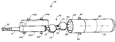
La présente invention concerne un montage à roulement ajustable (10) pour un axe tournant (11), présentant un raccord à billes (80) fixé sur une extrémité d'entraînement de l'axe, un roulement linéaire (102) fixé de manière ajustable sur l'axe (11), et un montage à roulement sphérique (70) fixé sur le raccord à billes (80) à une extrémité, et fixé à un moteur d'entraînement (20) à l'extrémité opposée. Le roulement linéaire (102) peut être utilisé pour ajuster et fixer la position de l'axe tournant (11) dans une direction essentiellement parallèle à l'axe linéaire de rotation (11a) de l'axe (11). Le moteur d'entraînement présente un axe de rotation (21) et une barre d'entraînement (50) excentrée par rapport à l'axe de rotation (21). La barre d'entraînement (50) présente une bille (60) de barre d'entraînement placée sur une extrémité opposée à la bille (80) et le montage à roulement sphérique présente une première sphère de réception de bille (71) conçue pour recevoir la bille (60). Une seconde sphère de réception de bille (72) est conçue pour recevoir le raccord à bille de l'axe tournant (11), et une bielle de connexion (73) est placée entre la première sphère et la seconde sphère (71, 72) de manière à les relier et dans une position espacée.


Abrégé anglais


An adjustable bearing assembly (10) for a rotating spindle (11) has a ball
connector (80) affixed to a drive end of the spindle, a linear bearing (102)
adjustably affixed to the spindle (11), and a spherical bearing assembly (70)
wherein the spherical bearing assembly (70) is affixed to the ball connector
(80) at one end and affixed to a drive motor (20) at an opposite end thereof.
The linear bearing (102) can be used to adjust and affix the position of the
spindle (11) in a direction substantially parallel to the linear axis of
rotation (11a) of the spindle (11). The drive motor has an axis of rotation
(21) and a drive bar (50) eccentrically offset from the axis of rotation (21).
The drive bar (50) has a drive bar ball (60) at an end opposite the ball (80)
and the spherical bearing assembly has a first ball receiving sphere (71)
configured to receive the drive bar ball (60). A second ball receiving sphere
(72) is adapted to receive the ball connector of the spindle (11), and a
connecting rod (73) is positioned between and connects the first and the
second ball receiving spheres (71, 72) in a spaced opposing relation.

Revendications

Note : Les revendications sont présentées dans la langue officielle dans laquelle elles ont été soumises.


What is claimed is:
1. An adjustable bearing assembly for a rotating spindle having a working end
and an oppositely positioned drive end, comprising a ball connector affixed to
the drive end of the spindle, a linear bearing adjustably affixed to the
spindle,
and a spherical bearing assembly wherein said spherical bearing assembly is
affixed to said ball connector at one end and affixed to a drive motor at an
opposite end thereof; wherein said linear bearing can be used to adjust and
affix the position of the spindle in a direction parallel to the linear axis
of the
spindle; said drive motor having an axis of rotation and a drive bar
eccentrically offset from said axis of rotation; said drive bar having a drive
bar
ball at an end opposite said drive motor; said spherical bearing assembly
having a first ball receiving sphere configured to receive said drive bar
ball,
and a second ball receiving sphere adapted to receive said ball connector of
the spindle, and a connecting rod positioned between and connecting said first
and said second ball receiving spheres in a spaced opposing relation.
2. An adjustable drive assembly for a rotating spindle comprising a drive
motor
and a flexible drive cable eccentrically mounted to said drive motor at one
and
to the spindle at its other end.
7

Description

Note : Les descriptions sont présentées dans la langue officielle dans laquelle elles ont été soumises.


CA 02553991 2006-07-19
WO 2005/073577 PCT/US2005/002250
ADJUSTABLE BEARING ASSEMBLY FOR ROTATING SPINDLE
TECHNICAL FIELD
[0001] The present invention is generally directed toward a rotating spindle.
More
particularly, the invention is directed toward a rotating spindle that is
rotated by an
adjustable bearing assembly that connects the spindle to a drive motor.
BACKGROUND OF THE INVENTION
[0002] Rotating spindles such as those used in dental handpieces, are often
attached
to a drive motor. There is often a connection between the drive motor and the
spindle,
and this extension is often a part of the drive motor axle. The length of that
connection is critical for the placement of the spindle itself. Great care is
required
when fabricating the arrangement so that the placement of the spindle is
precise as is
especially required with small components such as those of an electric motor,
dental
handpiece. Much time and effort is often expended in making and aligning the
various components. An example of an electric motor dental handpiece is shown
in
U.S. Pat. No. 6,425,761 which is hereby incorporated by reference for such
disclosure.
[0003] Further, during use the distances between the drive motors and the
rotating
spindles will vary, as will the position of the components in a direction
perpendicular
to their axes of rotation. Often the axis of rotation of the drive motor will
lie in a
different plane than that of the rotating spindle. Sometimes they will lie in
the same
plane and more often they will vary.

CA 02553991 2006-07-19
WO 2005/073577 PCT/US2005/002250
[0004] A need exists therefore for a bearing or combination of bearings that
makes
the connection between the drive motor and the spindle in a manner that is
adjustable.
In such a way, the alignment of the spindle can be made substantially
regardless of the
length or manufacturing tolerances of the component parts and substantially
regardless of the position of the drive motor relative to the rotating
spindle.
SUMMARY OF THE INVENTION
[0005] An adjustable bearing assembly for a rotating spindle according to the
invention has a working end and an oppositely positioned drive end. The
assembly
comprises a ball connector affixed to the drive end of the spindle, a linear
bearing
adjustably affixed to the spindle, and a spherical bearing assembly wherein
said
spherical bearing assembly is affixed to said ball connector at one end and
affixed to a
drive motor at an opposite end thereof. The linear bearing can be used to
adjust and
affix the position of the spindle in a direction substantially parallel to the
linear axis of
the spindle. The drive motor has an axis of rotation and a drive bar
eccentrically
offset from the axis of rotation. The drive bar has a drive bar ball at an end
opposite
the and the spherical bearing assembly has a first ball receiving sphere
configured to
receive the drive bar ball. A second ball receiving sphere is adapted to
receive the
ball connector of the spindle, and a connecting rod is positioned between and
connects
the first and the second ball receiving spheres in a spaced opposing relation.
BRIEF DESCRIPTION OF THE DRAWINGS
[0006] Figure 1 is a side plan view of an adjustable bearing assembly for a
rotating
spindle according to the present invention, shown for environmental purposes
in
conjunction with a drive motor.

CA 02553991 2006-07-19
WO 2005/073577 PCT/US2005/002250
[0007] Figure 2 is a perspective view of one portion of the assembly and drive
motor of Figure 1.
[0008] Figure 3 is an alternative embodiment of an adjustable bearing assembly
according to the invention.
[0009] Figure 4 is another alternative embodiment of an adjustable bearing
assembly according to the invention.
[0010] Figure S is another plan view of the invention as shown in Figure 1.
PREFERRED EMBODIMENT FOR CARRYING OUT THE INVENTION
[0011] A bearing assembly for a rotating spindle, according to the present
invention, is generally designated by the number 10 on the attached drawings.
While
the present invention has particular application in the field of dental
handpieces, such
as for use with dental burs, reamers and polishers (not shown), it also has
application
to any field wherein it is desired to connect a rotating spindle or other tool
to a drive
motor. For purposes of describing the present invention, reference may be made
to
the dental handpiece application for illustration only. As such, such a
conventional
rotating dental tool (not shown) can be affixed to a rotating spindle 11 by
any
conventional means such as by threads 12. It is also conventional to employ an
angled headpiece, such as is shown in U.S. Pat. No. 6,425,761, and as such,
spindle
11 may be operatively connected to such an angle piece.
[0012] A drive motor 20 is provided having a central axis 21 (shown in phantom
on
the drawings) of an axle 22 (Figure 5). Drive motor 20 may be of any
conventional
design such as being an air driven vane motor, but is preferably an electric
motor.
Drive motor 20 rotates axle 22 in a desired direction.
3

CA 02553991 2006-07-19
WO 2005/073577 PCT/US2005/002250
[0013] As best shown in Figure 5, there is affixed to axle 22 an armature 30
which
has a center axis 31 preferably coincident with center axis 21 of drive motor
20. By
being affixed to axle 22, armature 30 is caused to rotate about its axis 31 as
drive
motor rotates its axle 22 about its axis 21. As shown in Figure 1, armature 30
may be
housed in a race 40 having securing bolts 41 for affixing to a suitable
support such as
a dental handpiece housing (not shown). At an end generally opposite that of
its
connection to axle 22, armature 30 is provided with a protruding and offset
drive bar
50. By "offset" it is meant that as armature 30 rotates, offset drive bar 50
follows a
generally circular path around center axis 31 of armature 30. It is envisioned
that
non-circular paths are also be within the scope of the invention, but circular
paths will
be discussed here for simplicity. Offset drive bar SO may be cylindrical as
shown in
the drawings or may be any other shape. If cylindrical it would have a center
axis S 1
that is offset some distance D (Figure 5) from center axis 31 of armature 30.
[0014] Figure 3 shows an alternative embodiment of the present invention that
will
be more fully discussed hereinbelow. However, Figure 3 clearly shows a
connecting
ball 60 affixed to offset drive bar 50 that is useful with several embodiments
of the
invention as discussed herein. Positioned between spindle 11 and drive motor
20 is a
spherical bearing assembly generally designated by the number 70. Preferably,
spherical bearing assembly 70 has a first ball receiving sphere 71 and a
second ball
receiving sphere 72 which may be positioned in a spaced opposing relation by a
connecting portion 73. First ball receiving sphere 71 is preferably configured
to be
hollow or semi-hollow so as to be dimensioned to receive connecting ball 60.
First
ball receiving sphere 71 may be configured with a slit 74 to facilitate
placing ball 60
therein. Ball receiving sphere 71 and 72 may be fabricated from any suitable
organic
or inorganic material such as metal, rubber, plastic, carbon or the like. It
is preferred
4

CA 02553991 2006-07-19
WO 2005/073577 PCT/US2005/002250
that when ball 60 is received within first ball receiving sphere 71 that it is
physically
held therein, such as by a friction fit or by device, such that drive bar 50
is caused to
rotate in a circular path about axis 31 of armature 30, ball 60 and the
physically
contacted first ball receiving sphere 71 is are likewise caused to rotate
about the same
axis 31 in a circular manner or other manner as may be associated with offset
drive
bar 50. Similarly, spindle 11 is provided with a spindle ball 80 that can be
received in
second ball receiving sphere 72 of spherical bearing assembly 70 in a like
manner to
that of ball 60 and first ball receiving sphere 71.
[0015] Connector 73 has a center axis or generally center line 90 that in
normal use
is offset at some angle from axis 21 of motor 20. It will thus be appreciated
that as
ball 60 is caused to move in a circular path about axis 21 of motor 20,
spindle ball 80
will be caused to rotate about a center axis 11 a of spindle 11. Because
spindle ball 80
is affixed to spindle 11, spindle 11 is also caused to rotate about its axis l
la.
[0016] Spindle 11 is preferably supported by a spindle race 100. Spindle race
100
may be affixed to a suitable support such as a dental handpiece housing (not
shown)
by any suitable means such as bolts 101. Preferably, spindle 11 is adjustable
in a
direction parallel to the linear dimension of its axis of rotation 11 a. Any
method of
supporting and effecting such linear adjustment is within the scope of the
invention.
For example, a linear bearing 102 may be affixed to race 100 and received
within a
linear bearing race 103. By sliding linear bearing 102 within linear bearing
race 103,
the placement of spindle 11 can be adjusted without changing the physical
dimension
of spindle 11. To affix spindle 11 in the selected position, bolts 104 may be
provided
through holes 105 in linear bearing race 103 such that bolts 104 physically
contact
linear bearing 102. It will also be appreciated that when moving spindle 11 to
the
desired position parallel to the linear dimension of its axis of rotation 11
a, the angle

CA 02553991 2006-07-19
WO 2005/073577 PCT/US2005/002250
between axis 90 and axis 21 is also changed. Again, this adjustment can be
finely
made substantially without regard to the physical or length dimensions of the
other
components. Thus a bearing assembly 10 is provided to adjust the position of
the
spindle 11.
[0017] An alternative embodiment of the present invention is shown for
illustrative
purposes in Figure 4. Rather than having a spherical bearing assembly 70
between
motor 20 and spindle 11, there is a flexible drive cable 110. By being
flexible and
longer in length than required to bridge the span between armature 30 and
spindle 11,
there is enough slack in drive cable 110 make up for or allow for any increase
or
decrease in such distance based upon the physical size of the various
components.
Flexible drive cable 110 may be mounted by any means such as a conventional
ring
bearing 111 which is offset in armature 30 in a manner substantially similar
to that of
drive bar 50 as above described.
[0018] Figure 3 shows another alternative embodiment of the invention wherein
a
spherical bearing 120 includes a single ball receiving sphere 121 attached to
spindle
11 by a jointed connector 122. As with all of the embodiments of the
invention, the
physical span between motor 20 and spindle 11 is made and the position of the
motor
20 relative to spindle 11, both in a direction parallel to or perpendicular to
the spindle
11 axis of rotation l la is also compensated for. Because these dimensions
will vary
both during production and during use of the device, the variance is
compensated for.
[0019] The invention has been described herein and shown on the drawings
without
attempting to show all of the variations that are within its scope and which
can be
readily changed. The scope of the invention shall be determined only by any
attached
claims.

Dessin représentatif
Une figure unique qui représente un dessin illustrant l'invention.
États administratifs

2024-08-01 : Dans le cadre de la transition vers les Brevets de nouvelle génération (BNG), la base de données sur les brevets canadiens (BDBC) contient désormais un Historique d'événement plus détaillé, qui reproduit le Journal des événements de notre nouvelle solution interne.

Veuillez noter que les événements débutant par « Inactive : » se réfèrent à des événements qui ne sont plus utilisés dans notre nouvelle solution interne.

Pour une meilleure compréhension de l'état de la demande ou brevet qui figure sur cette page, la rubrique Mise en garde , et les descriptions de Brevet , Historique d'événement , Taxes périodiques et Historique des paiements devraient être consultées.

Historique d'événement

Description Date
Demande non rétablie avant l'échéance 2010-01-20
Le délai pour l'annulation est expiré 2010-01-20
Inactive : Supprimer l'abandon 2009-10-06
Inactive : Renversement de l'état mort 2009-10-06
Inactive : Supprimer l'abandon 2009-10-06
Inactive : Correspondance - PCT 2009-07-22
Inactive : Correspondance - PCT 2009-04-17
Réputée abandonnée - omission de répondre à un avis sur les taxes pour le maintien en état 2009-01-20
Inactive : Morte - Aucune rép. à lettre officielle 2009-01-15
Inactive : Déclaration des droits - PCT 2008-10-15
Requête en rétablissement reçue 2008-10-15
Inactive : Renseign. sur l'état - Complets dès date d'ent. journ. 2008-04-21
Inactive : Abandon. - Aucune rép. à lettre officielle 2008-01-15
Inactive : Lettre officielle 2007-10-15
Inactive : Page couverture publiée 2006-09-20
Inactive : Lettre de courtoisie - Preuve 2006-09-19
Inactive : Notice - Entrée phase nat. - Pas de RE 2006-09-15
Demande reçue - PCT 2006-08-29
Exigences pour l'entrée dans la phase nationale - jugée conforme 2006-07-19
Demande publiée (accessible au public) 2005-08-11

Historique d'abandonnement

Date d'abandonnement Raison Date de rétablissement
2009-01-20
2009-01-20
2008-10-15

Taxes périodiques

Le dernier paiement a été reçu le 2008-01-02

Avis : Si le paiement en totalité n'a pas été reçu au plus tard à la date indiquée, une taxe supplémentaire peut être imposée, soit une des taxes suivantes :

  • taxe de rétablissement ;
  • taxe pour paiement en souffrance ; ou
  • taxe additionnelle pour le renversement d'une péremption réputée.

Les taxes sur les brevets sont ajustées au 1er janvier de chaque année. Les montants ci-dessus sont les montants actuels s'ils sont reçus au plus tard le 31 décembre de l'année en cours.
Veuillez vous référer à la page web des taxes sur les brevets de l'OPIC pour voir tous les montants actuels des taxes.

Historique des taxes

Type de taxes Anniversaire Échéance Date payée
Taxe nationale de base - générale 2006-07-19
TM (demande, 2e anniv.) - générale 02 2007-01-22 2007-01-03
TM (demande, 3e anniv.) - générale 03 2008-01-21 2008-01-02
Rétablissement 2008-10-15
Titulaires au dossier

Les titulaires actuels et antérieures au dossier sont affichés en ordre alphabétique.

Titulaires actuels au dossier
DENTSPLY INTERNATIONAL INC.
Titulaires antérieures au dossier
CLAY BROOKE
Les propriétaires antérieurs qui ne figurent pas dans la liste des « Propriétaires au dossier » apparaîtront dans d'autres documents au dossier.
Documents

Pour visionner les fichiers sélectionnés, entrer le code reCAPTCHA :


Pour visualiser une image, cliquer sur un lien dans la colonne description du document. Pour télécharger l'image (les images), cliquer l'une ou plusieurs cases à cocher dans la première colonne et ensuite cliquer sur le bouton "Télécharger sélection en format PDF (archive Zip)" ou le bouton "Télécharger sélection (en un fichier PDF fusionné)".

Liste des documents de brevet publiés et non publiés sur la BDBC .

Si vous avez des difficultés à accéder au contenu, veuillez communiquer avec le Centre de services à la clientèle au 1-866-997-1936, ou envoyer un courriel au Centre de service à la clientèle de l'OPIC.


Description du
Document 
Date
(aaaa-mm-jj) 
Nombre de pages   Taille de l'image (Ko) 
Description 2006-07-18 6 249
Dessins 2006-07-18 5 48
Revendications 2006-07-18 1 30
Abrégé 2006-07-18 1 68
Dessin représentatif 2006-09-19 1 6
Rappel de taxe de maintien due 2006-09-20 1 110
Avis d'entree dans la phase nationale 2006-09-14 1 192
Courtoisie - Lettre d'abandon (taxe de maintien en état) 2009-10-05 1 172
PCT 2006-07-18 1 23
Correspondance 2006-09-14 1 27
Correspondance 2007-10-14 2 34
Correspondance 2008-10-14 3 109
Correspondance 2009-04-16 1 42
Correspondance 2009-07-21 1 41