Note : Les descriptions sont présentées dans la langue officielle dans laquelle elles ont été soumises.
CA 02554316 2006-07-27
ELECTROACTIVE POLYMER-BASED PUMP
BACKGROUND OF THE INVENTION
[0001] Pumps play an important role in a variety of medical procedures. For
example, pumps
have been used to deliver fluids (saline, etc.) to treatment areas during
laparoscopic and
endoscopic procedures, to transport blood to and from dialysis and heart-lung
machines, and to
sample bodily fluids for analysis. Most medical pumps are centrifugal or
positive displacement
pumps positioned outside the surgical field and designed to withdraw or
deliver fluid.
[0002] Positive displacement pumps generally fall into two categories, single
rotor and multiple
rotors. The rotors can be vanes, buckets, rollers, slippers, pistons, gears,
and/or teeth which draw
or force fluids through a fluid chamber. Conventional rotors are driven by
electrical or
combustion motors that directly or indirectly drive the rotors. For example,
peristaltic pumps
generally include a flexible tube fitted inside a circular pump casing and a
rotating mechanism
with a number of rollers (rotors). As the rotating mechanism turns, the
rollers compress a
portion of the tube and force fluid through an inner passageway within the
tube. Peristaltic
pumps are typically used to pump clean or sterile fluids because the pumping
mechanism
(rotating mechanism and rollers) does not directly contact the fluid, thereby
reducing the chance
of cross contamination.
[0003] Other conventional positive displacement pumps, such as gear or lobe
pumps, use
rotating elements that force fluid through a fluid chamber. For example, lobe
pumps include two
or more rotors having a series of lobes positioned thereon. A motor rotates
the rotor, causing the
lobes to mesh together and drive fluid through the fluid chamber.
[0004] Centrifugal pumps include radial, mixed, and axial flow pumps.
Centrifugal pumps can
include a rotating impeller with radially positioned vanes. Fluid enters the
pump and is drawn
into a space between the vanes. The rotating action of the impeller then
forces the fluid outward
via centrifugal force generated by the rotating action of the impeller.
[0005] While effective, current pumps require large housings to encase the
mechanical pumping
mechanism, gears, and motors, thereby limiting their usefulness in some
medical procedures.
Accordingly, there is a need for improved methods and devices for delivering
fluids.
- 1 -
CA 02554316 2006-07-27
SUMMARY OF THE INVENTION
[0006] The present invention generally provides methods and devices for
pumping substances,
such as fluids, gases, and/or solids. In one exemplary embodiment, a pump
includes a first
member having a passageway formed therethrough and a plurality of actuators in
communication
with the first member. The actuators are adapted to change shape upon the
application of energy
thereto such that sequential activation of the plurality of actuators is
adapted to create pumping
action to move fluid through the first member.
[0007] The actuators can be formed from a variety of materials. In one
exemplary embodiment,
at least one of the actuators is in the form of an electroactive polymer
(EAP). For example, the
actuator can be in the form of a fiber bundle having a flexible conductive
outer shell with several
electroactive polymer fibers and an ionic fluid disposed therein.
Alternatively, the actuator can
be in the form of a laminate having at least one flexible conductive layer, an
electroactive
polymer layer, and an ionic gel layer. Multiple laminate layers can be used to
form a composite.
The actuator can also include a return electrode and a delivery electrode
coupled thereto, with the
delivery electrode being adapted to deliver energy to each actuator from an
external energy
source.
[0008] The actuators can also be arranged in a variety of configurations in
order to effect a
desired pumping action. In one embodiment, the actuators can be coupled to a
flexible tubular
member disposed within the passageway of the first member. For example, the
flexible tubular
member can include an inner lumen formed therethrough for receiving fluid, and
the actuators
can be disposed around the circumference of the flexible tubular member. The
pump can also
include an internal tubular member disposed within the inner lumen of the
flexible tubular
member such that fluid can flow between the inner tubular member and the
flexible tubular
member. The internal tubular member can define a passageway for receiving
tools and devices.
In another aspect, the actuators can be disposed within an inner lumen of the
flexible tubular
member and they can be adapted to be sequentially activated to radially expand
upon energy
delivery thereto, thereby radially expanding the flexible tubular member. As a
result, the
actuators can move fluid through a fluid pathway formed between the flexible
tubular member
and the first member.
- 2 -
CA 02554316 2013-07-17
[0009] In another embodiment, multiple actuators can be positioned radially
around a central hub
within the first member. A sheath can be positioned around the actuators, such
that axial
contraction of the actuators moves the sheath radially. Sequential movement of
the actuators can
draw fluid into one passageway and can expel fluid from an adjacent
passageway.
[0010] Further disclosed herein are methods for pumping fluid. In one
embodiment, the method
can include sequentially delivering energy to a series of electroactive
polymer actuators to pump
fluid through a passageway that is in communication with the actuators. In one
embodiment, the
series of electroactive polymer actuators can be disposed within a flexible
elongate shaft, and an
outer tubular housing can be disposed around the flexible elongate shaft such
that the
passageway is formed between the outer tubular housing and the flexible
elongate shaft. The
series of electroactive polymer actuators can expand radially when energy is
delivered thereto to
expand the flexible elongate shaft and pump fluid through the passageway. In
another
embodiment, the series of electroactive polymer actuators can be disposed
around a flexible
elongate shaft defining the passageway therethrough, and the series of
electroactive polymer
actuators can contract radially when energy is delivered thereto to contract
the flexible elongate
shaft and pump fluid through the passageway. In yet another embodiment, the
series of
electroactive polymer actuators can define the passageway therethrough, and
the series of
electroactive polymer actuators can radially contract when energy is delivered
thereto to pump
fluid through the fluid flow pathway.
[0010A] In one embodiment, there is provided pumping device, which includes: a
first member
having a passageway formed therethrough; a central hub disposed within the
first member; and a
plurality of actuators mated to the central hub and adapted to change shape
upon the application
of energy thereto such that sequential activation of the plurality of
actuators is adapted to create a
pumping action to move fluid through the first member.
[0010B] In another embodiment, there is provided a method of pumping fluid,
which includes:
sequentially delivering energy to a series of electroactive polymer actuators
mated to a central
hub to move the central hub and thereby pump fluid through a passageway in
communication
with the electroactive polymer actuators.
3
CA 02554316 2013-07-17
[0010C] In another embodiment, there is provided, a pumping device, which
includes: an
elongate member having first and second pathways formed therethrough; a
plurality of actuators
in communication with the elongate member and adapted to change shape upon the
application
of energy thereto such that sequential activation of the plurality of
actuators is adapted to create a
pumping action to move fluid through one of the first and second pathways.
[0011] BRIEF DESCRIPTION OF THE DRAWINGS
[0012] The invention will be more fully understood from the following detailed
description taken
in conjunction with the accompanying drawings, in which:
[0013] FIG. lA is a cross-sectional view of a prior art fiber bundle type EAP
actuator;
[0014] FIG. 1B is a radial cross-sectional view of the prior art actuator
shown in FIG. 1A;
[0015] FIG. 2A is a cross-sectional view of a prior art laminate type EAP
actuator having
multiple EAP composite layers;
3a
CA 02554316 2006-07-27
[0015] FIG. 2B is a perspective view of one of the composite layers of the
prior art actuator
shown in FIG. 2A;
[0016] FIG. 3A is a perspective view of one exemplary embodiment of a pump
having multiple
actuators disposed around a flexible tube;
[0017] FIG. 3B is a perspective view of the pump of FIG. 3A with the first
actuator activated;
[0018] FIG. 3C is a perspective view of the pump of FIG. 3A with the first and
second actuators
activated;
[0019] FIG. 3D is a perspective view of the pump of FIG. 3A with the first
actuator deactivated
and the second actuator activated;
[0020] FIG. 3E is a perspective view of the pump of FIG. 3A with the second
and third actuators
activated;
[0021] FIG. 3F is a perspective view of the pump of FIG. 3A with the second
actuator
deactivated and the third actuator activated;
[0022] FIG. 3G is a perspective view of the pump of FIG. 3A with the third and
fourth actuators
activated;
[0023] FIG. 4 is a cross-sectional view of another embodiment of a pump having
an actuator
positioned around the outside of an internal lumen;
[0024] FIG. 5 is a cross-sectional view of another embodiment of a pump
disclosed herein
including an internal passageway;
[0025] FIG. 6 is a cross-sectional view of yet another embodiment of a pump
disclosed herein
including an internal passageway;
[0026] FIG. 7 is a cross-sectional view of another embodiment of a pump
disclosed herein;
[0027] FIG. 8 is a cross-sectional view of still another embodiment of a pump
disclosed herein;
[0028] FIG. 9A is a cross-sectional view of the pump of FIG. 8;
- 4 -
CA 02554316 2006-07-27
[0029] FIG. 9B is a cross-sectional view of the pump of FIG. 8;
[0030] FIG. 10A is a cross-sectional view of another embodiment of a pump
disclosed herein;
[0031] FIG. 10B is a cross-sectional view of the pump of FIG. 10A;
[0032] FIG. 10C is a cross-sectional view of the pump of FIG. 10A; and
[0033] FIG. 10D is a perspective view of the pump of FIG. 10A.
DETAILED DESCRIPTION OF THE INVENTION
[0034] Certain exemplary embodiments will now be described to provide an
overall
understanding of the principles of the structure, function, manufacture, and
use of the devices
and methods disclosed herein. One or more examples of these embodiments are
illustrated in the
accompanying drawings. Those of ordinary skill in the art will understand that
the devices and
methods specifically described herein and illustrated in the accompanying
drawings are non-
limiting exemplary embodiments and that the scope of the present invention is
defined solely by
the claims. The features illustrated or described in connection with one
exemplary embodiment
may be combined with the features of other embodiments. Such modifications and
variations are
intended to be included within the scope of the present invention.
[0035] Disclosed herein are various methods and devices for pumping fluids. A
person skilled in
the art will appreciate that, while the methods and devices are described for
use in pumping
fluids, that they can be used to pump any substance, including gases and
solids. In general, the
method and devices utilize one or more actuators that are adapted to change
orientations when
energy is delivered thereto to pump fluid through a fluid pathway in
communication with the
actuators. While the actuators can have a variety of configurations, in an
exemplary embodiment
the actuators are electroactive polymers. Electroactive polymers (EAPs), also
referred to as
artificial muscles, are materials that exhibit piezoelectric, pyroelectric, or
electrostrictive
properties in response to electrical or mechanical fields. In particular, EAPs
are a set of
conductive doped polymers that change shape when an electrical voltage is
applied. The
conductive polymer can be paired with some form of ionic fluid or gel using
electrodes. Upon
application of a voltage potential to the electrodes, a flow of ions from the
fluid/gel into or out of
- 5 -
CA 02554316 2013-07-17
the conductive polymer can induce a shape change of the polymer. Typically, a
voltage potential
in the range of about 1V to 4kV can be applied depending on the particular
polymer and ionic
fluid or gel used. It is important to note that EAPs do not change volume when
energized, rather
they merely expand in one direction and contract in a transverse direction.
[0036] One of the main advantages of EAPs is the possibility to electrically
control and fine-tune
their behavior and properties. EAPs can be deformed repetitively by applying
external voltage
across the EAPS, and they can quickly recover their original configuration
upon reversing the
polarity of the applied voltage. Specific polymers can be selected to create
different kinds of
moving structures, including expanding, linear moving, and bending structures.
The EAPs can
also be paired to mechanical mechanisms, such as springs or flexible plates,
to change the effect
of the EAP on the mechanical mechanism when voltage is applied to the EAP. The
amount of
voltage delivered to the EAP can also correspond to the amount of movement or
change in
dimension that occurs, and thus energy delivery can be controlled to effect a
desired amount of
change.
[0037] There are two basic types of EAPs and multiple configurations for each
type. The first
type is a fiber bundle that can consist of numerous fibers bundled together to
work in
cooperation. The fibers typically have a size of about 30-50 microns. These
fibers may be
woven into the bundle much like textiles and they are often referred to as EAP
yarn. In use, the
mechanical configuration of the EAP determines the EAP actuator and its
capabilities for
motion. For example, the EAP may be formed into long strands and wrapped
around a single
central electrode. A flexible exterior outer sheath will form the other
electrode for the actuator
as well as contain the ionic fluid necessary for the function of the device.
When voltage is
applied thereto, the EAP will swell causing the strands to contract or
shorten. An example of a
commercially available fiber EAP material is manufactured by Santa Fe Science
and Technology
and sold as PANIONTM fiber and described in U.S. Pat. No. 6,667,825.
[0038] FIGS. 1A and 1B illustrate one exemplary embodiment of an EAP actuator
100 formed
from a fiber bundle. As shown, the actuator 100 generally includes a flexible
conductive outer
sheath 102 that is in the form of an elongate cylindrical member having
opposed insulative end
- 6 -
CA 02554316 2006-07-27
caps 102a, 102b formed thereon. The conductive outer sheath 102 can, however,
have a variety
of other shapes and sizes depending on the intended use. As is further shown,
the conductive
outer sheath 102 is coupled to a return electrode 108a, and an energy
delivering electrode 108b
extends through one of the insulative end caps, e.g., end cap 102a, through
the inner lumen of the
conductive outer sheath 102, and into the opposed insulative end cap, e.g.,
end cap 102b. The
energy delivering electrode 108b can be, for example, a platinum cathode wire.
The conductive
outer sheath 102 can also include an ionic fluid or gel 106 disposed therein
for transferring
energy from the energy delivering electrode 108b to the EAP fibers 104, which
are disposed
within the outer sheath 102. In particular, several EAP fibers 104 are
arranged in parallel and
extend between and into each end cap 102a, 120b. As noted above, the fibers
104 can be
arranged in various orientations to provide a desired outcome, e.g., radial
expansion or
contraction, or bending movement. In use, energy can be delivered to the
actuator 100 through
the active energy delivery electrode 108b and the conductive outer sheath 102
(anode). The
energy will cause the ions in the ionic fluid to enter into the EAP fibers
104, thereby causing the
fibers 104 to expand in one direction, e.g., radially such that an outer
diameter of each fiber 104
increases, and to contract in a transverse direction, e.g., axially such that
a length of the fibers
decreases. As a result, the end caps 102a, 120b will be pulled toward one
another, thereby
contracting and decreasing the length of the flexible outer sheath 102.
[0039] Another type of EAP is a laminate structure, which consists of one or
more layers of an
EAP, a layer of ionic gel or fluid disposed between each layer of EAP, and one
or more flexible
conductive plates attached to the structure, such as a positive plate
electrode and a negative plate
electrode. When a voltage is applied, the laminate structure expands in one
direction and
contracts in a transverse or perpendicular direction, thereby causing the
flexible plate(s) coupled
thereto to shorten or lengthen, or to bend or flex, depending on the
configuration of the EAP
relative to the flexible plate(s). An example of a commercially available
laminate EAP material
is manufactured by Artificial Muscle Inc, a division of SRI Laboratories.
Plate EAP material,
referred to as thin film EAP, is also available from EAMEX of Japan.
[0040] FIGS. 2A and 2B illustrate an exemplary configuration of an EAP
actuator 200 formed
from a laminate. Referring first to FIG. 2A, the actuator 200 can include
multiple layers, e.g.,
five layers 210, 210a, 210b, 210c, 210d are shown, of a laminate EAP composite
that are affixed
- 7 -
CA 02554316 2006-07-27
to one another by adhesive layers 103a, 103b, 103c, 103d disposed
therebetween. One of the
layers, i.e., layer 210, is shown in more detail in FIG. 2B, and as shown the
layer 210 includes a
first flexible conductive plate 212a, an EAP layer 214, an ionic gel layer
216, and a second
flexible conductive plate 212b, all of which are attached to one another to
form a laminate
composite. The composite can also include an energy delivering electrode 218a
and a return
electrode 218b coupled to the flexible conductive plates 212a, 212b, as
further shown in FIG.
2B. In use, energy can be delivered to the actuator 200 through the active
energy delivering
electrode 218a. The energy will cause the ions in the ionic gel layer 216 to
enter into the EAP
layer 214, thereby causing the layer 214 to expand in one direction and to
contract in a transverse
direction. As a result, the flexible plates 212a, 212b will be forced to flex
or bend, or to
otherwise change shape with the EAP layer 214.
[0041] As previously indicated, one or more EAP actuators can be incorporated
into a device for
pumping fluids. EAPs provide an advantage over pumps driven by traditional
motors, such as
electric motors, because they can be sized for placement in an implantable or
surgical device. In
addition, a series of EAPs can be distributed within a pump (e.g., along a
length of a pump or in
a radial configuration) instead of relying on a single motor and a complex
gear arrangement.
EAPs can also facilitate remote control of a pump, which is particularly
useful for implanted
medical devices. As discussed in detail below, EAPs can drive a variety of
different types of
pumps. Moreover, either type of EAP can be used. By way of non-limiting
example, the EAP
actuators can be in the form of fiber bundle actuators formed into ring or
donut shaped members,
or alternatively they can be in the form of laminate or composite EAP
actuators that are rolled to
form a cylindrical shaped member. A person skilled in the art will appreciate
that the pumps
disclosed herein can have a variety of configurations, and that they can be
adapted for use in a
variety of medical procedures. For example, the pumps disclosed herein can be
used to pump
fluid to and/or from an implanted device, such as a gastric band.
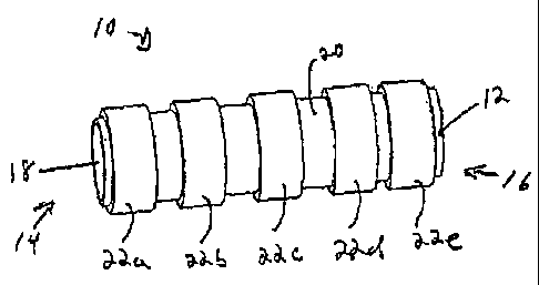
[0042] FIG. 3A illustrates one exemplary embodiment of a pumping mechanism
using EAP
actuators. As shown, the pump 10 generally includes an elongate member 12
having a proximal
end 14, a distal end 16, and an inner passageway or lumen 18 extending
therethrough between
the proximal and distal ends 14, 16. The inner lumen 18 defines a fluid
pathway. The pump 10
also includes multiple EAP actuators 22a, 22b, 22c, 22d, 22e that are disposed
around the outer
- 8 -
CA 02554316 2006-07-27
surface 20 of the elongate member 12. In use, as will be explained in more
detail below, the
actuators 22a-22e can be sequentially activated using electrical energy to
cause the actuators
22a-22e to radially contract, thereby contracting the elongate member 12 and
moving fluid
therethrough.
[0043] The elongate member 12 can have a variety of configurations, but in one
exemplary
embodiment it is in the form of a flexible elongate tube or cannula that is
configured to receive
fluid flow therethrough, and that is configured to flex in response to
orientational changes in the
actuators 22a-22e. The shape and size of the elongate member 12, as well as
the materials used
to form a flexible and/or elastic elongate member 12, can vary depending upon
the intended use.
In certain exemplary embodiments, the elongate member 12 can be formed from a
biocompatible
polymer, such as silicone or latex. Other suitable biocompatible elastomers
include, by way of
non-limiting example, synthetic polyisoprene, chloroprene, fluoroelastomer,
nitrile, and
fluorosilicone. A person skilled in the art will appreciate that the materials
can be selected to
obtain the desired mechanical properties. While not shown, the elongate member
12 can also
include other features to facilitate attachment thereof to a medical device, a
fluid source, etc.
[0044] The actuators 22a-22e can also have a variety of configurations. In the
illustrated
embodiment, the actuators 22a-22e are formed from an EAP laminate or composite
that is rolled
around an outer surface 20 of the elongate member 12. An adhesive or other
mating technique
can be used to attach the actuators 22a-22e to the elongate member 12. The
actuators 22a-22e
are preferably spaced a distance apart from one another to allow the actuators
22a-22e to radially
contract and axially expand when energy is delivered thereto, however they can
be positioned in
contact with one another. A person skilled in the art will appreciate that
actuators 22a-22e can
alternatively be disposed within the elongate member 12, or they can be
integrally formed with
the elongate member 12. The actuators 22a-22e can also be coupled to one
another to form an
elongate tubular member, thereby eliminating the need for the flexible member
12. A person
skilled in the art will also appreciate that, while five actuators 22a-22e are
shown, the pump 10
can include any number of actuators. The actuators 22a-22e can also have a
variety of
configurations, shapes, and sizes to alter the pumping action of the device.
[0045] The actuators 22a-22e can also be coupled to the flexible elongate
member 12 in a variety
- 9 -
CA 02554316 2006-07-27
of orientations to achieve a desired movement. In an exemplary embodiment, the
orientation of
the actuators 22a-22e is arranged such that the actuators 22a-22e will
radially contract and
axially expand upon the application of energy thereto. In particular, when
energy is delivered to
the actuators 22a-22e, the actuators 22a-22e can decrease in diameter, thereby
decreasing an
inner diameter of the elongate member 12. Such a configuration allows the
actuators 22a-22e to
be sequentially activated to pump fluid through the elongate member 12, as
will be discussed in
more detail below. A person skilled in the art will appreciate that various
techniques can be used
to deliver energy to the actuators 22a-22e. For example, each actuators 22a-
22e can be coupled
to a return electrode and a delivery electrode that is adapted to communicate
energy from a
power source to the actuator. The electrodes can extend through the inner
lumen 18 of the
elongate member 12, be embedded in the sidewalls of the elongate member 12, or
they can
extend along an external surface of the elongate member 12. The electrodes can
couple to a
battery source, or they can extend through an electrical cord that is adapted
to couple to an
electrical outlet. Where the pump 10 is adapted to be implanted within the
patient, the electrodes
can be coupled to a transformer that is adapted to be subcutaneously implanted
and that is
adapted to remotely receive energy from an external source located outside of
the patient's body.
Such a configuration allows the actuators 22a-22e on the pump 10 to be
activated remotely
without the need for surgery.
[0046] FIGS. 3B-3G illustrate one exemplary method for sequentially activating
the actuators
22a-22e to can create a peristaltic-type pumping action. The sequence can
begin by delivering
energy to a first actuator 22a such that the actuator squeezes a portion of
the elongate member 12
and reduces the diameter of the inner lumen 18. While maintaining energy
delivery to the first
actuator 22a, energy is delivered to a second actuator 22b adjacent to the
first actuator 22a. The
second actuator 22b radially contracts, i.e., decreases in diameter, to
further compress the
elongate member 12, as illustrated in FIG. 3C. As a result, fluid within the
inner lumen 18 will
be forced in the distal direction toward the distal end 16 of the elongate
member 12. As shown
in FIG. 3D, while maintaining energy delivery to the second actuator 22b,
energy delivery to the
first actuator 22a is terminated, thereby causing the first actuator 22a to
radially expand and
return to an original, deactivated configuration. Energy is then delivered to
a third actuator 22c
adjacent to the second actuator 22b to cause the third actuator 22c to
radially contract, as shown
in FIG. 3E, further pushing fluid through the inner lumen 18 in a distal
direction. Energy
- 10 -
CA 02554316 2006-07-27
delivery to the second actuator :22b is then terminated such that the second
actuator 22b radially
expands to return to its original, deactivated configuration, as shown in FIG.
3F. Energy can
then be delivered to a fourth actuator 22d, as shown in FIG. 3G, to radially
contract the fourth
actuator 22d and further pump fluid in the distal direction. This process of
sequentially
activating and de-activating adjacent actuators is continued. The result is a
"pulse" which travels
from the proximal end 14 of the pump 10 to the distal end 16 of the pump 10.
The process
illustrated in FIGS. 38-3G can be repeated, as necessary, to continue the
pumping action. For
example, energy can be again delivered to actuators 22a-22e to create a second
pulse. One
skilled in the art will appreciate that the second pulse can follow directly
behind the first pulse by
activating the first actuator 22a at the same time as the last actuator 22d,
or alternatively the
second pulse can follow the first pulse some time later.
[0047] In another embodiment, the pump 10 can include an outer elongate member
24 that
encloses the inner elongate member 12 and the actuators 22a-22e. This is
illustrated in FIG. 4,
which shows a cross-section of pump 10 having an outer elongate member 24
disposed around
an actuator 22, which is disposed around the flexible elongate member 12. The
outer elongate
member 24 can merely function as a housing to enclose the actuators and
optionally to provide
additional support, rigidity, and/or flexibility to the pump 10.
[0048] In another embodiment, the pump 10 can include additional elongate
members and/or
passageways. For example, as illustrated in FIG. 5, the pump 10 can include a
rigid or semi-
rigid internal member 26 that defines an axial passageway 28 through the pump
10. In use, the
passageway 28 can provide, for example, access to a surgical site for the
delivery of instruments,
fluid, or other materials, and/or for visual inspection. While the internal
member 26 is illustrated
as having a passageway, one skilled in the art will appreciate that it can
alternatively be a solid or
closed ended member that provides a surface that defines a fluid pathway
and/or that provides
structural support for pump 10.
[0049] While the actuators illustrated in FIGS. 3A-5 create pumping action by
radially
contracting to constrict the elongate member 12, pumping action can
alternatively be created by
radially expanding the actuator to increase a diameter of an elongate member.
For example, FIG.
6 illustrates a cross-sectional view of a pump 10' having an outer elongate
member 24' and a
- 11 -
CA 02554316 2006-07-27
flexible inner elongate member 12' that define a fluid flow passageway
therebetween. The
actuators (only one actuators 22' is shown) are positioned between an internal
member 26' and
the flexible inner elongate member 12'. The internal member 26' defines a
pathway for
providing access to a surgical site for the delivery of instruments, fluid, or
other materials, and/or
for visual inspection. In use, fluid can be pumped through the device 10' by
delivering energy to
the actuator 22' to radially expand the actuator 22', i.e., increase a
diameter of the actuator 22',
thereby radially expanding the flexible inner elongate member 12' toward the
outer elongate
member 24'. One skilled in the art will appreciate that the internal member
26' and/or the outer
member 24' of the pump 10' can be flexible, rigid, or semi-rigid depending on
the desired
configuration of pump 10'.
[0050] FIG. 7 illustrates another exemplary embodiment of a pump 10" that
utilizes fiber-bundle-
type actuators to create pumping action. In particular, the pump 10" can
include an elongate
member 26" defining a passageway 28" therethrough for providing access to a
surgical site for
the delivery of instruments, fluid, or other materials, and/or for visual
inspection. An inner
flexible sheath 30" and outer flexible sheath 32" are disposed around the
elongate member 26"
and they are spaced a distance apart from one another such that they are
adapted to seat the
actuators 22" therebetween. In other words, the outer-most flexible sheath 32"
can have a
diameter that is greater than a diameter of the inner flexible sheath 30". The
actuators 22" can be
formed into ring shaped members that are aligned axially along a length of the
pump 10". In use,
fluid can flow between the inner flexible sheath 30" and the elongate member
26". When energy
is delivered to an actuator 22", the actuator 22" contracts radially, i.e.,
decreases in diameter,
thereby moving the portion of the inner and outer flexible sheaths 30", 32"
that are positioned
adjacent to the activated actuator 22" toward the elongate member 26". As
previously explained,
energy can be sequentially delivered to the actuators 22" to create a pulse-
type pumping action.
[0051] As illustrated in FIG. 8, the pump 10" can also include an outer member
24" disposed
around the outer sheath 32". The space between the inner sheath 30" and the
elongate member
26" can define a first fluid pathway 36" and the space between the outer
sheath 32" and the outer
member 24" can define a second fluid pathway 38". Sequential activation of the
actuators 22"
can pump fluid through the first and second pathways 36", 38" simultaneously.
- 12 -
CA 02554316 2006-07-27
[0052] FIGS. 9A and 9b illustrate the pumping action of the actuators 22" in
pump 10" of FIG. 8.
In general, the actuators 22a-j" are sequentially activated to create a wave
action. This can be
achieved by fully activating some of the actuators, partially activating or
partially deactivating
adjacent actuators, and fully de-activating some of the actuators. As
previously explained, the
amount of energy delivered to each actuator can correlate to the amount of
radial expansion or
contraction that occurs. As shown in FIG. 9A, some of the actuators, e.g.,
actuators 22d" and
22i", are fully activated to constrict the inner sheath 30" such that a
portion of the inner sheath
30" adjacent to the 22d", 221" is positioned against the elongate member 26".
Adjacent actuators,
e.g., actuators 22b", 22c", 22e', 22g", 22h", 22j", are partially activated or
partially deactivated,
depending on the desired direction of movement of the fluid, and the remaining
actuators, e.g.,
actuators 22a" and 22f' are fully deactivated and in a fully expanded
configuration. As a result,
the actuators 22a-j" collectively form a wave configuration along the length
of the pump. As
energy delivery to each actuator 22a-j" continues to shift between fully
activated and fully
deactivated, the actuators 22a-j" will continue to expand and contract,
thereby moving fluid
through the pathways 36", 38". As shown in FIG. 9B, actuators 22d" and 22i"
are fully
deactivated such that they are radially expanded, adjacent actuators 22b",
22c", 22e', 22g", 22h",
22j" are partially activated or partially deactivated, and actuators 22a" and
22f' are fully activated
and in a fully contracted configuration. The actuators 22a-j" thus create
pressure in the fluid
pathways 36", 38" to squeeze the fluid therethrough.
[0053] In yet another embodiment, EAP actuators can be used in a lobe or vane
type pump.
FIGS. 10A-10D illustrate one embodiment of a pump 310 having an outer housing
340 that
defines a fluid passageway 341 therethrough, and that includes inlet and
outlet ports 350, 352. A
central hub 342 is disposed within the outer housing 340 and it includes
multiple actuators 322
extending therefrom in a radial configuration. An outer sheath 348 is disposed
around the
actuators 322 and the hub 342 to form an inner housing assembly. In use, the
actuators 322 can
be sequentially activated to move the inner housing assembly within the outer
housing 340,
thereby drawing fluid into pump 310 through the inlet port 350, move the fluid
through the pump
310, and expelling fluid through the outlet port 352.
[0054] The inner and outer housings can each have a variety of configuration,
but in an
exemplary embodiment each housing is substantially cylindrical or disc-shaped.
The outer
- 13 -
CA 02554316 2006-07-27
housing 340 is preferably formed from a substantially rigid material, while
the sheath 348 that
forms the inner housing is preferably formed from a semi-rigid or flexible
material. The
materials can, of course, vary depending on the particular configuration of
the pump 310.
[0055] The actuators 322 that are disposed within the sheath 348 are
preferably configured to
axially contract and expand, i.e., decrease and increase in length, to
essentially pull the sheath
348 toward the central hub 342, or push the sheath 348 away from the central
hub 342.
Sequential activation of the actuators 322 will therefore move the inner
housing in a generally
circular pattern within the outer housing 340, thereby pumping fluid through
the outer housing
340. A person skilled in the art will appreciate that the actuators 322 can be
configured to
axially expand, i.e., increase in length, when energy is delivered thereto,
rather than axially
contract.
[0056] Movement of the inner housing is illustrated in FIGS. 10A-10C. As shown
in FIG. 10A,
some of the actuators, e.g., actuators 322f, 322g, 322h, 322i, and 322j, are
partially or fully
activated (energy is delivered to the actuators) such that they are axially
contracted to pull the
portion of the sheath 348 coupled thereto toward the central hub 348. As a
result, a crescent
shaped area is formed within the outer housing 340 into which fluid 356 is
drawn. As shown in
FIG. 10B, the inner housing assembly is shifted by at least partially
deactivating some of the
previously activated actuators, e.g., actuators 322f, and 322g, and by at
least partially activating
adjacent actuators, e.g., actuators 322i, 322j, 322k, 3221, and 322a. This
sequential activation
further moves fluid 356 through the inner volume of outer housing 340.
Continued sequential
activation of actuators (e.g., 32:21, 322a, 322b, 322c, 322d, 322e, etc.) will
continue to move fluid
356 toward the outlet port 352, as shown in FIG. 10C. Once fluid 356 is
positioned near the
outlet port 352, activation of the actuators adjacent to the outlet port 352,
e.g., actuators 322a,
322b, 322c, will expel the fluid 356 through the outlet port 352.
[0057] One skilled in the art will appreciate further features and advantages
of the invention
based on the above-described embodiments. For example, the access port can be
provided in kits
having access ports with different lengths to match a depth of the cavity of
the working area of
the patient. The kit may contain any number of sizes or alternatively, a
facility, like a hospital,
may inventory a given number of sizes and shapes of the access port.
Accordingly, the invention
- 14 -
CA 02554316 2013-07-17
is not to be limited by what has been particularly shown and described, except
as indicated by the
appended claims.
- 15-