Note : Les descriptions sont présentées dans la langue officielle dans laquelle elles ont été soumises.
CA 02556618 2006-08-17
WO 2005/085107 PCT/US2005/006400
1
ROLL CHANGING APPARATUS
FIELD OF THE INVENTION
This invention relates to apparatus capable of providing a wound roll of
material to a
material-handling process. Specifically, the invention relates to apparatus
for exchanging a first
wound roll of material, particularly a depleted roll of material, or roll
remnant, for a second
wound roll of material. The invention relates particularly to the handling of
rolls of paper web
materials.
BACKGROUND OF THE INVENTION
Web materials are a ubiquitous part of daily life. Materials such as papers,
plastic films,
and metals may be processed by winding the material into a large roll having a
roll core and
subsequently unwinding the material from the large roll as a step in a process
to convert the
material into a finished product.
As the rolls of material are wound, a roll may be wound to a particular size
and then the
winding of the roll is stopped. The finished roll may be removed, an empty
core provided and the
winding of a subsequent roll begun.
During the unwinding of the material, a roll may be unwound until the useable
portion of
the roll is removed. The roll remnant may be removed, a subsequent roll
installed and then
unwound.
The exchange of a finished roll for a new roll core, or of a roll remnant for
a fresh roll,
may cause a stoppage of the web handling process. This stoppage may reduce the
overall
productivity of the process. Time spent by personnel and equipment making this
exchange, is time
taken away from other tasks. It is desirable to exchange the rolls as quickly
and efficiently as
possible. Quick and efficient exchanges may increase productivity by reducing
the duration of
process stoppages and also by reducing the time spent on the exchanges thereby
freeing
equipment and personnel for other tasks.
SUMMARY OF THE INVENTION
A roll-handling apparatus of the invention exchanges a roll remnant (remnant)
and a full
roll of material having a radius of about R. The roll-handling apparatus
comprises a dump cradle
capable of transitioning between a roll-support position and a roll-release
position. The roll-
handling apparatus further comprises a roll-transfer surface capable of
receiving the remnant from
the dump cradle. The roll-transfer surface comprises an extension element. The
extension element
CA 02556618 2006-08-17
WO 2005/085107 PCT/US2005/006400
2
is capable of transitioning from a retracted position to aii extended
position. The remnant may be
transferred from the dump cradle to the extended position. The extended
position may coincide
with a roll-removal position. The roll-handling apparatus further comprises a
roll-delivery
element capable of placing a fresh roll of material on the dump cradle and
subsequently removing
the remnant from the roll-removal position.
In another aspect the apparatus furtller comprises a trolley capable of
transitioning
between a roll-loading station and a roll-unwinding station. The trolley may
comprise the dump
cradle, and roll-transfer surface.
The apparatus of the invention may facilitate the delivery of a new roll and
the subsequent
removal of a remnant during a single trip of the roll delivery element.
BRIEF DESCRIPTION OF THE DRAWINGS
While the claims hereof particularly point out and distinctly claim the
subject matter of
the present invention, it is believed the invention will be better understood
in view of the
following detailed description of the invention taken in conjunction with the
accompanying
drawings in which corresponding features of the several views are identically
designated and in
which:
Fig. 1 is a schematic side view of one embodiment of the apparatus of the
invention.
Fig. 2A is a schematic perspective view of a roll handled according to one
embodiment of the
invention.
Fig. 2B is a schematic perspective view of a roll handled according to another
embodiment of the
invention.
Fig. 3 is a schematic plan view of a trolley according to one embodiment of
the invention.
Fig. 4 is a schematic sectional view of Fig. 3 taken along section line 4-4 of
Fig. 3.
Fig. 5A is a schematic plan view of a trolley and trolley stations according
to one enibodiment of
the invention.
Fig. 5B is a schematic plan view of two trolley and trolley stations according
to another
embodiment of the invention.
Fig. 5C is a schematic plan view of a multi-roll trolley and trolley stations
according to yet
another embodiment of the invention.
DETAILED DESCRIPTION OF THE INVENTION
The following description is applicable to the handling of rolls of web
material. The
nature of the web material is not a limitation of the apparatus. The apparatus
may be configured to
handle rolls of any web material. The apparatus may be configured to handle
paper, polymeric,
CA 02556618 2006-08-17
WO 2005/085107 PCT/US2005/006400
3
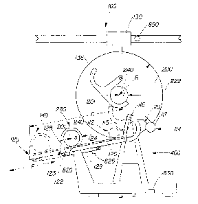
metal or other web materials. As illustrated in Fig. 1, the apparatus 100
comprises a dump cradle
110, a roll-transfer surface 120, and a roll-delivery element 130. The dump
cradle 110 is capable
of transitioning from a roll-support position 112 to a roll-release position
114. A roll remnant, or
remnant, 280, may be released by the dump cradle 110 and may be received by
the roll-transfer
surface 120. The roll-transfer surface 120 comprises an extension element 122.
The extension
element 122 is capable of transitioning from a retracted position 123 to an
extended position 125.
The remnant 280 may be transferred to the extended position 125. The extended
position 125 may
coincide with a roll-removal position 140. The roll-delivery element 130 may
provide a fresh roll
200 and may place the roll 200 on the dump cradle 110 when the dump cradle 110
is in the roll-
support position 112. The roll-delivery element 130 may subsequently remove
the remnant 280
from the roll-removal position 140.
The roll:
The ro11200 may comprise any generally cylindrical roll of web material W
wound about
a central axis 201. As illustrated in Figs. 2a and 2b the cylindrical roll 200
has a diameter and a
width. The roll 200 has a circumferential surface 222, and two sides 202. The
roll 200 may be
wound on a central shaft 240, or a hollow core 250, coincident with the
central axis 201 of the roll
200. Portions of the central shaft 240 or hollow core 250 may protrude beyond
the sides 202 of
the roll 200. The hollow core 250 may alternatively be generally flush with
the sides 202 of the
ro11200.
In one embodiment, rolls 200 having generally flush hollow cores 250 may have
core
inserts 260, inserted into the hollow cores 250. The core inserts 260 may
protrude from each of
the sides 202 of the rolls 200. The central shaft 240 and core inserts 260 may
provide surfaces for
the dump cradle 110 to support.
The size of the roll 200 is not a limitation of the apparatus of the
invention. The apparatus
100 may be scaled appropriately to handle rolls of any particular dimensions.
The apparatus:
The hereinafter described apparatus components may be comprised of metal,
wood, glass,
composite, or other materials appropriate to the intended use of the component
as are known in
the art.
The dump cradle:
The dump cradle 110 may comprise a single dump cradle 110 or a plurality of
dump
cradles 110. In the embodiments illustrated in Figs. 1, 3, and 4, the dump
cradle 110 comprises a
pair of dump cradles 110 disposed one at each end of the roll 200. Each dump
cradle 110 is
capable of supporting the roll 200 via a surface extending beyond a side 202
of the ro11200.
CA 02556618 2006-08-17
WO 2005/085107 PCT/US2005/006400
4
The dump cradle 110 may be configured to transition between the first roll-
support
position 112 and the second roll-release position 114 utilizing any means
known in the art. In one
embodiment, illustrated in Fig. 1, the dump cradle 110 may be configured to
use the force of
gravity to transition between the roll-support position 112 and the roll-
release position 114. In this
embodiment, the dump cradle 110 may be maintained in the roll-support position
112 by the
presence of a pawl 115 interfering with the movement of the dump cradle 110 to
the roll-release
position 114. In this embodiment, the mass of the remnant 280 may act upon a
pivot point 116 of
the dump cradle 110 to create a torque about the dump-cradle pivot point 116.
The torque may be
countered by the presence of the pawl 115 interfering with the rotation of the
dump cradle 110
about the pivot point 116. The dump cradle 110 may also be released from the
roll-support
position 112 by the use of a cog, a solenoid actuated release, or other means
know in the art.
The pawl 115 may be withdrawn at the discretion of an operator either manually
or
automatically, and either locally or remotely. The withdrawal of the pawl 115
enables the dump
cradle 110 to rotate in response to the torque created by the presence of the
remnant 280 in the
dump cradle 110.
The remnant 280 may be released by the dump cradle 110 at a point between the
roll-
support position 112 and the roll-release position 114, or the remnant 280 may
be released at the
roll-release position 114. When the remnant 280 is released from the dump
cradle, the torque
associated with the remnant 280 will be removed and the dump cradle 110 may
rotate back to the
roll-support position 112 by way of an oppositely directed torque arising from
the action of
gravity upon an appropriately sized and positioned counterweight 117. The pawl
115 may be
repositioned to interfere with the rotation of the dump cradle 110 between the
roll-support
position 112 and the roll-release position 114 as, or after, the dump cradle
110 returns to the roll-
support position 112. The size and position of the counterweight 117 may be
such that the torque
associated with the lightest possible remnant 280 is greater than the
counterweight torque, and is
sufficient to cause the rotation of the dump cradle 110 between the roll-
support position 112 and
the roll-release position 114. Other configurations of the counterweight are
possible such that the
motion of the dump cradle as it transitions between positions is in accordance
with the needs of
the roll-handling process.
In the embodiment illustrated in Fig. 4, the dump cradle 110 may be
transitioned by the
action of a dump-cradle end effector 118. A single dump-cradle end effector
118 may enable both
transitions, or an opposed pair of dump-cradle end effectors 118 may be used
to enable the
transitions. Exemplary end effectors include, without being limiting,
pneumatic or hydraulic
cylinders, linear servo motors, linear actuators, a rack and pinion system
coupled to a cylinder or a
rotary actuator, a belt drive system driven by an electric, hydraulic, or
pneumatically powered
CA 02556618 2006-08-17
WO 2005/085107 PCT/US2005/006400
motor, a system of chains and sprockets, and other means of generating motion
as are known in
the art.
In another embodiment (not shown), the dump cradle may be capable of
transitioning
from a first roll-receipt position to a second roll-support position to a
third roll-release position.
The dump cradle may be transitioned between these respective positions by the
above described
potential or kinetic energy actuators, and/or combinations thereof.
The roll-engaging element:
The apparatus may comprise at least one roll-engaging element. The roll-
engaging
element may be adapted to engage the hollow core 250, central shaft 240, or
core insert 260,
(collectively considered the engaged roll element) of the roll 200. As shown
in Figs. 3 and 4, the
engaging element 119 may comprise an actuator shaft 275 capable of engaging
the hollow core
250, or appropriate cavities in the ends of the central shaft 240 or the core
inserts 260. The
actuator shaft 275 may comprise splines or a tapered shaft matched with a
splined or tapered
cavity of the engaged roll element. The actuator shaft 275 may comprise an
expanding chuck
inserted into the engaged roll element and then circumferentially expanded
mechanically,
pneumatically, or hydraulically. The actuator shaft 275 may comprise partial,
or complete, threads
matched to threads in the engaged roll element. The engagement between the
actuator shaft and
the engaged roll element may be by other means as are known in the art.
The engagement of the engaging element 119 and the engaged roll element, may
lift the
roll 200 from the support of the dump cradle 110 such that the roll 200 is
supported by the
engaging element 119. The engaging element 119 may comprise one or more
bearing elements
270 capable of supporting the ro11200 as the ro11200 is rotated. These bearing
elements 270 may
be rotating-element bearings, solid-material bearings, journal bearings, or
other types of bearings
as are known in the art. The bearing elements may engage and support the roll
via the outside
surface of central shafts 240 or core inserts 260. The bearing elements 270
may engage and
support the actuator shafts 275 which in turn engage and support the roll 200.
The engaged roll
element may also comprise bearing surfaces (not shown) that engage and support
the actuator
shaft 275 as it engages the engaged roll element.
The engaging element 119 may comprise a roll end effector 300. The roll end
effector
may be coupled to the actuator shaft 275. The roll end effector 300 may be
electrically,
mechanically, hydraulically, or pneumatically rotated to rotate the roll 200.
The roll 200 may be
rotated to unwind the material W. Alternatively, the roll 200 may be rotated
to wind material W.
In another embodiment, the rol1200 may be rotated while held by the dump
cradle 110, or
the engaging elements 119, by a surface winding mechanism (not shown). The
surface winding
CA 02556618 2006-08-17
WO 2005/085107 PCT/US2005/006400
6
mechanism may contact the circumferential surface 222 of the roll 200 to
rotate the roll 200 and
unwind the web material W from the ro11200.
The engaging element 119 may be transitioned from a disengaged position 310 to
an
engaged position 320 and back to the disengaged position 3 10. The engaging
element 119 may
move along at least a portion of the winding axis to engage the roll 200. The
engaging element
119 may move linearly, by rotation, along a path defined by the motion of a
cam follower along a
cam, and any combination of these, into engagement with the ro11200. The
engaging element 119
may slide along a surface, may move in conjunction with a cylinder, or a rack
and pinion system
(not shown). The engaging element 119 may move in conjunction with a roll-
engaging-element
end effector (not shown). Exemplary end effectors include, without being
limiting, pneumatic or
hydraulic cylinders, linear servo motors, linear actuators, a rack and pinion
system coupled to a
cylinder or a rotary actuator, a belt drive system driven by an electric,
hydraulic, or pneumatically
powered motor, a system of chains and sprockets, and other means of generating
motion as are
known in the art.
In an en7bodiment where the engaging element 119 engages a core insert 260,
the
disengaging of the engaging element 119 from the core insert 260, may be
problematic. The
transition of the engaging element 119 from the engaged position 320 to the
disengaged position
310, may cause the core insert 260 to at least partially disengage from the
hollow core 250. In the
embodiment, illustrated in Fig. 4, the core insert 260 comprises an ejector
700 capable of exerting
a force in opposition to the withdrawal of the engaging elernent 119. The
exertion of this force
may maintain the engagement of the core insert 260 with the hollow core 250.
The ejector 700 may comprise a spring actuated system. As shown in Fig. 4, a
spring 710
is constrained between a base 720 and a cap 730. The cap 730 is configured to
contact the
engaging element 119 as the engaging element 119 is inserted into the cavity
268 of the core
insert 260. The motion of the engaging element 119 into the cavity 268,
compresses the spring
710. As the engaging element in withdrawn from the cavity 268, the expansion
of the spring 710
functions to disengage the engaging element 119 from the cavity 268 and to
forcibly maintain the
core insert 260 in engagement with the hollow core 250. In this embodiment,
the spring may be
any compression spring capable of decoupling the engaging element 119 from the
cavity 268. The
base 720 and the cap 730 may be cast or machined from any material capable of
enduring the
stresses of the ejection. Appropriately selected woods, polyrners, or metals
may be used for the
cap 730 and the base 720. Ultra-high-molecular-weight plastic is a non-
limiting example of a
material suitable for the cap 730 and the base 720.
In an alternative embodiment (not shown) the ejector 700 may comprise a
pneumatic
cylinder wherein the cylinder is compressed as the engaging element 119
engages the core insert
CA 02556618 2006-08-17
WO 2005/085107 PCT/US2005/006400
7
260, and the cylinder extends as the engaging element 119 is withdrawn. The
cylinder in this
einbodiment may be actively powered or may be a sealed cylinder relying upon
the expansion of
the previously coinpressed gas to extend the cylinder to eject the engaging
element 119.
Other means of generating a reactive force in opposition to the withdrawal of
engaging
element 119 as are known in the art may be used to maintain the engagement of
the core insert
260 with the hollow core 250.
The roll-transfer surface:
When the dump cradle 110 transitions to the roll-release position 114, the
remnant 280
may be released by the dump cradle 110 and received by the roll-transfer
surface 120. The roll-
transfer surface 120 defines a roll-transfer path P. The remnant 280 travels
along the roll-transfer
path P proceeding from the dump cradle 110 to a roll-removal position 140. The
roll-transfer
surface 120 may comprise a single surface or a plurality of surfaces across
the width of the
remnant 280, and along the length of the roll-transfer path P. The roll-
transfer surface 120 may be
configured to support the entire circumferential surface 222 of the remnant
280 or only a portion
of the surface. The roll-transfer surface 120 may be configured to support
only the portions of the
remnant 280 extending beyond the sides 202 of the web material W of the
remnant 280.
The roll-transfer surface 120 may proceed at a decline over at least a portion
of the roll-
transfer path P from the dump cradle 110, to enable the remnant 280 to move
along the roll-
transfer path P due to gravitational forces. The roll-transfer surface 120 may
comprise one or
more powered conveying surfaces (not shown) capable of transferring the
remnant 280 from the
dump cradle 110 to the roll-removal position 140. With this option, the roll-
transfer surface 120
may decline from the dump cradle 110, may incline from the dump cradle 110 may
be level with
the dump cradle 110.
The roll-transfer surface 120 may comprise one or more roll-contacting
surfaces 124
which contact at least a portion of the roll 200 or a surface protruding from
the sides 202 of the
roll 200. The roll-contacting surfaces 124 may be coinprised of any material
suitable for the
efficient transfer of the rolls 200 along the roll-transfer path P. Any, or
all, of the roll-contacting
surfaces 124 of the roll-transfer surface 120 may be surface hardened, coated
with a higli wear
coating, such as a plasma coating or a chromium coating, or prepared by other
means known in
the art for extending the service life of a wear surface. The roll-contacting
surfaces 124 may
comprise a sacrificial wear element (not shown) capable of easy replacement
and intended to
efficiently transfer the remnant 280. A low friction ultra-high-molecular-
weight polymeric
material, and a steel wear strip are non-limiting examples of sacrificial wear
elements.
The roll-transfer surface 120 may comprise an extension element 122 capable of
transitioning from a retracted position 123 to an extended position 125. The
terms extended and
CA 02556618 2006-08-17
WO 2005/085107 PCT/US2005/006400
8
retracted are not to be construed as limiting the motion of the extension
element 122 to a
reciprocal motion. The terms refer to an extension of the roll-transfer path
P. The roll-transfer
path P is lengthened as the extension element 122 transitions to the extended
position 125 and
shortened as the extension element 122 transitions to the retracted position
123.
The extension element 122 may comprise a single roll-contacting surface or a
plurality of
roll-contacting surfaces. The extension element 122 may be configured to
contact all or only a
portion of the remnant 280 or the surfaces protruding from the sides 202
thereof. The extension
element may comprise the above described roll-contacting surfaces 124.
In one embodiment (not shown), the extension element 122 may be transitioned
between
the retracted position 123 and the extended position 125 by way of gravity.
The design of the
extension element 122 may provide for the transition from the retracted
position 123 to the
extended position 125 by gravity acting upon the remnant 280 in conjunction
with the extension
element 122 to instigate the transition. The subsequent removal of the remnant
280 from the
extension element 122 would instigate the transition to the retracted position
123 by the action of
gravity upon an appropriate counterweight.
Returning to the embodiment, illustrated in Fig. 1, the extension element 122
may be
transitioned between the retracted position 123 and the extended position 125
by the use of one or
more end effectors 129. A single end effector 129 may enable both transitions,
or an opposed pair
of end effectors 129 may be used to enable the transitions. Exemplary end
effectors include,
without being limiting, pneumatic or hydraulic cylinders, linear servo motors,
linear actuators, a
rack and pinion system coupled to a cylinder or a rotary actuator, a belt
drive system driven by an
electric, hydraulic, or pneumatically powered motor, a system of chains and
sprockets, and other
means of generating motion as are known in the art.
The roll-transfer surface 120 may further comprise one or more roll stops 128.
Roll stops
128 are capable of limiting the motion of the reinnant 280 along the roll-
transfer surface 120. The
roll stops 128 may be positioned at the portion of the roll-transfer surface
120 furthest from the
dump cradle 110. The roll stops 128 may comprise a cushioned stop comprising a
shock-
absorbing cylinder, shoclc-absorbing foam, spring loaded stops, or other
impact absorbing
elements. The roll stops 128 may also comprise a fixed stop with little shock-
absorbing
capability, and/or other motion inhibiting means as are known in the art.
In one embodiment, the roll-transfer surface 120 may receive the remnant 280
from the
dump cradle 110 when the extension element 122 is in the retracted position
123. The remnant
280 may proceed along the roll-transfer surface 120 stopping at the roll stop
128. The roll-
transfer surface 120 may then extend as described, carrying the remnant 280
with it to the
extended position 125.
CA 02556618 2006-08-17
WO 2005/085107 PCT/US2005/006400
9
In an alternative embodiment, the roll-transfer surface 120 may extend prior
to the
transfer of the remnant 280 from the dump cradle 110 to the roll-transfer
surface 120. In this
embodiment, the renmant 280 may proceed along the roll-transfer path P from
the dump cradle
110 to the extended position 125 of the extension element 122. In another
embodiment, the
extension element 122 may transition from the retracted position 123 to the
extended position 125
as the renmant 280 is proceeding along the roll-transfer surface 120.
The position of the remnant 280 at the roll stop 128 when the extension
element 122 is in
the extended position 125 may coincide with the roll-removal position 140. In
the embodiment
illustrated in Fig. 1, the extended position 125 may allow the rernnant 280 to
move a distance
greater than the radius R of the subsequent roll 200 from the dump cradle 110.
The dump cradle
110 may be repositioned to the roll-support position 112 after the remnant 280
has been released
from the dump cradle 110. The disposition of the reinnant 280 at a roll-
removal position 140,
more than the radius R from the dump cradle, enables the roll-delivery element
130 to dispose a
subsequent roll 200 onto the dump cradle 110, prior to removing the remnant
280 from the roll-
removal position 140.
In an alternative embodiment (not shown) the renuiant 280 may proceed beyond
the
extended position 125 of the extension element 122 to a roll-removal position
140 further from
the dump cradle 110. In this embodiment, the extension element 122 provides a
retractable bridge
between portions of the roll-transfer surface 120 enabling the transit of the
remnant 280 from one
portion to the next and ultimately to the roll-removal position 140.
The distance D between the roll-removal position 140 and the dump cradle 110
will
determine the maximum diameter remnant 280 that may be transferred to the roll-
transfer surface
while still providing sufficient space in the apparatus 100 for the
disposition of a new roll 200 of
radius R on the dump cradle 110. The distance D - R will limit the size of the
remnant 280 that
can be transferred. The specific configuration of the apparatus will determine
how the distance D
- R relates to the maximum remnant 280 size. Fig. 1 illustrates as an example,
a roll-transfer
surface 120 configured with roll-contacting surfaces 124 that contact the
central shaft 240 and not
the material W of the remnant 280. For this configuration, the Distance D - R
will accommodate
a remnant 280 having a central shaft 240 radius of r and an overall radius of
S up to the limit
where r + S = D - R. It is possible to configure the apparatus such that the
distance D is greater
than the distance r + 2R. This configuration would permit a full roll 200 to
be released as a
renmant 280 and still provide sufficient space for the disposition of a
subsequent roll 200 prior to
the removal of the full roll remnant.
The above described configuration is not limited to the handling of rolls
wound on a
central shaft. Rolls 200 wound on a hollow core 250 may be accornmodated up to
the limit that
CA 02556618 2006-08-17
WO 2005/085107 PCT/US2005/006400
the radius r of the component in contact with the roll-transfer surface and
roll stop satisfies the
equation r=D-R-S.
The trolley:
As shown in Figs. 3 and 4, the dump cradle 110, engaging element 119, and roll-
transfer
surface 120 may comprise portions of a trolley 400. As shown in Fig. 5A, the
trolley 400 may be
capable of transitioning from a first roll-loading location 410 to a roll-
unwinding location 420. In
another embodiment shown in Fig. 5B, two trolleys may be disposed such that
the first trolley 400
transitions between a first roll-loading location 410 and the roll-unwinding
location 420, and a
second trolley 401 transitions between a second roll-loading location 411 and
the roll-unwinding
location 420. In this embodiment, the first trolley 400 receives a roll 200 at
the first roll-loading
location 410. The first trolley 400 transitions from the first roll-loading
location 410 to the roll-
unwinding location 420 and the roll 200 is unwound. The second trolley 401
receives a rol1200 of
material at the second roll-loading location 411. The first trolley 400 moves
from the roll-
unwinding location 420 to the first roll-loading location 410 to exchange the
remnant 280 of the
first roll 200 for a subsequent fresh roll 200 of material. The second trolley
401 moves from the
second roll-loading location 411 to the roll-unwinding location 420 and the
second roll 200 is
unwound. The trolleys 400, 401 alternate between their respective roll-loading
locations 410, 411
and the roll-unwinding location 420.
In another embodiment, shown in Fig. 5C, a single trolley 500 may comprise two
roll-
handling stations 505 and 515. In this embodiment, a first roll-handling
station 505 may be
present at the first roll-loading location 510 when the second roll-handling
station 515 is present
at the roll-unwinding station 520. When the trolley 500 transitions, the first
roll-handling station
505 may move to the roll-unwinding location 520, the second roll-handling
station 515 may move
to the second roll-loading location 511 and may exchange a remnant 280 for a
fresh roll 200.
After the roll 200 in the first roll-handling station 505 has completed
processing, the trolley 500
may transition such that the second roll-handling station 515 moves from the
second roll-loading
location 511 to the roll-unwinding location 520. Either one, or both, trolley
roll-handling stations
may comprise any of the above described remnant-handling elements and
combinations thereof.
The general operation of a roll-handling trolley with respect to the motion
enabling
devices for the trolley is well known in the art and will not be furtlier
discussed.
The roll-delivery element:
Returning to Fig. 1, the roll-delivery element 130 may operate at least partly
above the
dump cradle 110 and roll-transfer surface 120. The roll-delivery element 130
may be of any
design capable of effectively disposing a fresh roll 200 onto the dump cradle
110 and removing
the remnant 280 from the roll-removal position 140. The roll-delivery element
130 rnay comprise
CA 02556618 2006-08-17
WO 2005/085107 PCT/US2005/006400
11
a portion of an overhead gantry crane having an appropriate maximum weight
limit. The roll-
delivery element 130 may pick up a fresh ro11200 at a roll-storage location
(not shown). The roll-
delivery element 130 may convey the roll 200 vertically from the roll-storage
location aiid then
horizontally to the duinp cradle 110. The roll-delivery element may then
convey the roll 200
vertically into the dump cradle 110. The roll-delivery element 130 may
subsequently remove the
remnant 280 vertically from the roll-removal position 140. The general
operation of a roll-
delivery element 130, with respect to the motivational aspects of the element,
is well known in the
art and will not be further discussed.
The roll-delivery element 130 may be adapted to engage the engaged roll
element of the
roll 200. The roll-delivery element 130 may comprise a double hook 136. The
double hook 136
enables the roll-delivery element 130 to dispose a roll 200 on the dump cradle
110 and
subsequently pick up a remnant 280 from the roll-removal position 140 without
the necessity of
first passing the roll-removal position 140 and then returning to the roll-
removal position 140.
System Control:
In one embodiment, the apparatus 100 may be controlled manually by a human
operator.
In this embodiment, the operator may control the initiation of each step of
the operation of the
apparatus. The operator may further control the cessation of each step and the
successive initiation
of any subsequent step. The operator may control the apparatus through the use
of locally or
remotely situated controls.
In another embodiment, the performance of any of the steps described above
including
without limitation: providing a fresh roll 200 at the dump cradle 110,
removing the remnant 280
from the roll-removal position 140, transitioning extension element 122 of the
roll-transfer
surface 120 between an extended position 125 and a retracted position 123,
transitioning the
dump cradle 110 between a roll-support position 112 and a roll-release
position 1 14, and
transitioning a trolley 400 between a roll-loading location 410 and a roll-
unwinding location 420,
may be at least partially automated. Sensors may be provided to indicate the
position of the roll-
delivery element 130, the dump cradle 110, the extension element 122 of the
roll-transfer surface
120, the engaging element 119, the trolleys 400, 401, 500, and combinations
thereof. Additional
sensors may be provided to indicate the position of the end effectors
associated with the roll-
delivery element 130, the dump cradle 110, the extension element 122 of the
roll-transfer surface
120, the engaging element 119, the trolleys 400, 401, 500, and combinations
thereof.
These sensors may be configured to continuously provide the location of the
respective
sensed component. The sensors may also be configured to provide discrete
inputs when the
sensed components have reached predetermined locations. The input provided by
the sensor for a
given component may be reconciled with the input provided by the sensor for
the end effector
CA 02556618 2006-08-17
WO 2005/085107 PCT/US2005/006400
12
corresponding to that component and/or the desired location for the given
component provided
from a control program. This reconciliation may enhance the safe operation of
the machine. As an
example, the input from the sensor for the dump-cradle end effector 118 of the
dump cradle 110
may be referenced against the input value from the sensor for the dump cradle
110, and with the
desired value for the position of the dump cradle 110 from the control
program. In the event that
the input values and control program do not agree, within an appropriately
selected time window,
the progress of the roll-handling equipment may be halted until the source of
the disagreement
may be identified and corrected. A predetermined time window for the
reconciliation of the inputs
and desired value may be utilized to reduce the occurrence of false
indications of disagreement
resulting from differences in sensor response times.
The above described sensors may be configured to best suit the motion of the
particular
component. By way of example and without being limiting: the dump cradle 110
may have a
rotary motion between its respective positions and therefore a rotary encoder
may be used to
determine the position of the dump cradle 110. Linear position sensors may be
used to provide the
location of elements including the extension elements and the trolley. In one
embodiment, sensors
may be used to provide an indication of position associated only with each
extreme position of the
particular component. As a non-limiting example, a sensor may provide the
location of the
extension element 122 of the roll-transfer surface 120 only when the extension
element 122 is in
the retracted position 123 or in the extended position 125. In this
embodiment, sensors may
provide an input corresponding to the presence of the dump cradle 110 in each
of the roll-support
112 and roll-releasing positions 114 but nowhere else. Also in this
embodiment, the sensors may
provide inputs corresponding to the location of the trolley 400 when the
trolley 400 is disposed at
either the roll-loading location 410 or at the roll-unwinding location 420.
The sensors may
provide inputs to a controller configured to automatically sequence the steps
of providing a roll
200, removing a remnant 280, transitioning the trolley 400 and unwinding the
roll 200.
Fig. 1 illustrates the placement of sensors to indicate the position of
specific components.
According to the figure, the extension-element-end-effector position sensor
825 indicates the
position of the extension-element end effector 129. The extension-element
position sensor 820
indicates the position of the extension element 122. The roll-delivery-element
position sensor 850
indicates the position of the roll-delivery element 130. The trolley position
sensor 830 indicates
the position of the trolley 400.
Fig. 4 illustrates an exemplary placement of the dump-cradle position sensor
810, the
dump-cradle-end-effector sensor 815, and the engaging-element position sensor
840 to provide
indications of the dump cradle, the dump-cradle end effector, and the engaging
element 119
respectively.
CA 02556618 2006-08-17
WO 2005/085107 PCT/US2005/006400
13
Additional sensors (not shown) may be provided to indicate other operational
parameters
such as the presence of a roll at a particular location, or the diameter of a
roll during processing or
during handling. The use of such sensors is well known in the art and will not
be further discussed
herein.
The above described sensors may communicate with one or more process
controller (not
shown). This communication may be by any means known in the art for
communicating sensor
information to a controller. Non-limiting examples of the communication means
include
hardwiring the output of the sensor to an input circuits of the controller,
providing wireless link
between the sensor and the controller, providing a multiplexed signal link
between the sensor and
the controller.
One or more display panels (not shown) may be adapted to provide textual and
graphical
information regarding the operation of the apparatus. As a non-limiting
example, a graphic
representation of the apparatus may be provided. The graphic representation
may include real
time input data as to the location of each component of the apparatus and also
information relating
to an associated web processing process. Color variations and the use of
flashing graphic
elements, as are known in the art, may be employed to provide additional
information to a
machine operator. As a non-limiting example, a flashing green image may be
used to indicate that
a trolley is traiisitioning from a roll-loading location to a roll-unwinding
location. A red graphic
may indicate a component e.g. a trolley, which should be moving, or should be
at a location
specified by the control program, but is not in the desired state according to
the input value.
Light stacks (not shown) as are known in the art may be provided to enable a
determination of the operation of the apparatus from a distance, or from
locations where the
display panel cannot be viewed accurately, if at all. These light stacks may
use a combination of
light color and operation to convey status information. A continuously lit
green light may be used
to indicate normal safe operation. A flashing green light may indicate that
the apparatus is waiting
on the downstream process. A flashing red light may indicate that an apparatus
safety sensor has
been activated. In this manner a considerable amount of information may be
provided to a process
operator in an efficient manner.
Example 1:
An apparatus for handling parent rolls of paper web material, the parent rolls
having a
diameter of about 100 inches (254 cm). Core plugs having stub shafts are
inserted into each end of
the core of the roll at a roll-storage location. The roll is transported from
the roll-storage location
to a position above a roll-loading location of a trolley. The trolley moves
from a roll-unwinding
location to the roll-loading location when the operator desires to change the
remnant supported on
the trolley.
CA 02556618 2006-08-17
WO 2005/085107 PCT/US2005/006400
14
As the trolley moves, engaging elements retract from a position of engagement
with the
core plugs of the remnant. Ejectors in the core plugs assist the disengagement
of the engaging
element from the core plugs. As the engaging elements are withdrawn, the
remnant is lowered
onto a pair of dump cradles.
A first sensor detects the position of the engaging elements to ensure that
engaging
elements are clear of the remnant. A second sensor detects the diameter of the
remnant. Remnants
having a diameter of less than 36 inches (91.4 cm) may be transferred to the
roll-transfer surface.
Larger remnants are precluded from being transferred to the roll-transfer
surface due to the
diameter capacity of the particular apparatus.
For remnants having diameters less than 36 inches (91.4 cm) the operator
actuates the
dump-cradle end effector to transition the dump cradles. The dump cradles
change from the roll-
support position to the roll-release position. The remnant is transferred from
the dump cradles to
the roll-transfer surface. The dump cradles are transitioned back to the roll-
support position after
the release of the reinnant.
The remnant moves along the roll-transfer surface to the roll stop. After the
remnant has
reached the roll stop, an operator actuates an extension-element end effector
to extend the
extension element of the roll-transfer surface. The extension element and the
remnant move to the
roll-removal position.
The roll-delivery element disposes a new roll into the duinp cradles. The
engaging
elements move into engagement witli the roll lifting it from the support of
the dump cradles. The
roll-delivery element subsequently proceeds to the roll-removal position and
removes the
remnant. The extension element retracts and the trolley transitions to the
roll-unwinding location.
The roll-delivery element conveys the remnant to a remnant-handling station
and then proceeds to
the roll-storage location to pick up another new roll.
Example 2:
On command from a controller, a roll-delivery element picks up a new roll from
a roll-
storage location. The roll-delivery element conveys the roll to a position
above a roll-loading
station. A first sensor continuously inputs the position of the roll-delivery
element to the
controller. The motion of the roll-delivery element is stopped when the first
sensor indicates that
the roll has been conveyed to the roll-loading station.
An active roll having a hollow core is disposed in a pair of dump cradles on a
trolley. The
core of the roll is engaged by a pair of core insert stub shafts that protrude
from the sides of the
roll. The stub shafts are engaged and supported by a pair of retractable
bearing elements capable
of supporting the roll during axial rotation of the roll. A second sensor
continuously inputs the
position of the dump cradles to the controller. A third sensor continuously
inputs the position of
CA 02556618 2006-08-17
WO 2005/085107 PCT/US2005/006400
the retractable bearing elements to the controller. As the active roll is
unwound, the diameter of
the roll is reduced. A roll-diameter sensor determines the diameter the active
roll. The unwinding
of the active roll stops after the diameter of the active roll is determined
to be at or below a
predetermined threshold diameter.
On command from the controller, the trolley transitions from the roll-
unwinding station to
the roll-loading station. The position of the trolley is continuously input to
a controller from a
trolley-position sensor. The motion of the trolley is stopped when the trolley-
position sensor
indicates that the trolley is located at the roll-loading station.
The controller commands the bearing-elements end effector to retract the
bearing
elements from the stub shafts of the core inserts until the input from the
third sensors indicates
that the bearing elements have transitioned to the retracted position of the
bearing elements. As
the bearing elements retract, the remnant is lowered to and supported by the
pair of dump cradles.
The dump cradles transition from the roll-support position to a roll-release
position by the
action of a dump-cradle end effector at the comnland of the controller. The
action of the dump-
cradle end effector is halted when the second sensors indicate that the dump
cradles have reached
the roll-release position. The renmant of the roll transitions from the dump
cradles to a roll-
transfer surface. A dump-cradle roll-detecting sensor provides an input to the
controller indicating
that no roll is present in the dump cradle. The controller then provides an
output to the dump-
cradle end effector to reverse the motion of the end effector and to
transition the dump cradle
from the roll-release position to the roll-support location.
The remnant rolls along a declining roll-transfer surface stopping at a pair
of roll stops
situated in line with the stub shafts of the core inserts. A roll-stop roll-
detection sensor provides
an input to the controller indicating the presence of the remnant at the roll
stops. The controller
cominands the extension-element end effector to transition the extension
element from a retracted
position to an extended position. The motion of the extension element is
halted when the
extension-element position sensor indicates that the extension element has
reached the extended
position.
The controller commands the roll-delivery element to deposit the new roll into
the dump
cradles. The roll-delivery element lowers the new roll from a position above
the roll-loading
station into the dump cradles. The presence of the new roll is detected by the
dump-cradle roll-
detection sensor. The downward motion of the roll-delivery element continues
after the roll is
detected in the dump cradles for a predetermined amount of time until a roll-
engaging element of
the roll-delivery element has disengaged the stub shafts of the core inserts
of the new roll.
The roll-delivery element transitions horizontally, at the command of the
controller, from
the roll-loading station to the roll-removal position. Once the roll-delivery-
element-position
CA 02556618 2008-04-24
16
sensor indicates to the controller that the roll-delivery element is located
at the roll-removal
position, the roll-engaging element of the roll-delivery element is raised to
engage the remnant.
The roll-engaging element continues to rise until a predetermined time delay
has expired, a roll-
delivery-element-roll-engaging-element-position sensor indicates that the roll-
engaging element
has reached the upper limit of its travel, or until a roll-delivery-element
roll-detection sensor
indicates the presence of the remnant at a predetermined location. This motion
removes the
remnant froni the roll-removal position.
The roll-stop roll-detection sensor indicates to the controller that the
remnant has been
removed from the roll-removal position. After a predetermined time delay to
provide time for the
roll-delivery element to lift the remnant clear of the roll stop, the
controller commands the
extension-element end effector to transition the extension element from the
extended position to
the retracted position. The motion is halted when the extension-element-
position sensor indicates
that the extension element has reached the retracted position.
After the extension-element-position sensor indicates that the extension
element has
reached the retracted position, the controller conunands the trolley to
transition from the roll-
loading station to the roll-unwinding position. The motion of the trolley is
halted when the trolley-
position sensor indicates that the trolley has reached the roll-unwinding
position.
While particular embodiments of the present invention have been illustrated
and
described, it would be obvious to those slcilled in the art that various other
changes and
modifications can be madc without departing from the spirit and scope of the
invention. It is
therefore intended to cover in the appended claims all such changes and
modifications that are
within the scope of the invention.