Note : Les descriptions sont présentées dans la langue officielle dans laquelle elles ont été soumises.
CA 02557141 2006-08-22
WO 2005/082058 PCT/US2005/006152
! õ '''ti'..
FACEPLATE ATTACHMENT SYSTEM
BACKGROUND
Decorative faceplates for light switches and dimmers have generally been
mounted via two widely used designs. One design involves using a common two-
screw faceplate where the attachment screws extend through the faceplate and
into
threaded holes in the electrical switch or dimmer's metal yoke plate. The
screw heads
are visible and are therefore typically pre-painted by the faceplate
manufacturer to
match the color of the faceplate. A second type of design involves using a
"screwless" two-piece faceplate and sub-plate system. In this second design, a
non-
visible sub-plate is typically attached to the yoke plate utilizing the yoke
plate's
threaded holes that would normally be used to mount the common two-screw
faceplate. Then these screws are hidden when the decorative screwless
faceplate is
snapped onto the sub-plate through some proprietary mating system.
Prior two-piece mating systems tend to use either 1) multiple slots on a sub-
plate with corresponding snaps that lock into the slots, or 2) knife edges on
the top
and bottom of the sub-plate, with corresponding grooves on the faceplate that
together
create a "ratcheting" mechanism. Such snap systems work for mounting
faceplates,
but tend to rattle, which can reduce its appeal from the customers'
perspective.
Further, the snap system typically accommodates just one faceplate mounting
depth in
relation to the wall.
The ratcheting system improves on the snap system because it tends to rattle
less and allows for different mounting depths in relation to the wall due to
its parallel-
spaced ratchet grooves, but the sub-frame can be fragile and easily broken
upon
repeated removal and attachment.
SUMMARY
A system is disclosed for mounting a faceplate. The system includes a sub-
plate configured to be coupled to a junction box. The sub-plate can have an
interference-fit socket extending through the sub-plate. The interference-fit
socket
comprises one or more interference fingers located adjacent to a post opening.
A post
extending from the faceplate can be positioned and sized such that, as the
faceplate is
CA 02557141 2011-10-11
69912-643
2
coupled to the sub-plate, the post will be received into the post opening in
the
interference-fit socket and engaged by the one or more interference fingers,
enabling
the faceplate to be securely mounted to the sub-plate.
According to an aspect of the invention, there is provided a system for
mounting a faceplate, comprising: a sub-plate configured to be coupled to a
junction
box; an interference-fit socket extending through the sub-plate, wherein the
interference-fit socket comprises one or more interference fingers located
adjacent to
a post opening; a post extending from the faceplate, the post being positioned
and
sized such that as the faceplate is coupled to the sub-plate the post will be
received
into a post opening in the interference-fit socket and engaged by the one or
more
interference fingers, enabling the faceplate to be securely mounted to the sub-
plate;
and wherein the post opening comprising an opening having a size less than a
width
of the post.
According to another aspect of the invention, there is provided a system
for mounting a faceplate, comprising: a sub-plate configured to be coupled to
a
junction box; an interference-fit socket extending through the sub-plate,
wherein the
interference-fit socket comprises one or more interference fingers located
adjacent to
a post opening, wherein each of the one or more interference fingers has a
first side
and a second side, the first side facing the post opening while the second
side faces
an area that is substantially open for a length of the interference finger; a
post
extending from the faceplate, the post being positioned and sized such that as
the
faceplate is coupled to the sub-plate the post will be received into the post
opening in
the interference-fit socket and engaged by the one or more interference
fingers,
enabling the faceplate to be securely mounted to the sub-plate; and the post
opening
comprising an opening having a size less than a width of the post.
According to a further aspect of the invention, there is provided a
system for mounting a faceplate, comprising: a sub-plate configured to be
coupled to
CA 02557141 2011-10-11
69912-643
2a
a junction box; a post extending from the faceplate; an interference-fit
socket
extending through the sub-plate, wherein the interference-fit socket comprises
one or
more interference fingers, wherein each of the one or more interference
fingers has a
first side and a second side, the first side having an indentation configured
to receive
the post, while the second side faces an area that is substantially open for a
length of
the interference finger; and the post being positioned and sized such that as
the
faceplate is coupled to the sub-plate the post will be received into the
indentation in
the one or more interference fingers and engaged by the one or more
interference
fingers, enabling the faceplate to be securely mounted to the sub-plate.
CA 02557141 2011-10-11
69912-643
2b
BRIEF DESCRIPTION OF THE DRAWINGS
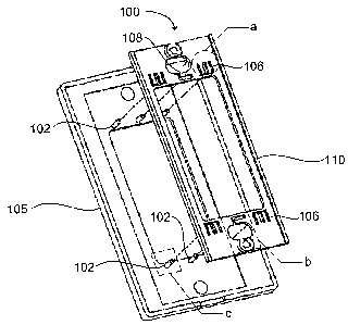
FIG. 1 is a perspective exploded view of a faceplate attachment system having
a center-finger socket in accordance with an embodiment of the present
invention;
FIG. 1 a is a magnified perspective view of an interference-fit-socket circled
in
"a" of FIG. 1;
FIG. lb is a magnified perspective view of another embodiment of an
interference-fit socket outlined in "b" of FIG. 1;
FIG. 1c is a magnified perspective view of a post outlined in "c" of FIG. 1;
FIG. 2a is a perspective view of the faceplate attachment system of FIG. 1;
FIG. 2b is a rear view of the faceplate attachment system of FIG. 1;
FIG. 3 is a perspective exploded view of a faceplate attachment system having
a center hole socket in accordance with an embodiment of the present
invention;
FIG. 3a is a magnified perspective view of a center-hole socket circled in "a"
of FIG. 3; and
FIG. 4 is a perspective view of the faceplate attachment system of FIG. 3-
DETAILED DESCRIPTION
Reference will now be made to the exemplary embodiments illustrated in the
drawings, and specific language will be used herein to describe the same. It
will
nevertheless be understood that no limitation of the scope of the invention is
thereby
intended. Alterations and further modifications of the inventive features
illustrated
herein, and additional applications of the principles of the inventions as
illustrated
herein, which would occur to one skilled in the relevant art and having
possession of
this disclosure, are to be considered within the scope of the invention.
An example embodiment, as illustrated in FIG. 1, provides a faceplate
attachment system 100 that consists of a plurality of posts 102 extending
perpendicularly from the back side of a faceplate 105 which mates with a
corresponding number of interference-fit sockets 106 located in a sub-plate
110.
CA 02557141 2006-08-22
WO 2005/082058 PCT/US2005/006152
3
Each interference-fit socket 106 can include a post opening 125 in the
faceplate which has a width less than a width of the diameter of the post, as
shown in
FIG. 1 a, which shows a magnified view of one embodiment of an interference-
fit
socket circled in "a" in FIG. 1. The post opening can be located adjacent to
one or
more interference fingers 120. Each interference finger can include a first
side 122
and a second side 124. The first side can face the post opening while the
second side
can face an area 130 that is substantially open for at least a portion of the
length of the
interference finger. The first side may also have an open area 133 that is
substantially
open for a portion of the length of the interference finger.
An interference-fit socket 108 may also be formed using a single interference
finger 140, as shown in FIG. lb, which shows a magnified view of a single-
finger
socket outlined in "b" in FIG. 1. A post opening 145 may be located at the
distal end
of the interference finger 140 relative to the sub-plate 110 or at another
advantageous
location on the finger. Open areas 150 and 160, may be substantially open for
the
length of the interference finger, wherein the open areas are located adjacent
to the
interference finger.
The interference-fit aspect of this mating system is utilized when inserting a
post 102 having an outer diameter slightly larger than the inner diameter of
the post
opening 125. Insertion of the post forces the somewhat flexible interference
fingers
120 to flex outwardly away from the post. This provides spring tension or back
pressure on the post, thus holding the post in place.
The embodiments of the faceplate attachment system provide several
advantages: 1) the system is a simple, robust, and cost-effective mating
system that is
easy to tool for an injection-molding process; 2) once the post is inserted
into the
socket beyond the tapered section of the post, the insertion force and
retention ability
is substantially constant with depth; 3) the insertion and retention forces
can easily be
modified in the design process by changing the geometries of the socket
features
and/or by changing the material composition; 4) in contrast to many prior
systems, the
faceplate can be "snugged" up against walls of varying depths, and even
against walls
of varying flatness since the depth of insertion of each post can be somewhat
different
(within the limits of distorting the flatness of the somewhat flexible
faceplate); 5) the
mated pieces form a more mechanically integrated system versus prior known
systems, and thus reduces rattle; 6) the faceplate can be quite secure, yet
allow for
CA 02557141 2006-08-22
WO 2005/082058 PCT/US2005/006152
4
easy removal by the user, and 7) given an appropriate material, its retention
force can
remain substantially constant for many years.
Returning to FIG. 1, each post 102 can extend perpendicular from the
faceplate 105. The post can be positioned and sized such that, as the
faceplate is
coupled to the sub-plate 110, the post can be received into the post opening
125 (FIG.
1 a) in the interference-fit socket 106 and engaged by the one or more
interference
fingers 120 (FIG. 1 a), enabling the faceplate to be securely mounted to the
sub-plate.
The one or more interference fingers are configured to flex away from the post
as the
post is received, providing spring tension on the post to apply resistance to
movement
of the faceplate when the post is engaged by the one or more interference
fingers.
The post opening can be formed from an indention in one or more interference
fingers. For example, in the embodiment shown in FIG. 1 a, wherein the
interference-
fit socket 106 comprises two fingers, the post opening 125 is formed from
indentations in the interference fingers at a distal end of the fingers
relative to the sub-
plate. A third indentation is also formed in the sub-plate across from and
between the
two fingers. Together, the three indentations form a circular area to guide
the post as
it is received by the interference-fit socket.
Another example of a post opening is shown in the embodiment in FIG. lb,
wherein the interference-fit socket 108 comprises one finger. The post opening
145 is
formed from an indentation in the finger 140 and an indentation in the sub-
plate
directly across from the finger indentation. The two indentations form a
circular area
to guide the post, as in FIG. la. The post opening does not need to be
circular. Any
shape of post opening may be used which can enable the post to be guided into
the
interference-fit socket. The post opening may have an oval, square,
rectangular,
triangular, octagonal, or some other polygonal shape.
While the post opening is shown in an end of the one or more interference
fingers that is distal to the sub-plate, it is also possible for the post
opening to be
located near a middle of the one or more interference fingers. The post
opening may
even be located near a proximal end of the interference fingers, opposite the
distal
end, where the fingers are attached to the sub-plate. The placement of the
post
opening can be determined by the desired resistance to be applied by the
fingers and
the characteristics of the material used to form the sub-plate and
interference fingers,
such as strength, elasticity, brittleness, and other relevant factors.
CA 02557141 2006-08-22
WO 2005/082058 PCT/US2005/006152
Referring to FIG. 1 c, the distal end 162 of each post 102 can be tapered 160
to
easily allow initial alignment and insertion into the interference-fit socket.
Beyond
the tapered end, each post may have a substantially consistent diameter for
the
remaining length of the post down to the proximal end 164 of the post where it
5 attaches to the faceplate 105. In another embodiment, the entire post can be
tapered.
The post may have a substantially smooth surface. In another embodiment, the
post
may be formed with grooves, or a roughened surface to increase the amount of
resistance in movement between the post and the interference fingers. Each
post can
have a width or outer diameter 170 which enables a predetermined amount of
resistance to occur when the post is engaged by the one or more interference
fingers.
A single sub-plate may have a plurality of interference-fit sockets that are
all
substantially similar, or there may be two or more different types of
interference-fit
sockets. For example, FIG. 2a shows one embodiment of a faceplate attachment
system 200 wherein the faceplate 105 is coupled to the sub-plate 110 using six
interference-fit sockets. Four of the interference sockets 106 each have two
interference fingers and are located in the four corners of the sub-plate. Two
of the
interference sockets 108 each have one interference finger and are located
near the
center of the sub-plate on opposite ends. Six posts 102 extend perpendicular
from the
faceplate. The posts are positioned on the faceplate and sized such, that as
the
faceplate is coupled to the sub-plate, the posts are received into the post
opening in
the interference-fit sockets and engaged by the one or more interference
fingers in
each of the interference sockets. By engaging the posts in the interference-
fit sockets,
the faceplate can be securely mounted to the sub-plate.
FIG. 2b shows a back orthogonal view of a faceplate attachment system 200 of
FIG 2a. Each of the six posts 102 are visible as they extend through the post
openings
125, 145 (FIG. l a, lb) in each of the interference-fit sockets 106, 108
respectively.
The posts are positioned on the faceplate 105 such that they will align with
the
interference-fit sockets and engage the interference fingers 120, 140 (FIG.
la, lb)
when the faceplate is coupled to the sub-plate 110. The interference fingers
can be
formed of a material (e.g. plastic or metal) which will enable them to flex
and provide
resistance to movement of the posts, and thus the faceplate.
Another embodiment comprises a faceplate attachment system 300 having a
center-hole guide 308, as shown in FIG. 3. The center-hole guide can be used
to help
CA 02557141 2011-10-11
69912-643
6
align the posts 102 into the interference-fit sockets 106. In one embodiment,
one or
more center-hole posts 103 can be configured to fit into one or more center-
hole
guides 308, 310, wherein the center-hole posts are substantially similar to
the one or more
posts used in conjunction with the interference-fit sockets 106. In another
embodiment, the center-hole posts used to fit into the one or more center-hole
guides
can be a different type of post than the posts used to mate with the
interference-fit
sockets.
The faceplate 105 can be coupled to the sub-plate 110 by mating the posts
102 with the one or more interference-fit sockets 106 and mating the one or
more
center-hole posts 103 with the one or more center-hole guides 308. FIG. 3a
shows a
magnified view of the center-guide hole outlined in "a" in FIG. 3. A center-
hole post
can be received through the guide hole 308. The center hole-post and center-
hole
guide can be used to align the faceplate to the sub-plate so that the posts
102 will
correctly mate with the interference-fit sockets 106.
In an additional embodiment, the center hole guide may be an interference
socket also. In particular, the center hole may have a beam or finger that is
fixed on
both ends or the finger may have a free end. Even though a single finger or
beam in
the center hole may not have a free end and may not flex as much as an
interference
finger with a free end, the interference finger can still contribute to
holding the
faceplate.
FIG. 4 shows one embodiment of a faceplate attachment system 400 wherein
the faceplate 105 is coupled to the sub-plate 110 using four interference-fit
sockets
106 and two center-hale guides 308. The four interference sockets 106 each
have two
interference fingers and are located in the four comers of the sub-plate. The
two
center-hole guides 308 are located near the center of the sub plate on
opposite sides.
Four posts 102 extend from the faceplate and are aligned with the four
interference
sockets. Two center-hole posts 103 also extend from the faceplate at a
position to
mate with the center-hole guides and enable the four posts to be better
aligned with
the interference-fit-sockets. The posts are positioned on the faceplate and
sized such
that as the faceplate is coupled to the sub-plate, the posts are received into
the post
opening in the interference-fit socket and engaged by the one or more
interference
fingers in each of the interference sockets. By engaging the posts in the
interference-
fit sockets, the faceplate can be securely mounted to the sub-plate.
CA 02557141 2011-10-11
69912-643
7
The interference-fit sockets can be simply formed in plastic having some
characteristic of flexibility. Examples of plastic that can be used are Delrin
or ABS
(which includes any of a class of plastics based on acrylonitrile-butadiene-
styrene
copolymers). The generic term for Derin is acetal resin.
The number, shape, and placement of interference fingers can be changed to
achieve varying insertion and retention forces. The number, shape, and
placement of
posts can be changed as well. Posts made of another material, such as spring
steel,
inserted into a post opening could accomplish the same purpose, but at the
expense of
added cost and complexity.
This discussion has been defined using the term "interference-fit socket", but
there are a number of technical terms that could reasonably describe the
interaction
between the post and socket. For example, end products in which the invention
may
be used are products purchased by home owners, home automation users,
government
facilities, commercial installations, or any other location desiring an
effective and
aesthetic face plate mounting system.
It is to be understood that the above-referenced arrangements are only
illustrative of the application for the principles of the present invention.
Numerous
modifications and alternative arrangements can be devised without departing
from the
spirit and scope of the present invention. While the present invention has
been shown
in the drawings and fully described above with particularity and detail in
connection
with what is presently deemed to be the most practical and preferred
embodiment(s)
of the invention, it will be apparent to those of ordinary skill in the art-
that numerous
modifications can be made without departing from the principles and concepts
of the
invention as set forth herein.