Note : Les descriptions sont présentées dans la langue officielle dans laquelle elles ont été soumises.
CA 02558485 2006-09-07
WO 2005/086807 PCT/US2005/007554
LOW ENERGY FLUID ACTUATOR CONTROL ELEMENT
BACKGROUND
Field of the Invention:
The present invention generally relates generally to the field of fluid
control elements. More particularly, the present invention relates to the
field of
low-energy electrical water flow control devices that conserve energy and
reduce
the waste of water.
Description of the Related Art:
Automatic faucets have become popular for a variety of reasons. They
save water, because water can be run only when needed. For example, with a
conventional sink faucet, when a user washes their hands the user tends to
turn on
the water and let it run continuously, rather than turning the water on to wet
their
hands, turning it off to lather, then turning it back on to rinse. In public
bathrooms
the ability to shut off the water when the user has departed can both save
water
and help prevent vandalism.
One early version of an automatic faucet was simply a spring-controlled
faucet, which returned to the "off" position either immediately, or shortly
after,
the handle was released. The former were unsatisfactory because a user could
only wash one hand at a time, while the later proved to be mechanically
unreliable.
A better solution were hands-free faucets. These faucets employed a
proximity detector and an electric power source to activate water flow without
the
need for a handle. In addition to helping to conserve water and prevent
vandalism, hands-free faucets also had additional advantages, some of which
began to make them popular in homes, as well as public bathrooms. For example,
there is no need to touch the faucet to activate it; with a conventional
faucet, a
user with dirty hands may need to wash the faucet after washing their hands.
In
CA 02558485 2012-02-02
WO 2005/086807 PCTIUS2005/007554
2
public facilities non-contact operation is also more sanitary. Hands-free
faucets
also provide superior accessibility for the disabled, or for the elderly, or
those who
need assisted care.
Typically, these faucets use active infra-red ("lR") detectors in the form of
photodiode pairs to detect the user's hands (or other objects positioned in
the sink
for washing). Pulses of IR light are emitted by one diode with the other being
used to detect reflections of the emitted light off an object in front of the
faucet.
Different designs use different locations on the spout for the photodiodes,
including placing them at the head of the spout, farther down the spout near
its
base, or even at positions entirely separate from the spout.
For both safety and cost reasons it is preferable to use battery power to
operate hands-free faucets, so power consumption is an important design
consideration. Because the detection devices require very little power to
operate,
the most significant power consumption comes from the mechanical operation of
the valve to physically regulate the flow of water.
Naturally, the mechanical operation of the valve must be suitable for
electronic control, since it must be responsive to the output of the IR
detectors.
Proportional control valves provide a useful means for electronic control of
the
valve mechanism. An example of a proportional control valve mechanism (used
to control fluid flow in a water heater) is disclosed in U.S. Patent No.
5,020,771 to
Nakatsukasa.
Figure 1 is a diagram of a proportional control valve mechanism, indicated
generally at 100. The proportional control valve mechanism 100 includes a main
valve 120, which provides the main mechanical control of the flow, and a pilot
valve 140, which is used to regulate the main valve 120. Fluid enters the
proportional control valve mechanism 100 at 101, and travels through a main
passageway 103, which leads to a first chamber 110.
The chamber is defined in part by the main valve 120, and by a first side of
a diaphragm 112 that is approximately the same size as the main valve 120
opposite the main valve 120. The diaphragm 112 is connected to the main valve
120 by a shaft 122. Because the main valve 120 and the diaphragm 112 are
CA 02558485 2006-09-07
WO 2005/086807 PCT/US2005/007554
3
approximately the same size, pressure in the chamber 110 results in an equal
and
opposite force on the shaft 122.
A portion of the main flow is diverted to the pilot valve 140 through a first
bypass passageway 105. The pilot valve 140 is connected to a solenoid 142,
which operates the pilot valve 140 in response to an electronic signal, such
as a
dithered pulse-width modulated ("PWM") signal.
When the pilot valve 140 is open, the diverted flow passes through a
second bypass passageway 107 into a second chamber 109. The second chamber
109 is defined in part by a second side of the diaphragm 112, opposite the
first
chamber 110, and contains an orifice 111 that permits the diverted fluid to
return
to the main flow downstream of the main valve 120. Consequently, when the
pilot valve 140 is opened pressure on the second side of the diaphragm
generates
force that disturbs the balance of forces on the shaft 122 from the pressure
within
the first chamber 110. The magnitude of the pressure in the second chamber 109
is a function of the size of the orifice 111 and the size of the aperture
created by
opening the pilot valve 140. Thus, the net force on the shaft 122, and hence
how
far it will deform the diaphragm 112 and open the main valve 140, can be
controlled by controlling the flow through the pilot valve 140.
Because the pilot valve can be substantially smaller than the main valve, it
can experience less force from the fluid pressure, and require less energy to
actuate. Furthermore, even a relatively small displacement in the pilot valve
140
can produce enough pressure to cause a substantial displacement in the main
valve
120. Consequently, the actuation of the pilot valve 140 requires substantially
less
power than it would require to actuate the main valve 120.
Nevertheless, the proportional control valve mechanism 100 requires
continuous power in order to maintain flow. When power to the solenoid 142 is
cut, the diverted flow forces the pilot valve 140 closed. Since the second
chamber
109 has an orifice, fluid will exit through it until there is no internal
pressure.
Consequently, the diaphragm 112 returns to its undeformed position, and the
main
valve is closed. In applications in which power is supplied by batteries, the
continuous draw of power to maintain flow leads to the need to replace
batteries
relatively frequently.
CA 02558485 2006-09-07
WO 2005/086807 PCT/US2005/007554
4
Thus, what is needed is a means to regulate the flow of water in a hands-
free faucet which draws very little power, to reduce the frequency with which
batteries must be replaced. In particular, there is a need for a means to
regulate
the flow of water in a hands-free faucet which does not draw power during
steady-
state operation-that is, it only draws power to change the flow rate. The
present
invention is directed towards meeting these needs, among others.
CA 02558485 2006-09-07
WO 2005/086807 PCT/US2005/007554
SUMMARY OF THE INVENTION
A low-energy fluid actuator control element according to the present
invention provides a means for electronic control of a fluid flow, such as is
needed
5 for hands-free water faucets, that will require a less frequent changing of
batteries.
A control element according to the present invention requires very little
power to
change the rate of fluid flow and, once a flow rate is established, requires
no
power at all to maintain that flow rate. In the preferred embodiment, even if
power is interrupted the control element will shut off fluid flow, so the
controlled
valve will not be stuck in an open position.
In a first embodiment, a fluid actuator for regulating fluid flow according
to the present invention comprises: a main fluid passageway, a main valve, a
chamber, and a pilot valve. The main fluid passageway is defined at least in
part
by a diaphragm, which has an inside facing inwardly relative to the main
passageway, and an outside facing outwardly relative to the main passageway.
The main valve is disposed to inhibit fluid flow through the main fluid
passageway, and is connected to the diaphragm by a rigid member. The main
valve is disposed to open outwardly from the main fluid passageway, such that
pressure within the main passageway tends to hold the main valve closed, and
pressure on the outside of the diaphragm tends to push open the main valve.
The
chamber is defined in part by the outside of the diaphragm. The pilot valve
comprises: an input passageway, an output passageway, a rotatable shaft
disposed
between them, a permanent magnet affixed to the rotatable shaft, an
electromagnet, a control element, and a failsafe magnet. The input passageway
diverts a portion of the fluid flow from the main fluid passageway, and the
output
passageway directs the diverted portion of the fluid flow to the chamber. The
rotatable shaft has a slot therein that gives the rotatable shaft a varied
cross-
section as a function of its angular position. The slot is disposed to permit
fluid to
flow between the input passageway and the output passageway except when the
rotatable shaft is in a closed position. The electromagnet is disposed to
generate
first magnetic field that, via the permanent magnet, drives the rotatable
shaft away
from the closed position. The control element places a dithered PWM current on
CA 02558485 2006-09-07
WO 2005/086807 PCT/US2005/007554
6
the electromagnet, such that the length of the duty cycle controls the
strength of
the first magnetic field. The failsafe magnet disposed to generate a second
magnetic field that drives the rotatable shaft away from the closed position.
In a second embodiment, a pilot valve according to the present invention
comprises: an input passageway, an output passageway, a rotatable shaft
disposed
between them, a permanent magnet affixed to the rotatable shaft, an
electromagnet, a control element, and a failsafe magnet. The rotatable shaft
has a
slot therein that gives the rotatable shaft a varied cross-section as a
function of its
angular position. The slot is disposed to permit fluid to flow between the
input
passageway and the output passageway except when the rotatable shaft is in a
closed position. The electromagnet is disposed to generate first magnetic
field
that, via the permanent magnet, drives the rotatable shaft away from the
closed
position. The control element places a dithered PWM current on the
electromagnet, such that the length of the duty cycle controls the strength of
the
first magnetic field. The failsafe magnet is disposed to generate a second
magnetic field that drives the rotatable shaft away from the closed position.
In a third embodiment, a hands-free water faucet according to the present
invention comprises: at least one main water passageway, a flap valve, a
chamber,
and a pilot valve. The at least one main water passageway is defined at least
in
part by a diaphragm having an inside facing inwardly relative to the main
passageway, and an outside facing outwardly relative to the main passageway.
The flap valve is disposed to inhibit fluid flow through the at least one main
water
passageway, and is connected to the diaphragm by a rigid member. The flap
valve
is disposed to open outwardly from the main fluid passageway, such that
pressure
within the main passageway tends to hold the flap valve closed, and pressure
on
the outside of the diaphragm tends to push open the flap valve. The chamber is
defined in part by the outside of the diaphragm. The pilot valve comprises: an
input passageway, an output passageway, a rotatable shaft between them, a
permanent magnet affixed to the shaft, an electromagnet, a control element,
and a
failsafe magnet. The input passageway diverts a portion of water flow from the
at
least one main water passageway. The output passageway directs the diverted
portion of the water flow to the chamber. The rotatable shaft has a slot
therein
CA 02558485 2006-09-07
WO 2005/086807 PCT/US2005/007554
7
that gives the rotatable shaft a varied cross-section as a function of its
angular
position. The slot is disposed to permit water to flow between the input
passageway and the output passageway except when the rotatable shaft is in a
closed position. The electromagnet is disposed to generate a first magnetic
field
that, via the permanent magnet, drives the rotatable shaft away from the
closed
position. The control element places a current signal on the electromagnet
that
controls the strength of the first magnetic field. The failsafe magnet
disposed to
generate a second magnetic field that drives the rotatable shaft away from the
closed position.
CA 02558485 2006-09-07
WO 2005/086807 PCT/US2005/007554
8
BRIEF DESCRIPTION OF THE DRAWINGS
Although the characteristic features of this invention will be particularly
pointed out in the claims, the invention itself, and the manner in which it
may be
made and used, may be better understood by referring to the following
descriptions taken in connection with the accompanying figures forming a part
hereof.
Figure 1 is a cross sectional view of a prior art proportional control valve
mechanism.
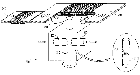
Figure 2 is an illustration of a preferred embodiment low-energy fluid
actuator control element according to the present invention.
CA 02558485 2006-09-07
WO 2005/086807 PCT/US2005/007554
9
DETAILED DESCRIPTION OF THE PREFERRED EMBODIMENT
For the purposes of promoting an understanding of the principles of the
invention, reference will now be made to the preferred embodiment and specific
language will be used to describe the same. It will nevertheless be understood
that
no limitation of the scope of the invention is thereby intended. Such
alternations
and further modifications in the invention, and such further applications of
the
principles of the invention as described herein as would normally occur to one
skilled in the art to which the invention pertains, are contemplated, and
desired to
be protected.
A low-energy fluid actuator control element according to the present
invention provides a means for electronic control of a fluid flow, such as is
needed
for hands-free water faucets, that will require less frequent changing of
batteries.
A control element according to the present invention requires little power to
change the rate of fluid flow and, once a flow rate is established, requires
no
power at all to maintain that flow rate. In the preferred embodiment, even if
power is interrupted the control element will shut off fluid flow, so the
controlled
valve will not be stuck in an open position.
Figure 2 illustrates a preferred embodiment pilot valve suitable for use in a
proportional control valve controlled hands-free faucet, indicated generally
at 200.
The pilot valve 200 receives a diverted flow through a input passageway 203,
which is partially blocked by a variable slotted shaft 210, and outputs the
diverted
flow through an output passageway 205. The input passageway 203 and output
passageway 205 are preferably on the order of 40-50 one-thousandths of an inch
in diameter, while the variable slotted shaft is preferably on the order of 50-
60
one-thousands of an inch in diameter. The output flow can be used to control a
main valve by putting pressure on a diaphragm, analogously to the flow through
the second bypass passageway 107 in the proportional control valve mechanism
100.
The variable slotted shaft 210 has a notch or slot 212 in it, such that as it
is
rotated, it presents a variable sized cross section. When the slot 212 is
positioned
perpendicularly to the input passageway 203 flow it completely closes off the
CA 02558485 2006-09-07
WO 2005/086807 PCT/US2005/007554
flow; as it is rotated the cross section of the slot increases to permit
greater flow,
until a minimum pressure drop and maximum flow is reached at 90 degrees
displacement. It will be appreciated that a hole can be used in lieu of a
notch or
slot; the specific shape of the cross section of the variable slotted shaft
210 is
5 unimportant, so long as it presents a variable cross section as a function
of its
angular position with respect to the center line of input passageway 203.
It will be appreciated that the pressure from the fluid passing the variable
slotted shaft is approximately symmetrical; i.e., the torque on the variable
slotted
shaft 210 produced by the water pressure on one side of its axis of rotation
is the
10 same as the torque on the other side of its axis of rotation. Although
pressure
differences resulting from different differential flow rates or from
turbulence near
the surface of the slot 212 could conceivably destroy the symmetry of torque,
any
small amount of resulting torque is outweighed by friction. Consequently, when
no external force is applied on the variable slotted shaft 210 it will remain
in its
present position, regardless of the flow rate. Thus, once positioned, no
energy is
required to maintain the variable slotted shaft 210 in its position.
Although the input passageway 203 and output passageway 205 are
preferably axially aligned, this is not necessary. For example, these
passageways
can be perpendicularly aligned with respect to each other and the variable
slotted
shaft 210. Any arrangement in which the flow from the input passageway 203 to
the output passageway 205 may be used, though it will be appreciated that the
shape of the slot 212 must be selected to permit the flow to be arrested in at
least
one closed position, and preferably to provide a monotonically increasing flow
through some range of angular displacement of slotted shaft 210 away from a
closed position.
In the presently preferred embodiment the variable slotted shaft 210 is
affixed to a permanent magnet 220, which is actuated by an electromagnet 230.
Referring to Figure 2, the permanent magnet 220 and variable slotted shaft are
oriented such that, when the permanent magnet 220 is aligned as shown the slot
212 is perpendicular to the passageways 203 and 205, such that fluid flow is
completely shut off.
CA 02558485 2006-09-07
WO 2005/086807 PCT/US2005/007554
11
The electromagnet 230 is regulated by a dithered PWM signal. The
dithered PWM signal permits the generation of a variable-strength magnetic
field
that will drive the variable slotted shaft 210 (via the permanent magnet 220)
away
from the closed position shown in Figure 2.
An opposing magnetic field tends to drive the variable slotted shaft 210
back towards the closed position. The opposing magnetic field can be supplied
in
a number of ways. In certain embodiments, a failsafe permanent magnet 240 is
positioned in the vicinity, oriented as shown in Figure 2. Alternatively, the
failsafe magnet 240 can be an electromagnet. The PWM signal can be used to
direct a DC current through the coils of the electromagnet 230 during the on-
duty
portions of the cycle, and through the oppositely wound coils of the failsafe
magnet 240 during the off-duty portions of the cycle. In still other
alternatives,
the failsafe magnet 240 and electromagnet can be combined into a single
electromagnet, and the direction of DC current through the coils can be
reversed
during off-duty and on-duty portions of the cycle, for example using
transistor
switches, as is known in the art.
In those embodiments that lack a permanent failsafe magnet 240 an
alternative failsafe mechanism is preferably included in the circuitry
controlling
the electromagnet 230. For example, a capacitor failsafe system, such as are
known in the art, can be used. In such systems, a capacitor is held charged by
the
DC current that powers the electromagnet 230 during the on-duty portions of
the
cycle. When power is lost, the power in the capacitor can be discharged to
power
the electromagnet 230 in the opposite polarity long enough to return the
variable
slotted shaft 210 to the closed position.
It will be appreciated that a hands-free water faucet can employ a pair of
low-energy fluid actuator control elements according to the present invention
in
order to regulate a hot and cold water supplies independently, as a means to
regulate the temperature of water discharged from a single spout. In such
applications the PWM signal that corresponds to the proper flow rate for the
hot
and cold water supplies can be retained in electronic memory and used as
default
values when an IR detector activates the faucet.
CA 02558485 2012-02-02
WO 2005/086807 PCUS2005/007554
12
While the invention has been illustrated and described in detail in the
drawings and foregoing description, the description is to be considered as
illustrative and not restrictive in character. Only the preferred embodiments,
and
such alternative embodiments deemed helpful in further illuminating the
preferred
embodiment, have been shown and described. Variations and modifications exist
as
would be apparent to a person skilled in the art. Accordingly, the scope of
the
claims should not be limited to the preferred embodiments set forth in the
examples,
but should be given the broadest interpretation consistent with the
description as a
whole.