Sélection de la langue

Search

Sommaire du brevet 2558681 

Énoncé de désistement de responsabilité concernant l'information provenant de tiers

Une partie des informations de ce site Web a été fournie par des sources externes. Le gouvernement du Canada n'assume aucune responsabilité concernant la précision, l'actualité ou la fiabilité des informations fournies par les sources externes. Les utilisateurs qui désirent employer cette information devraient consulter directement la source des informations. Le contenu fourni par les sources externes n'est pas assujetti aux exigences sur les langues officielles, la protection des renseignements personnels et l'accessibilité.

Disponibilité de l'Abrégé et des Revendications

L'apparition de différences dans le texte et l'image des Revendications et de l'Abrégé dépend du moment auquel le document est publié. Les textes des Revendications et de l'Abrégé sont affichés :

  • lorsque la demande peut être examinée par le public;
  • lorsque le brevet est émis (délivrance).
(12) Brevet: (11) CA 2558681
(54) Titre français: METHODE ET DISPOSITIF FOURNISSANT UN SUPPORT TEMPORAIRE DE TENSION DES CONDUCTEURS DE CIRCUITS DE TRANSMISSION OU DE DISTRIBUTION
(54) Titre anglais: A METHOD AND APPARATUS FOR PROVISION OF TEMPORARY CONDUCTOR TENSION SUPPORT IN TRANSMISSION OR DISTRIBUTION CIRCUITS
Statut: Accordé et délivré
Données bibliographiques
(51) Classification internationale des brevets (CIB):
  • H02G 7/05 (2006.01)
  • H02G 1/04 (2006.01)
(72) Inventeurs :
  • O'CONNELL, DANIEL N. (Canada)
  • DEVINE, CLIFFORD W. (Canada)
(73) Titulaires :
  • QUANTA ASSOCIATES, L.P.
(71) Demandeurs :
  • QUANTA ASSOCIATES, L.P. (Etats-Unis d'Amérique)
(74) Agent: ANTONY C. EDWARDSEDWARDS, ANTONY C.
(74) Co-agent:
(45) Délivré: 2014-11-04
(22) Date de dépôt: 2006-08-30
(41) Mise à la disponibilité du public: 2008-02-29
Requête d'examen: 2011-08-24
Licence disponible: S.O.
Cédé au domaine public: S.O.
(25) Langue des documents déposés: Anglais

Traité de coopération en matière de brevets (PCT): Non

(30) Données de priorité de la demande: S.O.

Abrégés

Abrégé français

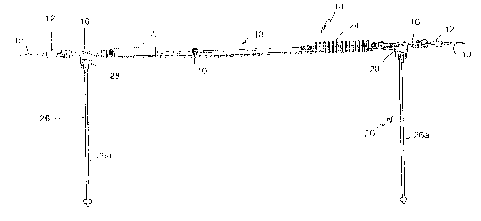
Un ensemble de support de conducteurs comprend une paire de fourches qui possèdent une paire de câbles qui sétendent entre lesdites fourches de manière parallèle et espacée. Des actionneurs tendent les câbles de façon à étirer sélectivement les fourches lune vers lautre le long des câbles. Des éléments dattache coopèrent avec les fourches pour monter ces dernières en relation espacée sur et le long dun segment conducteur dun conducteur à utiliser de façon à étendre ledit segment conducteur le long des fourches et à une position sensiblement médiane entre lesdites fourches. Létirement des fourches lune vers lautre permet de réduire la tension sur le segment conducteur en vue dune réparation ou dune utilisation.


Abrégé anglais

A conductor supporting assembly includes a pair of yokes having a pair of cables extending therebetween in spaced parallel array. Actuators tension the cables so as to selectively draw the yokes toward each other along the cables. Grips cooperate with yokes for mounting the yokes in spaced apart array to and along a conductor segment of a conductor to be serviced so as to extend the conductor segment along and substantially medially between the yokes. The drawing of the yokes toward each other thereby de-tensions the conductor segment to allow for repair or service.

Revendications

Note : Les revendications sont présentées dans la langue officielle dans laquelle elles ont été soumises.


WHAT IS CLAIMED IS:
1. A conductor supporting assembly comprising:
an opposed-facing pair of first and second tension supports having a parallel
pair of
flexible first and second elongate members extending therebetween in spaced
parallel
array, a means for tensioning said first and second elongate members so as to
selectively
draw said first and second tension supports toward each other, first and
second conductor
mounts cooperating with said first and second tension supports for mounting
said first and
second tension supports in spaced apart array to and along a conductor segment
of a
conductor to be serviced so as to extend the conductor segment along and
substantially
medially between said first and second elongate members, whereby said drawing
of said
first and second tension supports toward each other de-tensions the conductor
segment to
allow for the service, and further comprising at least one elongate insulated
tool mountable
to a corresponding tension support so as to depend downwardly therefrom and
stabilize the
mounting of said corresponding tension support onto the conductor segment.
2. The assembly of claim 1 wherein said tension supports are yoke
assemblies.
3. The assembly of claim 2 wherein each yoke assembly of said yoke
assemblies include a
rigid spreader element extending orthogonally between said elongate members.
4. The assembly of claim 3 wherein said each yoke assembly is a rigid yoke.
5. The assembly of claim 3 wherein said each yoke assembly includes a
flexible sling
extending from a corresponding said spreader element.
6. The assembly of claim 3 wherein said each spreader element is adjustable
along its length
so as to selectively adjust a spacing between said elongate members.
8

7. The assembly of claim 2 wherein said yoke assemblies are substantially
planar.
8. The assembly of claim 1 wherein said tension supports are yoke
assemblies each including
a rigid spreader element, and wherein said tool mounts underneath, in
cooperation with,
said spreader element.
9. The assembly of claim 1 further comprising at least one insulator
mounted in cooperation
with and between said elongate members and said tension supports.
10. A method of supporting a conductor comprising the steps of:
a) providing an opposed-facing pair of first and second tension supports
having a
parallel pair of flexible first and second elongate members extending
therebetween
in spaced parallel array,
b) providing at least one elongate insulated tool,
c) using said tool to install first and second conductor mounts cooperating
with said
first and second tension supports and mounting said first and second tension
supports in
spaced apart array to and along a conductor segment of a conductor to be
serviced so as to
extend the conductor segment along and substantially medially between said
first and
second elongate members, said tool being mountable to a corresponding tension
support so
as to depend downwardly therefrom and stabilize the mounting of said
corresponding
tension support onto the conductor segment,
d) providing a means for tensioning said first and second elongate members
and
selectively drawing said first and second tension supports toward each other,
so as to de-
tension the conductor segment to allow for the service.
9

11. The method of claim 10 wherein said tension supports are yoke
assemblies.
12. The method of claim 11 wherein each yoke of said yoke assemblies
include a rigid
spreader element extending orthogonally between said elongate members.
13. The method of claim 12 wherein said each yoke assembly is a rigid yoke.
14. The method of claim12 wherein said each yoke assembly includes a
flexible sling
extending from a corresponding said spreader element.
15. The method of claim 12 wherein said each spreader element is adjustable
along its length
so as to selectively adjust a spacing between said elongate members.
16. The method of claim 11 wherein said yoke assemblies are substantially
planar.
17. The method of claim 10 wherein said tension supports are yoke
assemblies each including
a rigid spreader element, and wherein said tool mounts underneath, in
cooperation with,
said spreader element.
18. The method of claim 10 further comprising at least one insulator
mounted in cooperation
with and between said elongate members and said tension supports.

Description

Note : Les descriptions sont présentées dans la langue officielle dans laquelle elles ont été soumises.


CA 02558681 2006-08-30
A METHOD AND APPARATUS FOR PROVISION OF TEMPORARY CONDUCTOR
TENSION SUPPORT IN TRANSMISSION OR DISTRIBUTION CIRCUITS
Field of the Invention
This invention relates to the field of repair and service to power
transmission
conductors and in particular to a method and apparatus for provision of
temporary conductor
tension support in transmission or distribution circuits.
Background of the Invention
The replacement of sleeves, dead end insulators, and conductor repair require
that
conductor tension be maintained or altered so that these processes can be
safely applied.
Often circumstances require the process to be done while the conductors are
energized and remain in service.
Present methods require use of conventional chain jacks, or rope blocks to
support
tension. These devices are heavy, cumbersome, difficult to install, and
because they are
conductive present a hazard in their application and use.
SummM of the Invention
In summary, the conductor supporting assembly according to the present
invention
may be characterized in one aspect as including an opposed-facing pair of
first and second tension
supports such as yokes having a parallel pair of flexible first and second
elongate members such as
cables extending therebetween in spaced parallel array, and a means such as
actuators for
1

CA 02558681 2006-08-30
tensioning the first and second elongate members so as to selectively draw the
first and second
tension supports toward each other. First and second conductor mounts such as
grips, cooperate
with the first and second tension supports for mounting the first and second
tension supports in
spaced apart array to and along a conductor segment of a conductor to be
serviced so as to extend
the conductor segment along and substantially medially between the first and
second elongate
members. At least one insulator is advantageously mounted in cooperation with
and between the
elongate members and the tension supports. The drawing of the first and second
tension supports
toward each other thereby de-tensions the conductor segment to allow for the
service.
In one embodiment the tension supports are yoke assemblies. The yoke
assemblies
may be substantially planar and may include a rigid spreader element extending
orthogonally
between the elongate members. Each yoke assembly may be a rigid yoke, or may
include a
flexible sling extending from a corresponding spreader element. The spreader
element may be
adjustable along its length so as to selectively adjust a spacing between the
elongate members.
At least one elongate insulated tool may be provided which is mountable to a.
corresponding tension support, for example a yoke, so as to depend downwardly
therefrom and
stabilize the mounting of the corresponding tension support onto the conductor
segment.
Advantageously, the tool mounts underneath, in cooperation with, the spreader
element.
The present invention also expressly includes within its ambit the
corresponding
method of producing, mounting or employing the conductor supporting assembly
described
sumrnarily above and in greater detail below. In particular the method
includes:
a) providing an opposed-facing pair_ of first and second tension supports such
as
yokes having a parallel pair of flexible first and second elongate members
such as
cables extending therebetween in spaced parallel array, and a means such as
2

CA 02558681 2006-08-30
actuators for tensioning the first and second elongate members so as to
selectively
draw the first and second tension supports toward each other,
b) providing first and second conductor mounts such as grips, which cooperate
with
the first and second tension supports and mounting the first and second
tension
supports in spaced apart array to and along a conductor segment of a conductor
to
be serviced so as to extend the conductor segment along and substantially
medially
between the first and second elongate members,
c) drawing the first and second tension supports toward each other to thereby
de-
tension the conductor segment to allow for the service.
In a further embodiment of the method, providing at least one elongate
insulated
tool and mounting the tool to a corresponding tension support, fqr example a
yoke, so as to depend
downwardly therefrom to stabilize the mounting of the corresponding tension
support onto the
conductor segment.
Brief DescritYtion of the DrawinLs
Figure 1 is, in plan view, the conductor supporting assembly according to one
embodiment of the present invention.
Figure 2 is, in front elevation view, the conductor supporting assembly
ofFigure 1.
Figure 3 is, in plan view, the conductor supporting assembly of Figure 1
mounted to
a conductor.
Figure 4 is, in front elevation view, the conductor supporting assembly of
Figure 3.
3

CA 02558681 2006-08-30
Figure 5 is, in front elevation view, the conductor supporting assembly of
Figure 4
tensioned so as to slacken the conductor between the opposed-facing pair of
yokes.
Figure 6 is, in front. elevation view, the conductor supporting assembly of
Figure 4
with an insulated tool mounted to, so as to depend downwardly from, the
corresponding yoke.
Figure 7 is, in plan view, the conductor supporting assembly of Figure 1 with
the
cable slings adjusted inwardly relative to the opposed-facing pair of yokes so
as to decrease the
spacing between the pair of parallel cable slings.
Figure 8 is, in front elevation view, the conductor supporting assembly
ofFigure 7.
Figure 9 is, in plan view, a further embodiment of the conductor supporting
assembly according to the present invention wherein the rigid triangular yoke
of the embodiment
of Figure 1 is replaced with a rigid spreader eleinent supported on a V-shape
cable sling.
Figure 10 is, in plan view, a further embodiment of the cable supporting
assembly
according to the present invention wherein the opposed-facing pair of rigid
yokes of Figure 1 are
replaced with a rigid spreader element of adjustable length supported by a V-
shape cable sling.
Figure 11 is, in side elevation view, a conductor hook assembly for use with
an
insulated tool for mounting under a yoke plate according to one embodiment of
the present
invention.
Figure 12 is, in front elevation view, the conductor hook assembly of Figure
11.
4

CA 02558681 2006-08-30
Figure 13 is, in side elevation view, the conductor hook assembly of Figure 11
mounted to the underside of the yoke plate of Figure 1.
Figure 14 is, in front elevation view, the conductor hook assembly of Figure
13
mounted onto a conductor.
Figure 15 is, in plan view, a further alternative embodiment according to the
present invention wherein the conductor supporting assembly is mounted to a
support slructure so
as to relieve the tension on a dead end insulator.
Figure 16 is, in front elevation view, the conductor supporting assembly of
Figure
16.
Figure 17 is, in front elevation view, the conductor supporting assembly of
Figure
17, tensioned so as to provide slack in the conductor mounted adjacent the
dead end insulator.
Detailed Description of Embodiments of the Invention
Conductor 10 is gripped or. secured by a single grip such as a conventional
conductor clamp 12 on each end 14a and 14b of the conductor support 14 so that
tension support
14 is in contact with conductor 10 throughout the length of the repair
operation Yokes 16 provide
an appropriate space di between the two points of attachment I6a and 16b to,
as tension is
established on, two cable slings 18. Conductor 10 is slackened between yokes
16 as slings 18 are
tensioned in directions A, that is to allow conductor 10 to lower in direction
B the cable slings 18,
thus providing a safe and convenient portion of conductor 10, now relieved
from tension, for what
ever repair or installation is required.
5

CA 02558681 2006-08-30
Thus tension support 14 consists of two yokes 16, whether they be the plates
illustrated in Figure 1 or the flexible cable and rigid spreader bar yokes of
Figure 9 or adjustable or
telescopic spreader bar and cable arrangements of Figure 10. One yoke 16 is
mounted at each end
of the length of conductor 10 to be supported, attached to the conductor with
an appropriate grip
12 through a shackle 20. Two hydraulic cylinders 22, or other mechanical
tensioning devices
tension cable slings 18 between the yokes 16. Cylinders 22 draw the two yokes
16 towards each
other, thus relieving tension on the conductor between the two yokes. The
cylinders or other
tension providing devices can be for example hydraulically, electrically, or
manually powered.
Cylinders 22 are mounted to a first yoke 16. The other, second yoke has two
insulators 24 mounted to ensure that no current flows through cable slings 18,
cylinders 22 or
other tension providing mechanism between yokes 16. The cable slings between
the two yoke
plates can be made as long or as short as the particular job requires, and
must have sufficient rated
strength to support the known tension that they will be subject to.
Both yokes 16and their corresponding assemblies can be applied or installed
using
an insulated tool 26 such as for example the wire tong illustrated. Tool 26 is
of sufficient length to
isolate the installer (not shown) from any electrical hazard. Once a yoke 16
is applied by for
example hooking conductor hook 28 over conductor 10 with yoke 16 mounted atop
the conductor
2 0 hook, this insulated tool 26 is left attached and acts as a pendulum so as
to keep the yoke 16
properly oriented, for example horizontal, to the conductor segment being
repaired or serviced. A
yoke 16 may be mounted atop conductor hook 28 by means of, for example, nut
and studs 30 and
32 respectively. Conductor hook 28 maybe mounted at the tong end of a work
pole 26aby means
of a bai134.
In order to provide a current path adequate to the applied load on the subject
conductor, a conventional parallel conductor (not shown) must be installed
around any intended
opening prior to interruption of the normal current path.
6
~~..~.

CA 02558681 2006-08-30
This apparatus can be installed on single or bundled conductors by means of
appropriate grips and clevises of adequate strength to support tension of all
sub conductors within
the bundle. Depending on the width of the conductor bundle (not shown) the
spacing d1 may be
increased to the full width allowed by the width of yoke 16 (or to which
spacing the yoke mav be
adjusted for the adjustable width yokes of Figure 10), or reduced such as seen
in Figure 7. For
example, a yoke width may be in the order of eighteen to twenty-four inches,
which is not intended
to be limiting. Sling assemblies including insulators 24 and cylinders 22 are
mounted by means of
adapter links 36 for example to a hole 16c in the corresponding array of holes
16c in spreader
element 16d of yokes 16.
The changing of dead end insulators 38 or dead end assemblies (not shown) can
be
achieved by the installation of yoke 16 containing the tensioning devices such
as cylinders 24 with
cable slings 18 providing support from support tower 40 or structure through
appropriate
insulating devices 42 applied in series with cable slings 18 and/or tensioning
devices 22.
As will be apparent to those skilled in the art in the light of the foregoing
disclosure, many alterations and modifications are possible in the practice of
this invention
without departing from the spirit or scope thereof. Accordingly, the scope of
the invention is to be
construed in accordance with the substance defined by the following claims.
7

Dessin représentatif
Une figure unique qui représente un dessin illustrant l'invention.
États administratifs

2024-08-01 : Dans le cadre de la transition vers les Brevets de nouvelle génération (BNG), la base de données sur les brevets canadiens (BDBC) contient désormais un Historique d'événement plus détaillé, qui reproduit le Journal des événements de notre nouvelle solution interne.

Veuillez noter que les événements débutant par « Inactive : » se réfèrent à des événements qui ne sont plus utilisés dans notre nouvelle solution interne.

Pour une meilleure compréhension de l'état de la demande ou brevet qui figure sur cette page, la rubrique Mise en garde , et les descriptions de Brevet , Historique d'événement , Taxes périodiques et Historique des paiements devraient être consultées.

Historique d'événement

Description Date
Paiement d'une taxe pour le maintien en état jugé conforme 2024-08-23
Requête visant le maintien en état reçue 2024-08-23
Représentant commun nommé 2019-10-30
Accordé par délivrance 2014-11-04
Inactive : Page couverture publiée 2014-11-03
Lettre envoyée 2014-08-28
Préoctroi 2014-08-22
Inactive : Taxe finale reçue 2014-08-22
Inactive : Transfert individuel 2014-08-19
Lettre envoyée 2014-02-25
Un avis d'acceptation est envoyé 2014-02-25
Inactive : Q2 réussi 2014-02-17
Inactive : Approuvée aux fins d'acceptation (AFA) 2014-02-17
Modification reçue - modification volontaire 2013-09-27
Inactive : Dem. de l'examinateur par.30(2) Règles 2013-03-27
Lettre envoyée 2011-09-09
Requête d'examen reçue 2011-08-24
Toutes les exigences pour l'examen - jugée conforme 2011-08-24
Exigences pour une requête d'examen - jugée conforme 2011-08-24
Demande publiée (accessible au public) 2008-02-29
Inactive : Page couverture publiée 2008-02-28
Inactive : Grandeur de l'entité changée 2007-02-22
Inactive : Lettre officielle 2007-02-22
Inactive : Paiement correctif - art.78.6 Loi 2007-01-24
Inactive : CIB attribuée 2006-12-04
Inactive : CIB en 1re position 2006-12-04
Inactive : CIB attribuée 2006-12-04
Inactive : Certificat de dépôt - Sans RE (Anglais) 2006-10-06
Exigences de dépôt - jugé conforme 2006-10-06
Demande reçue - nationale ordinaire 2006-10-04
Inactive : Demandeur supprimé 2006-10-04

Historique d'abandonnement

Il n'y a pas d'historique d'abandonnement

Taxes périodiques

Le dernier paiement a été reçu le 2014-08-27

Avis : Si le paiement en totalité n'a pas été reçu au plus tard à la date indiquée, une taxe supplémentaire peut être imposée, soit une des taxes suivantes :

  • taxe de rétablissement ;
  • taxe pour paiement en souffrance ; ou
  • taxe additionnelle pour le renversement d'une péremption réputée.

Veuillez vous référer à la page web des taxes sur les brevets de l'OPIC pour voir tous les montants actuels des taxes.

Titulaires au dossier

Les titulaires actuels et antérieures au dossier sont affichés en ordre alphabétique.

Titulaires actuels au dossier
QUANTA ASSOCIATES, L.P.
Titulaires antérieures au dossier
CLIFFORD W. DEVINE
DANIEL N. O'CONNELL
Les propriétaires antérieurs qui ne figurent pas dans la liste des « Propriétaires au dossier » apparaîtront dans d'autres documents au dossier.
Documents

Pour visionner les fichiers sélectionnés, entrer le code reCAPTCHA :


Pour visualiser une image, cliquer sur un lien dans la colonne description du document. Pour télécharger l'image (les images), cliquer l'une ou plusieurs cases à cocher dans la première colonne et ensuite cliquer sur le bouton "Télécharger sélection en format PDF (archive Zip)" ou le bouton "Télécharger sélection (en un fichier PDF fusionné)".

Liste des documents de brevet publiés et non publiés sur la BDBC .

Si vous avez des difficultés à accéder au contenu, veuillez communiquer avec le Centre de services à la clientèle au 1-866-997-1936, ou envoyer un courriel au Centre de service à la clientèle de l'OPIC.


Description du
Document 
Date
(aaaa-mm-jj) 
Nombre de pages   Taille de l'image (Ko) 
Description 2006-08-30 7 309
Abrégé 2006-08-30 1 18
Revendications 2006-08-30 3 123
Dessin représentatif 2008-02-05 1 13
Page couverture 2008-02-12 1 44
Dessins 2013-09-27 7 161
Revendications 2013-09-27 3 113
Dessin représentatif 2014-02-11 1 8
Dessins 2006-08-30 7 189
Page couverture 2014-10-09 1 39
Confirmation de soumission électronique 2024-08-23 2 69
Certificat de dépôt (anglais) 2006-10-06 1 159
Rappel de taxe de maintien due 2008-05-01 1 114
Rappel - requête d'examen 2011-05-03 1 119
Accusé de réception de la requête d'examen 2011-09-09 1 177
Avis du commissaire - Demande jugée acceptable 2014-02-25 1 163
Courtoisie - Certificat d'enregistrement (document(s) connexe(s)) 2014-08-28 1 127
Taxes 2012-08-27 1 155
Correspondance 2007-02-22 1 16
Taxes 2008-08-27 1 40
Taxes 2009-07-31 1 42
Taxes 2010-08-24 1 200
Taxes 2011-08-24 2 57
Taxes 2013-08-02 1 24
Correspondance 2014-08-22 6 235
Taxes 2014-08-27 1 25
Taxes 2015-08-25 1 25
Taxes 2016-08-29 1 25