Note : Les descriptions sont présentées dans la langue officielle dans laquelle elles ont été soumises.
CA 02558707 2006-08-30
WORM GEAR DRIVE MECHANISM FOR A COVERING FOR ARCHITECTURAL
OPENINGS
BACKGROUND
This application claims priority from U. S. Provisional Application S/N
60/596,188
filed September 7, 2005, which is hereby incorporated by reference.
This application relates to a drive mechanism for use in coverings for
architectural openings. Such coverings may include Venetian blinds, Roman
shades,
o roller blinds, garage doors, and various other types of coverings.
Various types of drive mechanisms have been used in the past for coverings,
including cord drives, gear drives, spring drives, and so forth. (In the case
of garage
doors, which are very heavy, the cord usually takes the form of a chain.) Most
drives
that are used for lifting the covering require the use of a brake or clutch in
addition to
the drive in order to prevent the covering from falling down after it has been
raised.
SUMMARY
In one embodiment of the invention, a first, driver worm meshes with a second,
driven worm to rotate a lift rod, which, in turn, raises the covering, which,
in this
2o embodiment, is a window blind. The axes of rotation of the driver and
driven worms are
almost parallel to each other and extend in the longitudinal direction of the
head rail.
U. S. Patent No. 2,973,660, Popper et al, which is hereby incorporated herein
by
reference, explains many of the design considerations in designing a two-worm
drive.
In a two-worm drive with the worms nearly parallel, the mechanical efficiency
of the
drive approaches 90%, making it much more efficient than prior art drives for
coverings.
Since the axis of rotation of the driver worm is substantially parallel to the
axis of
CA 02558707 2006-08-30
rotation of the driven worm, and since these axes may be oriented in the
longitudinal
direction of the head rail of the blind, there is plenty of room to provide
any desired gear
ratio within the space constraints of the head rail. In the lift mechanism
depicted in this
specification, the gear ratio is 2:1, resulting in a small amount of
mechanical advantage.
However, this can be changed to obtain any degree of mechanical advantage
desired.
The driven worm has a larger lead angle than the driver worm. This means that
the driver worm can drive the driven worm in both clockwise and counter-
clockwise
directions, but the driven worm cannot back drive the driver worm. Any attempt
to do
so locks the mechanism against further rotation. Therefore, the user of the
blind
o covering may pull the lift cord (which is connected to the driver worm via a
lift cord
pulley) to raise or lower the covering from the fully lowered position,
through the fully
raised position, and back to the fully lowered position, but, once the lift
cord is released
by the user, the blind is locked in place.
Similarly, in another embodiment described herein, in which the drive is used
for
tilting a blind, the tilt cord (which is connected to the driver worm via a
titter cord pulley)
can tilt the slats of a window blind from the fully closed (room-side down)
position,
through the fully open, and on to the fully closed (room-side up) position,
but, once the
tilt cord is released by the user, the slats are locked in place.
If, in a Cartesian coordinate system (also referred to as a rectangular
coordinate
2o system), the axis of rotation of a gear (or worm) lies along the X-axis,
and the Y-axis is
perpendicular to the X-axis, then the lead angle is defined as the angle,
measured off of
the Y-axis, of the pitch or angle of the threads in the gear (or worm). In the
embodiments described here, the lead angles typically are in the 4 to 6 degree
range.
Assuming the lead angle of the driver worm is 5 degrees, then the lead angle
of
the driven worm should be slightly larger, so it might be 6 degrees, for
instance. The
difference between these lead angles, in that case, would be 1 degree. Since
the gears
must mesh in order for the device to operate, the axis of rotation of one of
the two
2
CA 02558707 2006-08-30
worms is offset from being truly parallel to the axis of rotation of the other
of the two
worms, and this offset is equal to the difference in the lead angles. This is
why the
figures show the axis of rotation of the driver worm sloped (or offset)
slightly relative to
the driven gear.
BRIEF DESCRIPTION OF THE DRAWINGS:
Figure 1 is a perspective view of a dual pleated fabric covering including a
worm
gear lift drive made in accordance with the present invention, with the
components
inside the head rail also shown in a partially exploded view;
Figure 2 is a perspective view of the worm gear lift drive of Figure 1;
Figure 3 is an exploded, perspective view of the worm gear lift drive of
Figure 2,
with the lift cords removed for clarity;
Figure 4 is a view along line 4-4 of Figure 2;
Figure 5 is a perspective view of a Venetian blind including a worm gear tilt
drive
~ 5 made in accordance with the present invention, with the components inside
the head
rail also shown in a partially exploded view;
Figure 6 is a perspective view of the worm gear drive of Figure 5;
Figure 7 is an opposite end, perspective view of the worm gear drive of Figure
6;
Figure 8 is a lower angle, perspective view of the worm gear drive of Figure
7;
2o Figure 9 is an opposite end, perspective view of the worm gear drive of
Figure 8;
Figure 10 is an exploded, front perspective view of the worm gear drive of
Figure
6;
Figure 11 is a side view of the driver and driven worms of Figure 10, showing
the
very slight offset in their axes of rotation;
25 Figure 12 is a plan view of the driver worm of Figure 10;
Figure 13 is a view along line 13 - 13 of Figure 12;
Figure 14 is a plan view of the driven worm of Figure 10;
3
CA 02558707 2006-08-30
Figure 15 is a view along line 15 - 15 of Figure 14;
Figure 16 is an end view of the worm gear drive of Figure 9;
Figure 17 is a view along line 17 - 17 of Figure 16;
Figure 18 is a view along line 18 - 18 of Figure 16;
Figure 19 is an exploded, perspective view, similar to Figure 10, but showing
another embodiment of a worm gear tilt drive made in accordance with the
present
invention;
Figure 20 is a section view, similar to that of Figure 18, but for the worm
gear tilt
drive of Figure 19;
~o Figure 21 is a section view, similar to that of Figure 18, but for yet
another
embodiment of worm gear tilt drive made in accordance with the present
invention; and
Figure 22 is a plan view of the driver worm of Figure 21.
Description:
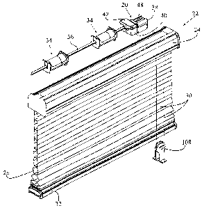
Figures 1 through 4 show a first embodiment of a worm gear lift drive 20 made
in
accordance with the present invention. Referring to Figure 1, the blind 22
includes a
head rail 24, and a dual pleated fabric 26 is suspended from the head rail 24
via lift
cables (not shown), which run downwardly inside the pleated fabric 26. As is
explained
in U.S. Patent 6,536,503, which is hereby incorporated herein by reference, a
lift cable
(not shown) is attached to each of the lift stations 34. The lift cables
extend through the
head rail 24 and through the dual pleated fabric 26 and are fastened at the
bottom of
the bottom slat (or bottom rail) 32.
Inside the head rail 24 are the worm gear drive lift mechanism 20, two lift
modules 34, and a lift rod 36, which interconnects the worm gear lift drive 20
with the lift
modules 34. This worm gear lift drive 20 is driven by two lift cord segments
30, which,
in this case, are part of one continuous loop cord. Pulling on one of the lift
cord
segments 30 causes the lift rod 36 to rotate about its longitudinal axis in
one direction,
4
CA 02558707 2006-08-30
and pulling on the other lift cord segment 30 causes the lift rod 36 to rotate
in the
opposite direction, which, in turn, causes rotation of the lift modules 34. As
the lift
modules 34 rotate first in one direction and then in the other, they cause the
lift cables
to wind up onto and unwind from the lift stations 34, thereby raising and
lowering the
covering 26, depending upon the direction of rotation.
Referring now to Figures 2-4, the lift drive 20 includes a cord pulley housing
38,
a main housing 40, a housing cover 42, a driver worm 44, a driven worm 46, and
a lift
cord pulley 48. The worm gear lift drive 20 also includes lift cord segments
30 (shown
in Figure 2).
o The driver worm 44 includes a first bearing support axle 50, a geared
portion 52,
a second bearing support 54, a non-circular cross-section portion 56, and a
third
bearing support 58. The geared portion 52 in this embodiment includes a worm
gear
62 which has a small lead angle, preferably in the 3 to 7 degree range, and
most
preferably in the 4 to 6 degree range.
The driven worm 46 includes a first bearing support axle 64, a geared portion
66,
and a second bearing support 68. The geared portion 66 in this embodiment
includes a
gear 70 which also has a small lead angle, preferably in the 3 to 7 degree
range, and
most preferably in the 4 to 6 degree range. The gear 70 of the driven worm 46
has a
larger lead angle than the lead angle of the worm 62 of the driver worm 44.
Preferably,
2o this driven worm lead angle is only slightly larger than the driver worm
lead angle, larger
by 5 degrees or less, and preferably larger by 1 to 3 degrees.
In the embodiment shown here, the lead angle of the driven worm 46 is
approximately one degree larger than the lead angle of the driver worm 44 (the
difference between the two lead angles is approximately one degree). Since the
threads on the driver 44 and driven 46 worms must mesh for the worm gear drive
lifter
20 to operate, the axis of rotation of one of the worms is offset from the
axis of rotation
of the other worm by the difference between the two lead angles (which, as
indicated
5
CA 02558707 2006-08-30
above, is about one degree in this embodiment). This condition is depicted in
more
detail in the figures for the embodiment for a titter mechanism below, such as
in Figure
11, in which the axis of rotation 174 of the driven worm 146 is sloped down
one degree
from the axis of rotation 172 of the driver worm 144.
The driven worm 46 defines an inner shaft 75 with a non-circular hollow cross-
section. This hollow shaft 75 engages the similarly-profiled lift rod 36 as
described in
more detail below. The two non-circular profiles mate, so the lift rod 36 and
the driven
worm 46 rotate together, with the axes of rotation of the driven worm 46 and
of the lift
rod 36 being the same.
The main housing 40 includes side walls 76, 78 and end walls 80, 82. Each of
the end walls 80, 82 defines two "U"-shaped saddles. The end wall 80 defines
the
saddles 84a, 86a, and the end wall 82 defines the saddles 84b, 86b. The
saddles 84a,
84b rotationally support the bearing supports 68, 64 of the driven worm 46 and
properly
align the driven worm 46 relative to the driver worm 44. The saddles 86a, 86b
rotationally support the bearing supports 54, 50of the driver worm 44 and
properly align
the driver worm 44 relative to the driven worm 46.
When the driver and driven worms 44, 46 are assembled in the main housing 40,
the location of the support saddle structures 84a, 84b and 86a, 86b for the
worms 46,
44, respectively, automatically align the axes of rotation of the worms 44, 46
such that
2o these axes are offset from being truly parallel to each other by the
difference in the lead
angles of the worms 44, 46, which, in this particular embodiment, is one
degree.
The main housing 40 also includes a rectangular portion 88 appended to the end
wall 80, and this rectangular portion 88 houses the lift cord pulley 48 and
provides a
slotted opening 90 through which the lift cords 30 exit the lift drive
mechanism 20. The
25 cord pulley housing 38 fits over this rectangular portion 88, which also
includes a
through opening 92 which provides rotational support for the bearing surface
58 of the
driver worm 44. Finally, this rectangular portion 88 also includes a radiused
surface 89
6
CA 02558707 2006-08-30
to gently guide one of the lift cords 30 under and around the lift cord pulley
48 as
explained in more detail below.
Referring to Figure 3, the housing cover 42 defines arcuate recesses 94a, 94b,
which, when the cover 42 is assembled onto the housing 40, lie adjacent the
end wall
80 of the housing 40 above the arcuate recesses 84a, 86a. The housing cover 42
also
defines identical arcuate recesses on its other end wall, which, when the
cover 42 is
assembled onto the housing 40, lie adjacent the other end wall 82 of the
housing 40
above the arcuate recesses 84b, 86b. These arcuate recesses in the housing
cover 42
cover the respective shaft supports 50, 54, 64, 68 and act to hold the driver
drum 44
and the driven drum 46 securely in place inside the main housing 40 when the
housing
cover 42 is assembled to the main housing 40.
The main housing 40 includes several projections 98 (See Figure 3) which
cooperate with matching holes 100 in the housing cover 42 and in the cord
pulley
housing 38 to assemble all the parts 38, 40, 42 together using the snap-
together design
for component assembly disclosed in U. S. Patent application S/N 60-679956
filed on
May 5, 2005, which is hereby incorporated herein by reference.
The cord pulley housing 38 also includes a ledge 99 which extends over the
housing cover 42 when the worm gear lift drive 20 is fully assembled. This
ledge 99,
(together with the projection 98' in the housing cover 42 which engages the
matching
2o hole 100' in the cord pulley housing 38) helps ensure that the housing
cover 42 remains
firmly assembled to the main housing 40 and improves the assembled integrity
of the
worm gear lift drive 20.
Finally, the lift cord pulley 48 is a substantially cylindrical element with
flanges
102 at its ends. The lift cord pulley 48 defines a non-circular cross-section
hollow, inner
shaft 104 sized to receive the non-circular cross-section portion 56 of the
driver worm
44, as described in more detail below. It may be noted that the substantially
cylindrical
surface 106 of the lift cord pulley 48 may have a polygonal cross-sectional
profile
7
CA 02558707 2006-08-30
(instead of a circular cross-sectional profile). In Figure 3, the surface 106
is depicted as
having an octagonal cross-sectional profile, but other polygonal cross-
sectional profiles
may be used as desired, as well as a circular or other cross-sectional
profile. A
polygonal cross-sectional profile may enhance the "grip" of the lift cord 30
on the pulley
48. Of course, other ways for improving the grip of the lift cords 30 (such as
knurling, or
placing a rubber sleeve on the surface 106) may be used as well.
Lift Drive Assembly
To assemble the lift drive 20, the lift cord pulley 48 is slid over the end of
the
o driver worm 44 such that the non-cylindrically profiled portion 56 of the
driver worm 44
engages the hollow shaft 104 of the pulley 48. This assembly is installed in
the main
housing 40 with the bearing support surfaces 50, 54 of the driver worm 44
resting on
the saddles 86b, 86a of the main housing 40, and the pulley 48 lying within
the
rectangular portion 88 of the main housing 40. Similarly, the driven worm 46
is also
installed in the main housing 40 with the bearing support surfaces 64, 68 of
the driven
worm 46 resting on the saddles 84b, 84a of the main housing 40.
As indicated earlier, the support saddles 84a, 84b and 86a, 86b on the main
housing 40 are located to ensure that the axes of rotation of the driver and
driven
worms 44, 46 are offset from each other by the difference in the lead angles
of the
2o threads of the driver and driven worms 44, 46. In the embodiment depicted
here, this
offset is approximately one degree.
The lift cord segments 30 (which in this embodiment are part of a single lift
cord
wrapped in a continuous loop) are fed through the slotted opening 90 of the
rectangular
portion 88 of the main housing 40 and wrapped several times around the pulley
48 (in
25 the embodiment depicted in Figure 2, the lift cord 30 is wrapped three
times around the
pulley 48). The lift cord segments 30 are then fed back out of the main
housing 40 via
the same slotted opening 90 and routed down and around a tension pulley 108.
The
CA 02558707 2006-08-30
tension on the lift cord 30 is adjusted so that pulling on one side of the
lift cord loop 30
results in rotation of the cord pulley 48 (and consequent raising or lowering
of the blind
22 as discussed below) with little, if any slippage of the lift cord 30 on the
pulley 48.
It may be noted that the particular embodiment of the worm gear lift drive 20
of
Figure 2 is designed to operate with both lift cord segments 30 under tension,
which
may be accomplished by having the lift cord 30 be a continuous loop tied down
around
the tension pulley 108. If the tension on the lift cord 30 is not maintained,
the lift cord
30 slips around the drive pulley 48 and the lift drive 20 fails to operate.
The housing cover 42 is then installed over the main housing 40, and the
pulley
o housing 38 is installed over the pulley 48, with the bearing support surface
58 of the
driver worm 44 resting in the opening 92 of the pulley housing 38. The
projections 98,
98' engage with the holes 100, 100', respectively, to lock together the
housings 38, 40
and the housing cover 42.
The lift rod 36 is then inserted through the hollow shaft 75 of the driven
worm 46,
and the entire assembly is then installed in the head rail 24, mating the lift
rod 36 with
the lift stations 34 and snapping the outer contour of the housing into the
inner contour
of the head rail so the housing is fixed relative to the head rail. (See Fig.
1 )
Operation
2o Once the worm gear lift drive 20 is installed in the head rail 24 as
described
above and as shown in Figure 1, it is ready for operation. Pulling on one of
the lift cord
segments 30 causes the cord pulley 48 to rotate in one direction. As an
example, we
can assume that, as the operator pulls on a first lift cord segment 30, the
cord pulley 48
rotates in a clockwise direction (as seen from the left end of the window
covering) and
25 the first lift cord segment 30 unwinds from one side of the cord pulley 48.
At the same
time, the second lift cord segment 30 winds up onto the cord pulley 48 (this
second lift
cord segment 30 is guided by the generously radiused surface 89 of the
rectangular
9
CA 02558707 2006-08-30
portion 88 of the main housing 40, to the far side of the pulley 48).
This clockwise rotation of the cord pulley 48 drives the driver worm 44 in a
clockwise direction (as the non-cylindrically profiled shaft 56 of the driver
worm 44
engages the similarly non-cylindrically profiled hollow shaft 104 of the cord
pulley 48).
The driver worm 44, in turn, drives the driven worm 46 in a counter-clockwise
direction
(as the threaded gear portion 52 of the driver worm 44 meshes with the
threaded gear
portion 66 of the driven worm 46). The counter-clockwise rotation of the
driven worm
46 causes the counter-clockwise rotation of the lift rod 36 (as the non-
cylindrically
profiled shaft hollow shaft 75 of the driven worm 46 engages the similarly non-
1o cylindrically profiled lift rod 36). The rotation of the lift rod 36 causes
the rotation of the
lift modules 34, pulling up on the lift cables which run inside the double
pleated fabric
26 in order to lift the bottom rail 32 of the window covering 22.
When the blind is lifted to the desired position, the operator releases the
lift cord
segment 30, and the blind 22 remains in that position. Should something
attempt to
15 reposition the blind 22 (for instance, a person physically pulling down on
the bottom rail
32, or the force of gravity acting on the blind 22), the worm gear lift drive
20 locks up,
since the driven worm 46 is unable to back drive the driver worm 44 without
locking up
the lift mechanism 20.
If the operator pulls down on the second lift cord segment 30, the entire
2o sequence described above repeats itself, but in the opposite direction. As
this second
lift cord segment 30 unwraps from the cord pulley 48 (and the first lift cord
segment 30
wraps back onto the cord pulley 48), the cord pulley 48 rotates in a counter-
clockwise
direction, as does the driver worm 44. The driven worm 46 then rotates in a
clockwise
direction as does the lift rod 36, turning the lift modules 34 so as to lower
the lift cables
25 which run inside the double pleated fabric 26 in order to lower the bottom
rail 32 of the
window covering 22. Once again, releasing the lift cord segment 30 at any
position
freezes the blind 22 in that position.
CA 02558707 2006-08-30
While this embodiment uses a cord drive to drive the driver worm gear, it
would
also be possible to use other known types of drives, such as an electric
motor, a hand
crank, or other known drives which are commonly used for raising and lowering
window
shades. Also, while this worm gear lift drive 20 has been described above as
used to
drive a lift rod 36 which drives lift stations 34, it could alternatively be
used to drive a tilt
rod which drives tilt stations, as described below, or to open and close a
vertical blind or
a garage door, or to drive other aspects of coverings.
Tilt Drive Mechanism
o Figures 5 through 18 show another embodiment of a worm gear tilt drive 120
made in accordance with the present invention. Referring to Figure 5, the
blind 122
includes a head rail 124 and a plurality of slats 126 suspended from the head
rail 124
by means of tilt cables 128 and the associated cross cords which together
comprise
ladder tapes. As is typical in a window blind, two lift cords 130 extend
through the head
rail 124 and through holes (not shown) in the slats 126 and are fastened at
the bottom
of the bottom slat (or bottom rail) 132, which typically is heavier than the
other slats
126. Inside the head rail 124 are a conventional cord lock mechanism 119, a
cord titter
module including the worm gear tilt drive 120, two tilt modules 134, and a
tilt rod 136,
which interconnects the worm gear drive 120 with the tilt modules 134. This
worm gear
2o tilt drive 120 is driven by tilt cord segments 138. Pulling on one of the
tilt cord segments
138 causes the tilt rod 136 to rotate around its longitudinal axis which, in
turn, causes
the tilt modules 134 to rotate as well. This action lifts up on one side of
the tilt cables
128 while lowering the other side, in order to rotate the slats 126 to the
open or closed
position.
25 Referring now to Figures 6 through 10, the worm gear tilt drive 120
includes a
front housing 140, a rear housing 142, a driver worm 144, a driven worm 146,
and a
cord titter pulley 148. The worm gear drive 120 also includes tilt cord
segments 138
11
CA 02558707 2006-08-30
(not shown in these views but seen in Figure 5, together with the tilt rod
136).
Referring to Figures 12 and 13, the driver worm 144 includes a first bearing
support axle 150, a geared portion 152, a second bearing support 154, and a
non-
cylindrically profiled, cantilevered portion 156, terminating with a short
radial indentation
158 and a tapered end 160. The geared portion 152 in this embodiment includes
a
worm gear 162 with a single gear start (as shown in Figure 13), and this gear
162 has a
small lead angle, preferably in the 3 to 7 degree range, and most preferably
in the 4 to
6 degree range.
Referring to Figures 14 and 15, the driven worm 146 includes a first bearing
1o support axle 164, a geared portion 166, and a second bearing support 168.
The
geared portion 166 in this embodiment includes a worm gear 170 with five gear
starts
(as shown in Figure 15), and this gear 170 has a small lead angle, also
preferably in the
3 to 7 degree range, and most preferably in the 4 to 6 degree range. The gear
170 of
the driven worm 146 has a larger lead angle than the lead angle of the gear
162 of the
15 driver worm 144. Preferably this driven worm lead angle is only slightly
larger than the
driver worm lead angle, larger by 5 degrees or less, and preferably larger by
1 to 3
degrees.
In the embodiment shown here, the lead angle of the driven worm 146 is
approximately one degree larger than the lead angle of the driver worm 144
(the
2o difference between the two lead angles is approximately one degree). Since
the
threads on the driver 144 and driven 146 worms must mesh for the worm gear
titter
drive 120 to operate, the axis of rotation of one of the two worms is offset
from the axis
of rotation of the other by the difference between the two lead angles (which,
as
indicated above, is about one degree in this embodiment). This condition is
depicted in
25 Figure 11, in which the axis of rotation 174 of the driven worm 146 is
sloped down one
degree from the axis of rotation 172 of the driver worm 144.
Referring back to Figure 15, the driven worm 146 defines an inner shaft 175
with
12
CA 02558707 2006-08-30
a non-cylindrical, hollow profile. This shaft 175 engages the similarly-
profiled tilt rod
136 as described in more detail below, so the driven worm 146 and the tilt rod
136
rotate together and have the same axis of rotation.
Referring to Figures 10 and 18, the rear housing 142 defines a large
cylindrical
cavity 176 to house the driven worm 146, and a smaller cylindrical cavity 178
to house
the driver worm 144. Referring to Figure 18, the rear wall 180 of the rear
housing 142
defines a cavity 182 for rotationally supporting the axle 150 of the driver
worm 144, as
well as a through opening 184 for rotationally supporting the axle 164 of the
driven
worm 146. The rear wall 185 of the front housing 140 defines a first through
opening
186 for rotationally supporting the axle 168 of the driven worm 146, as well
as a second
through opening 188 for rotationally supporting the axle 154 of the driver
worm 144.
The front wall 187 of the rear housing 142 includes two projections 190 (See
Figure 10) which cooperate with matching holes 192 in the front housing 140 to
assemble the front and rear housings 140, 142 using the snap-together design
for
component assembly disclosed in the U. S. Patent application S/N 60-679956
filed on
May 5, 2005, which is hereby incorporated herein by reference. A hole 194 on a
flange
196 of the front wall 187 of the rear housing 142 may also be used to further
securely
fasten the front and rear housings 140, 142 via a screw (not shown).
When the driver and driven worms 144, 146 are assembled in the front and rear
2o housings 140, 142, the location of the bearing support structures (182 and
184 in the
rear housing 142, and 186 and 188 in the front housing 140) for the worms 144,
146
automatically align the axes of rotation 172, 174 of the worms 144, 146,
respectively,
such that these axes are offset from being truly parallel to each other by the
difference
in the lead angles of the worms 144, 146, which, in this particular
embodiment, is one
degree.
Referring to Figures 10, 17, and 18, the front housing 140 defines a large,
semi-
cylindrical cavity 198 which houses the cord pulley 148. The bottom wall 200
of the
13
CA 02558707 2006-08-30
front housing 140 defines two through openings 202, 204 through which the two
tilt cord
ends 138 are threaded to be attached to the cord pulley 148 as described in
more detail
below.
Referring to Figures 10 and 18, the cord pulley 148 is a substantially
cylindrical
element with a non-cylindrically profiled, hollow inner shaft 206 sized to
receive the
mating non-cylindrically profiled, cantilevered portion 156 of the driver worm
144. A
detent projection 208 on the cord pulley 148 is deflected outwardly by the
tapered end
160 of the driver worm 144 during assembly. The detent projection 208 then
snaps
back into position into the indentation 158 of the driver worm 144, locking
the cord
1o pulley 148 against axial motion relative to the driver worm 144. Thus, the
cord pulley
148 is releasably mounted onto the cantilevered portion 156 of the driver worm
144,
and, when the cord pulley 148 rotates, it rotates the driver worm 144 as well.
The cord pulley 148 defines annular flanges 210, 212 at its ends, as well as a
third annular flange 214 approximately half-way between the end flanges 210,
212.
15 Two through openings 216, 218 extend through the cylindrical wall of the
cord pulley
148 and into the inner core 220 (See Figure 18) so that the tilt cord segments
138 may
be secured to the cord pulley 148 as described below.
Tilter Assembly
2o To assemble the worm gear tilt drive 120, the driver worm 144 is matched
against the driven worm 146 such that their corresponding geared portions 152,
166 are
meshed. The rear housing 142 is installed such that the driven worm 146 is
inside the
larger cavity 176, and the driver worm 144 is inside the smaller cavity 178.
The bearing
support axle 150 of the driver worm 144 rests in the cavity 182, and the
bearing support
25 axle 164 of the driven worm 146 rests in the through opening 184.
The front housing 140 is brought up against the front wall 187 of the rear
housing
142, such that the projections 190 line up with the holes 192, and the
assembly snaps
14
CA 02558707 2006-08-30
together. The bearing support (or axle) 168 of the driven worm 146 rests on
the
through opening 186 on the front housing 140, and the bearing support (or
axle) 154 of
the driver worm 144 rests on the through opening 188 on the front housing 140.
As
indicated earlier, the openings 186, 188 on the front housing 140 are located
to ensure
that the axes of rotation 172, 174 of the driver and driven worms 144, 146 are
offset
from each other by the difference in the lead angles of the threads of the
driver and
driven worms 144, 146. In the embodiment depicted, this offset is
approximately one
degree.
The tilt cord segments 138 are brought up through the head rail 124 (See
Figure
5). One tilt cord segment 138 is fed through one of the openings 202 in the
front
housing 140, and is then fed through one of the openings 216 in the cord
pulley 148
where it is secured to the cord pulley 148 (for instance, by tying a knot or
other
enlargement to the end of the tilt cord 138 so that the end can not be pulled
back out
through the opening 216). The other tilt cord segment 138 is likewise fed
through the
other opening 202 in the front housing 140, is fed through the other opening
218 in the
cord pulley 148, and is secured with an enlargement such as a knot. One of the
tilt
cord segments 138 is then partially wrapped around the cord pulley 148, while
the other
tilt cord segment 138 may remain unwrapped or, if desired, may be counter-
wrapped
(wrapped in the opposite direction) onto the cord pulley 148. These two
sections of
2o wrapped, counter-wrapped tilt cord segments 138 are separated by the middle
annular
flange 214 to keep the cord segments 138 from wrapping over each other.
The cord pulley 148 is then inserted into the cavity 198 of the front housing
140
such that the cantilevered portion 156 of the driver worm 144 fits into the
hollow shaft
206 of the cord pulley 148, and the detent 208 latches into the indentation
158 of the
driver worm 144. The titter 120 is now ready for installation into the head
rail 124, with
its outer contour snap fitting into the inner contour of the head rail to fix
it relative to the
head rail, and with the tilt rod 136 fitting into the hollow shaft 175 of the
driven worm
CA 02558707 2006-08-30
146.
The tilt rod 136 also connects to the tilt modules 134 in order to drive the
tilt
modules 134, which are described in U. S. Patent No. 6,536,503, which is
incorporated
herein by reference.
Operation
Once the worm gear drive 120 is installed in the head rail 124 as described
above and as shown in Figure 5, it is ready for operation. Pulling on one of
the tilt cord
segments 138 causes the cord pulley 148 to rotate in one direction. As an
example, we
1o can assume that, as the operator pulls on a first tilt cord segment138, the
cord pulley
148 rotates in a clockwise direction (as seen from the left end of the window
covering)
as the first tilt cord segment 138 unwinds from one side of the annular flange
214 of the
cord pulley 148. At the same time, the second tilt cord segment 138 winds up
onto the
cord pulley 148 on the other side of the annular flange 214.
This clockwise rotation of the cord pulley 148 drives the driver worm 144 in a
clockwise direction (as the non-cylindrically profiled shaft 156 of the driver
worm 144
engages the similarly non-cylindrically profiled hollow shaft 206 of the cord
pulley 148).
It also drives the driven worm 146 in a counter-clockwise direction (as the
threaded
portion 152 of the driver worm 144 meshes with the threaded portion 166 of the
driven
2o worm 146). The counter-clockwise rotation of the driven worm 146 causes the
counter-
clockwise rotation of the tilt rod 136 (as the non-cylindrically profiled,
hollow shaft 175 of
the driven worm 146 engages the similarly non-cylindrically profiled tilt rod
136). The
rotation of the tilt rod 136 causes the rotation of the tilt modules 134,
pulling up on one
side of the tilt cables 128 while lowering the other side of the tilt cables
128 in order to
tilt the slats 126 of the window covering 122.
When the slats 126 are tilted to the desired position, the operator releases
his
grip on the tilt cord segment 138, and the slats 126 remain in that position.
Should
16
CA 02558707 2006-08-30
something attempt to reposition the slats 126 (for instance, a person
physically handling
the slats 126, or the force of gravity acting on the slats 126), the worm gear
drive 120
locks up, since the driven worm 146 is unable to back drive the driver worm
144 without
locking up the titter mechanism 120.
If the operator pulls down on the second tilt cord segment 138, the entire
sequence described above repeats itself, but in the opposite direction. While
this
second tilt cord segment 138 unwraps from the cord pulley 148 (and the first
tilt cord
138 wraps back onto the cord pulley 148), the cord pulley 148 rotates in a
counter-
clockwise direction, as does the driver worm 144. The driven worm 146 then
rotates in
1o a clockwise direction as does the tilt rod 136, turning the tilt modules
134 so as to tilt
the slats 126 in the opposite direction. Once again, releasing the tilt cord
segment 138
freezes the slats 126 in the desired position.
Additional Embodiment of a Worm Gear Tilt Drive Mechanism
15 Figures 19 and 20 depict another worm gear tilt drive mechanism 120' made
in
accordance with the present invention. A comparison of Figure 19 with Figure
10
shows that the main difference is in the shape of the tilt cord pulley 148',
which in this
embodiment has the shape of two frustroconical elements placed end-to-end,
resulting
in an hourglass-shaped pulley 148'. In addition, the surface 222' of the
pulley 148' is
2o now a threaded surface to help guide the placement of the tilt cord
segments 138 onto
the surface 222'.
As is known in the industry, the tilting of slats 126 in a blind 122 requires
a
relatively constant force throughout the entire range of motion of the slats
126 except at
the end of the stroke, when tilting the slats 126 of the blind 122 to the
fully closed
25 position (either room-side up or room-side down). At that point, the force
required to
fully close the blind 122 increases substantially, as the entire set of slats
126 and the
bottom rail 132 are lifted by the tilt mechanism in order to achieve total
closure of the
17
CA 02558707 2006-08-30
blind 122.
The worm gear tilt drive mechanism 120' addresses this issue by the hourglass
shape of the tilt cord pulley 148'. When the slats 126 of the blind 122 are
fully closed in
one direction (say room-side up), a first tilt cord segment 138 begins
unwinding from the
tilt cord pulley 148' starting at the smallest diameter of the tilt cord
pulley 148'. The
second tilt cord segment 138 is fully (or substantially) unwound from the tilt
cord pulley
148' and hanging down off of its largest diameter, as it starts winding onto
the tilt cord
pulley 148', moving toward the center of the tilt cord pulley 148' where it
has the
smallest diameter.
1o As the blind 122 continues to tilt open, and then goes on to tilt closed in
the
opposite direction (room-side down), the first tilt cord segment 138 advances
on the
threaded surface 222' of the tilt cord pulley 148', unwinding itself toward
the largest
diameter, which results in progressively larger torque, until the highest
torque is
obtained at the end of the travel of the first tilt cord segment, where it is
most needed to
counter the extra force required to raise the slats 126 and bottom rail 132 to
ensure
complete closure of the blind 122. At that same time, the second tilt cord
segment 138
is fully (or substantially) wound up onto the threaded surface 222' of the
tilt cord pulley
148' .
To put it another way, the largest torque is obtained when the tilt cord
segment
138 is unwinding from the largest diameter of the tilt cord pulley 148' but
does so at the
expense of longer linear travel of the tilt cord segment 138 for a
corresponding angular
displacement of the slats 126. However, as the tilt cord segment 138 moves
down
along the frustroconical surface 222' toward the smaller diameter of the tilt
cord pulley
148', the torque is reduced, but less of a linear travel of the tilt cord 138
is required for a
corresponding angular displacement of the slats 126. Thus, the frustroconical
tilt cord
pulley 148' allows for the tilt cord pull in the center of the tilt range of
the blind 122
(where the diameter of the tilt cord pulley 148' is smallest) to be minimized
so that the
18
CA 02558707 2006-08-30
total tilt cord travel is greatly reduced without increasing the maximum
operational force
of the titter 120'.
The actual location of the tilt cord segments 138 on the tilt cord pulley 148'
may
be chosen either to minimize total distance traveled by the tilt cord segments
138 or to
maximize the torque available to tilt the blind closed in one or the other
directions
(room-side up or room-side down) or both, or to achieve any desired
combination
thereof (of distance traveled versus torque available). Also, in order to
minimize the
length of the tilt cord pulley 148', the tilt cord segments 138 could be
wrapped such that
the first tilt cord segment 138 is fully wound onto the threaded surface 222'
of the tilt
1o cord pulley 148', while the second tilt cord segment 138 is fully unwound
from the tilt
cord pulley 148' and is on the same end of the tilt cord pulley 148' as the
first tilt cord.
Thus, as the first tilt cord unwinds from the tilt cord pulley 148', the
second tilt cord
winds up on the same thread just being vacated by the first tilt cord. As a
result, the tilt
cord pulley 148' only needs to have one half the total number of threads as
may
otherwise be required, resulting in a shorter tilt cord pulley 148'.
While this is not shown in the figures of this specification, it may well be
possible
to replace the lift cord pulley 48 (See Figure 3) of the worm gear lift drive
mechanism 20
discussed earlier with a frustroconical, threaded pulley similar to the pulley
148' of the
worm gear drive tilt mechanism 120' disclosed above. In this instance, a
simple
2o frustroconical threaded pulley, or perhaps a combined part-frustroconical,
part-
cylindrical pulley, instead of the double frustroconical threaded pulley 148'
may be all
that is needed as discussed below.
In a typical blind, a progressively larger force is required to lift (or
raise) the blind.
When the blind is in the fully lowered position, the ladder tapes (the tilt
cables) are
supporting all the slats and only the bottom rail needs to be raised at the
onset. As the
raising of the blind progresses, more of the slats stack up onto the bottom
rail, and this
additional weight must be countered with a larger force. In essence, the lift
cords and
19
CA 02558707 2006-08-30
the ladder tapes exchange loads as the blind is raised and lowered. As this
load shifts
from the ladder tapes to the lift cords when raising the blind, a larger force
is required to
raise the blind.
The use of a frustroconical pulley with a threaded surface instead of the
cylindrical pulley 48 of the worm gear drive lift mechanism 20 in Figure 3
would reduce
the amount of input force required by the operator pulling down on the lift
cord segment
30 (at the expense of more distance traveled by the lift cord segment 30). If
the pulley
had a first portion which was cylindrical and a second portion which was
frustroconical
with an increasing diameter as you move away from the cylindrical portion, the
lift cord
o segment 30 could begin unwinding from the cylindrical portion of the pulley
as it begins
raising the blind. The force required to continue raising the blind would
continue to
increase steadily until it reached a higher acceptable limit (say, for
instance, 12 to 15
pounds of force by the operator). At that point, the lift cord segment would
start to
unwind from the frustroconical portion of the pulley (at an increasingly large
diameter)
15 which would act to reduce the amount of force required, countering the
increasing
amount of force to continue raising the blind. The force required by the
operator could
be kept at or below the threshold limit deemed acceptable by the operator.
Since the lift cord pulley is practically parallel to the longitudinal axis of
the head
rail (in the embodiments shown, the axis of rotation of the lift cord pulley
is only offset
20 one (1 ) degree from the axis of rotation of the driven worm 46, which is
most likely
aligned with the longitudinal axis of the head rail 24), it is possible to
have a fairly long
lift cord pulley within the confines of the head rail in order to accommodate
a long
stroke of the lift cord segment 30.
Of course, it may be desirable to keep the continuous loop feature of the lift
cord
25 segments 30 of Figure 1 for the lift drive instead of the two separate tilt
cord segments
138 of Figure 5. This could still be accomplished despite the use of a
frustroconical
threaded pulley, or a combined part-frustroconical, part-cylindrical pulley as
described
CA 02558707 2006-08-30
above. Means for maintaining a proper tension on the continuous loop lift cord
segments 30 (such as the use of biasing spring to pull on the tension pulley
108) may
be used for the operation of such a lift drive.
Figure 21 depicts yet another embodiment of a worm gear tilt drive 120" made
in
accordance with the present invention. A comparison of Figure 21 with Figure
18
shows that the main difference is in the shape of the driver worm 144", which
in this
embodiment has an interrupted thread portion 230" (which can be readily
appreciated in
Figure 22). In addition, the housing 142" has a bearing support portion 232"
which
extends toward, and receives, the interrupted thread portion 230" of the
driver worm
144" to provide additional rotational support to the driver worm 144". This
support is
provided approximately at the midpoint of the geared portion 152" of the
driver worm
144", resulting in a geometrically increased shaft strength to obtain much
greater
torsional output. Other than this, there is no difference in the operation and
performance of this worm gear tilt drive 120" relative to the worm gear tilt
drive 120
described above.
While these embodiments use a cord drive to drive the driver worm gear, it
would
also be possible to use other known types of drives, such as an electric motor
which is
often used in lift drives, or a tilt wand, which is commonly used for tilting
window
shades. Also, although it is not shown in the drawings herein, it would be
possible to
2o use worm gear drives both for raising the blind and for tilting the slats
in the same blind.
While some specific lead angles and gear ratios have been taught here, it is
understood
that other embodiments may use different lead angles and/or gear ratios.
The embodiments of the invention described above are a few examples of
products made in accordance with the present invention. It will be obvious to
those
skilled in the art that modifications may be made to the embodiments described
above
without departing from the scope of the present invention.
21