Note : Les descriptions sont présentées dans la langue officielle dans laquelle elles ont été soumises.
CA 02558948 2006-09-08
GRDSP0374CAA
WATER-PURIFICATION DEVICE
FOR A POTABLE WATER SYSTEM
FIELD OF THE INVENTION
This invention relates generally to a water-purification device for a potable
water system.
BACKGROUND OF THE INVENTION
A potable water system can be installed, for example, in an aircraft to
supply cabin outlet facilities (e.g., handwash basins in lavatories and sinks
in
onboard kitchens) with fresh water. A potable water system can comprise a
water storage tank, a supply line and tap lines which connect the water supply
tank to the outlet facilities. The supply line will often include a device
which
io emits ultraviolet light into the water for purification purposes. If the
potable water
system is installed in an aircraft, the water-purification device receives
operational power from an onboard source.
SUMMARY OF THE INVENTION
The present invention provides a lightweight and/or low-power ultraviolet
device which purifies water in a potable water system. In this water-
purification
device, light emitting diodes produce ultraviolet light and a driver circuit
powers
the light emitting diodes. With specific reference to aircraft applications,
the
diodes are lightweight components when compared to, for example, the gas
discharge lamps (with large heavy ballasts) conventionally used for
purification
purposes in potable water systems. In any event, the lightweight and/or low-
power advantages of the water-purification device are achieved without
compromising effectiveness and/or efficiency.
More particularly, the present invention provides a water-purification
device comprising a chamber through which water flows, at least one light-
emitting diode that radiates ultraviolet light into the water within the
chamber,
and a driver circuit for providing power to the light-emitting diode(s).
Preferably,
1
CA 02558948 2006-09-08
a plurality of light-emitting diodes are electrically connected in series by
conductors. The drive circuit includes a controller which controls output of
power to the light-emitting diodes via appropriate circuitry. The water-
purification
device and/or the drive circuit can include a feedback accessory (providing
information regarding emission and/or purification), an input accessory
(allowing
the input of optional and/or required commands) and/or a fault-status
accessory.
These and other features of the invention are fully described and
particularly pointed out in the claims. The following descriptive annexed
drawings set forth in detail a certain illustrative embodiment of the
invention, this
io embodiment being indicative of but one of the various ways in which the
principles of the invention may be employed.
DRAWINGS
Figure 1 is a schematic illustration of a potable water system including an
ultraviolet water-purification device according to the present invention.
1s Figures 2A - 2C are schematic illustrations of the ultraviolet water-
purification device with different arrangements of the light emitting diodes
and/or
the conductors therebetween.
Figure 3 is a schematic illustration of the driver circuit.
DETAILED DESCRIPTION
20 Referring now to the drawings, and initially to Figure 1, a potable water
system 10 according to the present invention is schematically shown. The
potable water system 10 can comprises a water tank 12, a pump 14, and outlet
facilities 16. In the illustrated system 10, the pump 14 conveys water from
the
tank 12 through a supply line 18 (e.g., pipes, tubes or other hydraulic
conduits)
25 from which water can be tapped at the outlet facilities 16. Untapped water
can
be directed to another device (e.g., a coffee maker) and/or drain.
The potable water system 10 can also include other components such as,
for example, another tank, another pump, a filtering device, tank-filling
means,
and/or flow-directing valves. Additionally or alternatively, a potable water
30 system without a tank 12 and/or a pump 14 is possible with, and
contemplated
2
CA 02558948 2006-09-08
by, the present invention. For example, other sources of pressurization (e.g.,
bleed air) could be employed. If is further noted that the potable water
system
could instead be a recirculating system wherein untapped water is returned to
the storage tank.
5 The potable water system 10 further comprises a water-purification
device 22 according to the present invention. In the illustrated embodiment,
the
system 10 has one device 22 is positioned in the supply line 18. The water-
purification device 22 could be positioned elsewhere in the system and/or
additional devices 22 could be provided in the supply line 18 or in any other
io suitable location in the system 10. The device location(s) within the
system 10
will typically be selected to optimize its purification purposes while also
being
compatible with installation, inspection and maintenance. Typically, a filter
is
positioned upstream of the water-purification device 22 for removal of non-
organic particles.
1s The potable water system 10 of the present invention can be designed
specifically for use on a vehicle, and more specifically for use on aircraft.
In an
aircraft application, the outlet facilities 16 can comprise, for example,
cabin
facilities such as wash basins in lavatories and/or sinks in onboard kitchens.
In
any event, lightweight and/or low-power-consumption components (with no
sacrifice on effectiveness and/or efficiency) are usually welcomed in aircraft
potable water systems.
Referring now to Figures 2A-2C, the water-purification device 22 is
schematically shown in more detail. The device 22 includes a purification
chamber 23 which, as discussed above, can be part of the supply line 18 of the
potable water system 10. The chamber 23 shown in Figure 2C is defined by
wall structure having at least a portion which allows for transmission of
ultraviolet
light. For example, an entire cylindrical wall defining the chamber 23 can be
made of an UV-transmissive material or a cylindrical wall defining the chamber
23 can have a UV-transmissive window. The chamber 23 shown in Figure 2A
3o and the chamber 23 shown in Figure 2B need not allow for the transmission
of
ultraviolet light.
3
CA 02558948 2006-09-08
The water-purification device 22 also includes at least one light-emitting
diode 24. A light-emitting diode (LED) is a semiconductor that emits
incoherent
narrow-spectrum light when electrically biased in the forward direction. The
light-emitting diode(s) 24 of the present invention can be light emitting
diodes of
all types, such as light emitting polymers, semiconductor dies that produce
light
in response to current, organic light-emitting diodes, electro-luminescent
strips,
and other such systems. The light-emitting diode(s) 24 may be packaged, non-
packaged, surface mount, chip on board, and/or other configurations. The light-
emitting diodes 24 can also be associated with a material (e.g., a phosphor)
io which converts emitted energy to a different wavelength.
Preferably, the water-purification device 22 includes a plurality of light-
emitting diodes 24. For example, the device 22 in the drawings includes five
light-emitting diodes 24 for the sake of ease in illustration, and a diode-
number
within this range (e.g., two to ten) might be sufficient in some situations.
is However, in some situations (e.g., high water volume, fast flow rate,
elevated
contamination risk, etc.), several more diodes 24 (e.g., ten to thirty, fifty,
a
hundred, and/or more) may be necessary and/or desired. In any event, the
plurality of light-emitting diodes 24 can be of the same or different designs,
depending upon the needs of a particular potable water system.
20 In the present invention, the light-emitting diodes 24 produce ultraviolet
light (i.e., light in the ultraviolet spectrum and the deep blue region of the
visible
spectrum). The light preferably has radiation wavelengths between 200 nm to
400nm, and more preferably (if possible) between 245 nm and 285 nm, which is
the EPA stated optimum range for germicidal effects. Ultraviolet light from
the
25 diodes 24 can potentially kill 99% of bacteria with a 30mW-sec/cm2
exposure.
Candidate light-emitting diode materials (i.e., materials having bandgap
energy corresponding to the desired wavelength) can include, for example,
gallium nitride (GaN) and associated Group III nitride compounds such as
aluminum gallium nitride (AIGaN), indium gallium nitride (InGaN), and aluminum
30 indium gallium nitride (AlInGaN). Diodes which emit light in the 200nm to
400nm range are available on the market, from, for example, Nichia Corporation
of Tokoshima, Japan.
4
CA 02558948 2006-09-08
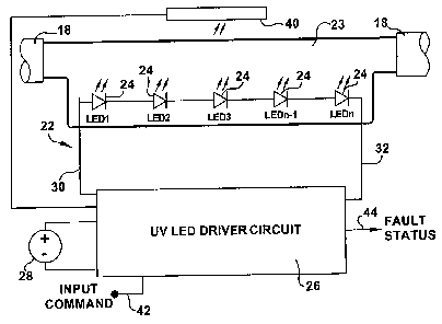
The water-purification device 22 further comprises a driver circuit 26
which receives operational power from an appropriate voltage source 28 (e.g.,
28 VDC). In an aircraft application, the voltage source 28 would be an onboard
power source. Onboard power sources are required for a number of aircraft
functions, some being crucial for flight (e.g., electric deicers) and others
(such as
the potable water system 10) being only important for comfort. It is generally
desirable to keep onboard power requirements to a minimum, especially for
functions not crucial for flight, whereby the low power requirements of the
light-
emitting diodes 24 will usually be welcomed.
The driver circuit 26 selectively applies voltage, via conductors 30 and 32,
to the light-emitting diodes 24 to cause them to emit radiation in the desired
wavelength range (i.e., 200nm to 400nm). The application of the voltage can be
applied on a periodic basis, upon detection of relatively high levels of
contamination, upon a predetermined maintenance cycle, and/or upon tapping
1s of water from the supply line 18. If the potable water system 10 is a
recirculating
system, a continuous application of voltage may be desirable to maintain water
purity without any sudden spikes in power requirements. That being said, the
water-purification device 22 may be part of a larger power cycle in which a
variety of aircraft components are powered at alternate times whereby
intermittent operation may be most plausible.
If the water-purification device 2 has a plurality of light-emitting diodes
24,
they can be connected to each other by conductors 34. The position of the
light-emitting diodes 24 relative to the chamber 23 and/or within the chamber
23
may be based on purification efficiency, construction requirements, inspection
abilities, and/or maintenance convenience. Likewise, the position of the
conductors 34 may be based on construction, inspection and maintenance
issues, as well as electrical issues, such as the risk of short-circuiting.
In Figure 2A, the light-emitting diodes 24 are positioned within the water
chamber 23 and the conductors 34 extend outside the chamber 23. In Figure
3o 2B, both the light-emitting diodes 24 and the conductors 34 are positioned
within
the water chamber 23. In these embodiments, the diodes 24 can be made to
withstand water immersion and/or they can be positioned in a protective (UV
5
CA 02558948 2006-09-08
transparent) tube within the chamber 23. With particular reference to Figure
2A, the chamber-defining wall can have ports or other means for electrically
connecting the diodes 24 to the conductors 34. With particular reference to
Figure 2B, the conductors 34 can be insulated with a waterproof material
(e.g.,
plastic) to avoid short-circuiting situations.
In Figure 2C, both the light-emitting diodes 24 and the conductors 34 are
positioned outside the transmissive chamber 23. This positioning eliminates
water-damage and/or short-circuiting concerns (and/or the need to install a
protective tube within the chamber 23). However, an outside-chamber position
io introduces the issues of proximity as emission and intensity levels will be
influenced by the distance of the diodes 24 from the water.
In the illustrated embodiment, the light-emitting diodes 24 are connected
in series as this will often be the most efficient arrangement from a power
requirement standpoint. However, the light-emitting diodes 24 could instead be
j5 connected in parallel if possible and/or practical for a certain
application,
especially if power requirements are not a critical design constraint.
Alternatively, the light-emitting diodes 24 could be individually connected to
the
driver circuit 26 (i.e., each light-emitting diode 24 having conductors 30 and
32)
for their independent operation of a specific diodes and/or group of diodes.
20 The water-purification device 22 and/or the driver circuit 26 can include a
feedback accessory 40 which provides information regarding emission and/or
purification. For example, the feedback accessory 40 can comprise a
photoreceptor or other means for sensing and/or measuring diode emittance
data within the chamber 23. Additionally or alternatively, the feedback
25 accessory 40 can comprise means for measuring water-purification levels
within
the chamber 23. In either or any case, the feedback accessory 40 would
provide the relevant data to power and/or intensity controlling components for
adjustments in diode emittance. In the illustrated embodiment, the accessory
40
receives feedback from a single region within the chamber 23, preferably by a
30 plurality of photoreceptors (or other sensors) providing independent
emission
and/or purification data. Additional feedback regions within the chamber 23,
6
CA 02558948 2006-09-08
and/or feedback regions in the supply line 18 and/or the storage tank 12 are
certainly possible with, and contemplated by, the present invention.
The water-purification device 22 and/or the driver circuit 26 can additional
include an input accessory 42 for allowing the input of optional and/or
required
s commands. Based on these commands, power and/or intensity controlling
components could activate/deactivate particular diodes, adapt power supplies,
and/or adjust intensity levels, depending upon circuit capabilities. The
optional
and/or required commands could be input during start-up, during maintenance,
and/or during flight operation of the water-purification device 22.
The water-purification system 22 and/or the drive circuit 26 can
additionally or alternatively comprise a fauit-status accessory 24. The
accessory
24 could track the operation or non-operation of crucial and non-crucial
components and provide fault-status signals or messages. For example, the
fault-status accessory 24 could indicate that certain diodes are not
functioning to
proper levels of emission and/or that other circuitry is not functioning in
their
intended manner. The fault-status signals (or messages) could be displayed on
panels observed by aircraft crew during flight and/or on portable displays
used
by maintenance crews during ground inspections. With specific reference to
maintenance applications, the accessory 24 could be used to store, track,
and/or
convey service status information.
Referring now additionally to Figure 3, the driver circuit 26 is shown in
more detail. The illustrated driver circuit 26 includes a controller 50 which
can
be, for example, a programmed microcontroller, a PID controller, a
microprocessor, or any other appropriate controlling mechanism. The controller
50 can receive input from the feedback accessory 40, can receive input from
the
command accessory 42, and/or can output signals/messages through the fault-
status accessory 44.
The power source 18 provides voltage to the controller 50 and the
controller 50 controls the output of power to the light-emitting diodes 24 via
3o appropriate circuitry. In the illustrated embodiment, C1 and C2 are storage
elements for the diode drive current, and C3 is a storage element for
controller's
power supply. Dl is a schottkey diode used for ultra-fast switching to improve
7
CA 02558948 2006-09-08
power efficiency and improve energy transfer to the light-emitting diodes 24.
D2
is a voltage reference diode and provides protection for the controller 50. R1
is
a current shunt and monitors the level of current applied to the light-
emitting
diodes 24. R2 is a voltage dropping device and regulates the amount of current
flowing into the D2 voltage reference diode. L1 is an energy storage device.
Q1
is a MOSFET transistor which switches ON and OFF and controls the amount of
current stored in the L1 device, so that when Q1 turns off, current flowing
through the L1 device is forced through the light-emitting diodes 24.
One may now appreciate that the present invention provides a water-
io purification device 22 having lightweight and/or low-power-consumption
components, with no sacrifice on effectiveness and/or efficiency. Although the
invention has been shown and described with respect to a certain preferred
embodiment, it is obvious that equivalent and obvious alterations and
modifications will occur to others skilled in the art upon the reading and
understanding of this specification. The present invention includes all such
alterations and modifications, and is limited only by the scope of the
following
claims.
8