Sélection de la langue

Search

Sommaire du brevet 2559051 

Énoncé de désistement de responsabilité concernant l'information provenant de tiers

Une partie des informations de ce site Web a été fournie par des sources externes. Le gouvernement du Canada n'assume aucune responsabilité concernant la précision, l'actualité ou la fiabilité des informations fournies par les sources externes. Les utilisateurs qui désirent employer cette information devraient consulter directement la source des informations. Le contenu fourni par les sources externes n'est pas assujetti aux exigences sur les langues officielles, la protection des renseignements personnels et l'accessibilité.

Disponibilité de l'Abrégé et des Revendications

L'apparition de différences dans le texte et l'image des Revendications et de l'Abrégé dépend du moment auquel le document est publié. Les textes des Revendications et de l'Abrégé sont affichés :

  • lorsque la demande peut être examinée par le public;
  • lorsque le brevet est émis (délivrance).
(12) Demande de brevet: (11) CA 2559051
(54) Titre français: BOUCLIER CHAUD A BORDURES SOUDEE
(54) Titre anglais: HEAT SHIELD HAVING A SEALED EDGE
Statut: Réputée abandonnée et au-delà du délai pour le rétablissement - en attente de la réponse à l’avis de communication rejetée
Données bibliographiques
(51) Classification internationale des brevets (CIB):
  • B32B 07/12 (2006.01)
  • B32B 27/04 (2006.01)
(72) Inventeurs :
  • FRYBERGER, SAMUEL B., JR. (Etats-Unis d'Amérique)
  • SELLIS, TIMOTHY D. (Etats-Unis d'Amérique)
  • BURDY, JOHN E. (Etats-Unis d'Amérique)
(73) Titulaires :
  • FEDERAL-MOGUL POWERTRAIN, INC.
(71) Demandeurs :
  • FEDERAL-MOGUL POWERTRAIN, INC. (Etats-Unis d'Amérique)
(74) Agent: GOWLING WLG (CANADA) LLP
(74) Co-agent:
(45) Délivré:
(86) Date de dépôt PCT: 2005-03-10
(87) Mise à la disponibilité du public: 2005-11-24
Licence disponible: S.O.
Cédé au domaine public: S.O.
(25) Langue des documents déposés: Anglais

Traité de coopération en matière de brevets (PCT): Oui
(86) Numéro de la demande PCT: PCT/US2005/007993
(87) Numéro de publication internationale PCT: US2005007993
(85) Entrée nationale: 2006-09-08

(30) Données de priorité de la demande:
Numéro de la demande Pays / territoire Date
60/551,682 (Etats-Unis d'Amérique) 2004-03-10

Abrégés

Abrégé français

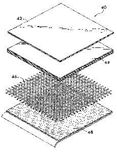
Un bouclier chaud ayant une première couche avec une surface reflétante est, une deuxième couche thermofusible, une troisième couche calorifuger et renforcée, et une quatrième couche formée de pression adhésive sensitive sont exposés. Les bordures des couches s~alignent les unes avec les autres pour former un périmètre commun à laquelle la chaleur et la pression sont appliquées pour combiner la couche de chaleur thermofusible aux autres couches et lie les couches à une autre. La couche thermofusible forme une soudure sur le périmètre ce qui évite la diffusion de fluides entre les couches.


Abrégé anglais


A heat shield is disclosed having a first layer with a reflective surface, a
second, heat fusible layer, a third insulating and reinforcing layer, and a
fourth layer formed of pressure sensitive adhesive. The edges of the layers
align with one another to form a common perimeter to which heat and pressure
are applied to fuse the heat fusible layer to the other layers and bond the
layers to one another. The heat fusible layer forms a seal on the perimeter
that prevents the diffusion of fluids between the layers.

Revendications

Note : Les revendications sont présentées dans la langue officielle dans laquelle elles ont été soumises.


7
CLAIMS
What is claimed is:
1. A heat shield comprising:
a first layer having a reflective surface and a
first edge;
a second layer comprising a heat fusible material
positioned overlying said first layer, said second layer
having a second edge substantially aligned with said first
edge; and
a third layer positioned overlying said second layer
and having a third edge substantially aligned with said first
and second edges, a portion of said second layer along said
second edge being fused to said first and third layers along
said first and third edges thereby forming a seal between said
first and third layers.
2. A heat shield according to Claim 1, wherein said
first layer comprises an aluminum foil.
3. A heat shield according to Claim 1, wherein said
second layer comprises a polymer substrate.
4. A heat shield according to Claim 2, wherein said
second layer comprises a non-woven polyester substrate.
5. A heat shield according to Claim 1, wherein said
third layer comprises a pressure sensitive adhesive substrate.
6. A heat shield according to Claim 1, further
comprising a fourth layer positioned between said first and
said third layers and having a fourth edge substantially
aligned with said first, second and third edges, a portion of

8
said fourth layer being fused to said second layer along said
fourth edge and forming said seal between said first and third
layers.
7. A heat shield according to Claim 6, wherein said
fourth layer comprises a woven glass fiber substrate.
8. A heat shield according to Claim 1, wherein said
third layer comprises an aluminum foil.
9. A heat shield according to Claim 1, wherein said
first layer comprises a metallic coating and said second layer
comprises polyethylene terephthalate, said metallic coating
being deposited on said polyethylene terephthalate.
10. A heat shield comprising:
a first layer having a reflective surface and a
first perimeter surrounding said first layer;
a second layer comprising a heat fusible material
positioned overlying said first layer, said second layer
having a second perimeter surrounding said second layer; and
a third layer positioned overlying said second layer
and having a third perimeter surrounding said third layer,
said first, second and third perimeters being substantially
aligned with one another, a portion of said second layer along
said second perimeter being fused to said first and third
layers along said first and third perimeters and thereby
forming a seal between said first and third layers.
11. A heat shield according to Claim 10, wherein said
first layer comprises an aluminum foil.
12. A heat shield according to Claim 10, wherein said
second layer comprises a polymer substrate.

9
13. A heat shield according to Claim 11, wherein said
second layer comprises a non-woven polyester substrate.
14. A heat shield according to Claim 12, wherein said
third layer comprises a pressure sensitive adhesive substrate
15. A heat shield according to Claim 10, further
comprising a fourth layer positioned between said first and
said third layers and having a fourth perimeter surrounding
said fourth layer, said fourth perimeter substantially aligned
with said first, second and third perimeters, a portion of
said fourth layer being fused to said second layer along said
fourth perimeter thereby forming said seal surrounding said
layers.
16. A heat shield according to Claim 15, wherein said
fourth layer comprises a woven glass fiber substrate.
17. A heat shield according to Claim 10, wherein said
third layer comprises an aluminum foil.
18. A heat shield comprising:
an aluminum foil layer having a first perimeter;
a glass fiber layer positioned overlying said
aluminum foil layer, said glass fiber layer having a second
perimeter;
a polyester layer positioned overlying said glass
fiber layer, said polyester layer having a third perimeter;
and
an adhesive layer positioned overlying said
polyester layer, said adhesive layer having a fourth
perimeter, said first, second, third and fourth perimeters
being substantially aligned with one another, a portion of

10
said polyester layer along said second perimeter being fused
to said aluminum foil layer, said glass fiber layer and said
adhesive layer along said first, third and fourth perimeters
and thereby forming a seal between said layers.

Description

Note : Les descriptions sont présentées dans la langue officielle dans laquelle elles ont été soumises.


CA 02559051 2006-09-08
WO 2005/110735 PCT/US2005/007993
1
HEAT SHIELD HAVING A SEALED EDGE
Field of the Invention
The invention relates to heat shields for protecting
items subjected to radiant heat sources.
Backaround of the Invention
Automotive, aeronautical and marine components positioned
in engine compartments or near heat sources such as exhaust
manifolds may be subjected to harsh thermal environments
involving high temperature radiant heat transfer. Further,
undesi red heat transfer may also occur between heat sources
such a s engines, exhaust systems and/or transmissions and the
passenger compartment of an automobile, aircraft or boat.
,.
I t is found advantageous to use insulating panels
compr i sed of a number of overlying layers to reduce heat
transfer from a heat source to other adjacent components. The
insulating layers comprising the panel may include, for
exampl e, a reflective surface such as aluminum foil, an
insults ting scrim layer of temperature resistant material such
as woven fiberglass, and a backing layer comprising a pressure
sensitive adhesive for attachment of the insulating panel to a
component or structure.
While such insulating panels are effective at reducing
radiant heat transfer, they are often inappropriate for use
where they will be subjected to contaminating fluids such as
oil, gasoline, engine coolants such as ethylene glycol,
hydraulic fluids as well as water which is encountered in
almost any environment. The fluids tend to penetrate between
the various layers through exposed edges of the panels and

CA 02559051 2006-09-08
WO 2005/110735 PCT/US2005/007993
2
accumulate with in the panels. This diminishes the insulative
effectiveness of the panels and often leads to their
accelerated corrosion and deterioration. If the fluids are
flammable, the panels can become a fire hazard as well. It
would be advantageous to provide insulating panels forming a
heat shield tha t could be used in the presence of fluids
without the aforementioned disadvantages.
Summary of the Invention
The invent ion concerns a heat shield effective at
reducing radiant heat transfer. The heat shield comprises a
first layer having a reflective surface and a first edge and a
second layer comprising a fusible material positioned
overlying the first layer. The second layer has a second edge
aligned with the first edge. The heat shield also includes a
third layer positioned overlying the second layer. The third
layer has a thi rd edge aligned with the first and second edges
of the first and second layers. A portion of the second layer
is fused to tha first and third layers along the first, second
and third edges thereby forming a seal along these edges that
prevents fluid from penetrating between the various layers.
Preferably, the first layer comprises an aluminum foil,
and the second layer comprises a non-woven polymer such as
polyester. The third layer may comprise another layer of
aluminum or could also be a pressure sensitive adhesive
substrate to allow the heat shield to be conveniently attached
to a surface or structure .
An insulating layer may be positioned between the first
and the third 1 avers. Such a layer may comprise a woven glass
fiber substrat e, glass fiber being advantageous for high
temperature applications.

CA 02559051 2006-09-08
WO 2005/110735 PCT/US2005/007993
3
Brief Description of the Drawings
Figure 1 is a perspective view of a heat shield according
to the invention;
Figure 2 is a perspective view of another embodiment of a
heat shield;
Figure 3 is a perspective view of another embodiment of a
heat shield; and
Figure 4 is an exploded perspective view of another
embodiment of a heat shield.
Detailed Descript ion of Preferred Embodiments
Figure 1 provides a perspective view of an embodiment of
a heat shield 10 according to the invention. Heat shield 10
comprises a first layer 12 having a reflective surface 14 that
is positioned facing a heat source when shield 10 is installed
to protect a component or insulate a portion of a structure.
Preferably, the f=first layer comprises an aluminum foil
substrate that may range in thickness between 0.001 inches and
0.02 inches for practical applications. Other metals such as
steel are also feasible.
First layer 12 is in overlying relation with a second
layer 16 formed of a heat fusible material. Second layer 16
is preferably a non-woven material made of a polymer such as
polyester. The non-woven layer may range in thickness between
0.05 inches and 0.25 inches and is preferably fusible over a
temperature range between about 245°C and about 265°C A third
layer 18 overlies the second layer on a side opposite the
first layer 12, the second layer 16 being sandwiched between
the first and thi rd layers. The third layer 18 may also
comprise a reflec tine surface like the first layer or it may

CA 02559051 2006-09-08
WO 2005/110735 PCT/US2005/007993
4
be a layer of pressure sa nsitive adhesive substrate that
provides a means for attaching the heat shield 10 to a
component or other structure as described below.
Each of the layers 1 2, 16 and 18 have at least one edge
12a, 16a and 18a, respectively, that substantially align with
one another and form a portion 20 of a perimeter 22 of the
heat shield 10. The lays rs 12, 16 and 18 are joined to one
another by applying heat and pressure along at least edges
12a, 16a and 18a but preferably substantially continuously
along all of the edges defining the perimeter 22. Various
methods may be employed t o apply the heat and pressure, such
as by means of ultrasonic rotary dies, ultrasonic die
stamping, a heated rotary die, and hot die stamping. Crimping
of the edge may also be a sed to apply pressure, and flame
cutting or flame applied directly to the perimeter applies
heat.
The heat and pressur a melt a portion of the second layer
16 near and at the various edges to which the heat and
pressure are applied. This causes the second layer 16 to bond
with the first and third layers 12 and 18, joining the layers
together to form the heat shield 10 when the second layer
cools and fuses. Becaus a it melts and fuses, the second layer
16 forms a seal 24 along the edges that prevents fluid from
diffusing between the layers 12, 16 and 18 as would otherwise
happen if a seal were not present. Preferably, the seal 24
extends~completely around the entire perimeter 22 of the heat
shield. It is also possible to melt either or both of the
first and third layers in the region of the edges to have
increased interpenetration between the first and third layers
12 and 18 and the second layer 16. Joining the layers along
edges such as 12a, 16a and 18a also helps to prevent

CA 02559051 2006-09-08
WO 2005/110735 PCT/US2005/007993
delamination of the heat shield 10, especially when the edges
are joined around the entire periphery 22.
Figure 2 shows a heat shield 26 having the heat fusible
layer 16 sandwiched between the outer layers 12 and 18 as well
as an insulating/reinforcing layer 28. Insulating/reinforcing
layer 28 is preferably a tough, heat resistant insulating
substrate, such as a woven g lass fiber scrim having a coarse
mesh. The scrim allows reinforcing layer 28 to readily embed
itself within the heat fusib 1e layer 16 when heat and pressure
are applied to the perimeter 22 to bond the layers together.
In addition to keeping fluid s from diffusing between the
various layers, the seal 24 that is formed along the periphery
22 as a result of the melting and fusing of layer 16 acts to
encapsulate the insulating/r einforcing layer 28, preventing
glass fibers, for example, from extending outwardly from the
periphery.
Figure 3 illustrates another embodiment 30 of the heat
shield according to the invention, heat shield 30 comprising
the layer 12 having the reflective surface 14, the heat
fusible layer 16 and a layer 18 in the form of a pressure
sensitive adhesive substrate 32. The adhesive substrate 32
may have a protective paper layer 34 that is removable when it
is desired to adhesively attach the heat shield 30 to a
component or structure for thermal protection.
Figure 4 shows an exploded view of another embodiment 40
of the heat shield wherein t he first layer 42 comprises a
metallic coating, such as aluminum or gold that is deposited
on a surface of the second layer 44. Gold is advantageous
when particularly high refle ctivities are required, such as in
spacecraft applications. Th a gold or other metal may be
deposited via sputter or vacuum deposition techniques. The

CA 02559051 2006-09-08
WO 2005/110735 PCT/US2005/007993
6
second layer 44 is preferably polyethylene terephthalate, as
it provides a smooth surface f or the metallic coating and thus
will yield an effective refle c tive surface. The polyethylene
terephthalate also has a relatively low melting point,
allowing it to readily fuse with the insulating/reinforcing
layer 46, and the pressure sensitive adhesive layer 48 or
other layer when heat and pre s sure are applied to the
perimeter to effect the forma tion of a seal around the
perimeter of the shield.
Manufacture of heat shie 1 ds according to the invention is
preferably effected using ultrasonic welding equipment such as
the Sonobond Ultrasonic Welde r or the Branson Ultrasonic
Welder to apply heat and pressure to the edges along the
perimeter of the heat shield. Other techniques, such as
clamping the edges between hot surfaces or dies would also be
effective at creating the sea 1 24 around perimeter 22.
Heat shields according t o the invention may be applied to
automobile chassis between a heat source and the passenger
compartment to inhibit radiant heat transfer. Examples of
heat sources include exhaust pipes, the engine compartment, as
well as the transmission. Be cause they have sealed edges,
heat shields according to the invention are especially useful
where fluids are found. For example, the heat shield may be
positioned around a master cylinder of a brake system, a power
steering pump or hydraulic fluid reservoir, fluid windshield
washer reservoir or near the engine radiator without fear that
the heat shield will become contaminated by the fluids with
which it will come into comact .

Dessin représentatif
Une figure unique qui représente un dessin illustrant l'invention.
États administratifs

2024-08-01 : Dans le cadre de la transition vers les Brevets de nouvelle génération (BNG), la base de données sur les brevets canadiens (BDBC) contient désormais un Historique d'événement plus détaillé, qui reproduit le Journal des événements de notre nouvelle solution interne.

Veuillez noter que les événements débutant par « Inactive : » se réfèrent à des événements qui ne sont plus utilisés dans notre nouvelle solution interne.

Pour une meilleure compréhension de l'état de la demande ou brevet qui figure sur cette page, la rubrique Mise en garde , et les descriptions de Brevet , Historique d'événement , Taxes périodiques et Historique des paiements devraient être consultées.

Historique d'événement

Description Date
Le délai pour l'annulation est expiré 2010-03-10
Demande non rétablie avant l'échéance 2010-03-10
Réputée abandonnée - omission de répondre à un avis sur les taxes pour le maintien en état 2009-03-10
Lettre envoyée 2007-04-05
Inactive : Transfert individuel 2007-02-23
Inactive : Lettre de courtoisie - Preuve 2006-11-07
Inactive : Page couverture publiée 2006-11-06
Inactive : Notice - Entrée phase nat. - Pas de RE 2006-11-01
Inactive : Demandeur supprimé 2006-11-01
Inactive : IPRP reçu 2006-10-27
Modification reçue - modification volontaire 2006-10-25
Demande reçue - PCT 2006-10-06
Exigences pour l'entrée dans la phase nationale - jugée conforme 2006-09-08
Demande publiée (accessible au public) 2005-11-24

Historique d'abandonnement

Date d'abandonnement Raison Date de rétablissement
2009-03-10

Taxes périodiques

Le dernier paiement a été reçu le 2008-01-08

Avis : Si le paiement en totalité n'a pas été reçu au plus tard à la date indiquée, une taxe supplémentaire peut être imposée, soit une des taxes suivantes :

  • taxe de rétablissement ;
  • taxe pour paiement en souffrance ; ou
  • taxe additionnelle pour le renversement d'une péremption réputée.

Les taxes sur les brevets sont ajustées au 1er janvier de chaque année. Les montants ci-dessus sont les montants actuels s'ils sont reçus au plus tard le 31 décembre de l'année en cours.
Veuillez vous référer à la page web des taxes sur les brevets de l'OPIC pour voir tous les montants actuels des taxes.

Historique des taxes

Type de taxes Anniversaire Échéance Date payée
Taxe nationale de base - générale 2006-09-08
Enregistrement d'un document 2006-09-08
TM (demande, 2e anniv.) - générale 02 2007-03-12 2007-01-19
TM (demande, 3e anniv.) - générale 03 2008-03-10 2008-01-08
Titulaires au dossier

Les titulaires actuels et antérieures au dossier sont affichés en ordre alphabétique.

Titulaires actuels au dossier
FEDERAL-MOGUL POWERTRAIN, INC.
Titulaires antérieures au dossier
JOHN E. BURDY
SAMUEL B., JR. FRYBERGER
TIMOTHY D. SELLIS
Les propriétaires antérieurs qui ne figurent pas dans la liste des « Propriétaires au dossier » apparaîtront dans d'autres documents au dossier.
Documents

Pour visionner les fichiers sélectionnés, entrer le code reCAPTCHA :


Pour visualiser une image, cliquer sur un lien dans la colonne description du document. Pour télécharger l'image (les images), cliquer l'une ou plusieurs cases à cocher dans la première colonne et ensuite cliquer sur le bouton "Télécharger sélection en format PDF (archive Zip)" ou le bouton "Télécharger sélection (en un fichier PDF fusionné)".

Liste des documents de brevet publiés et non publiés sur la BDBC .

Si vous avez des difficultés à accéder au contenu, veuillez communiquer avec le Centre de services à la clientèle au 1-866-997-1936, ou envoyer un courriel au Centre de service à la clientèle de l'OPIC.


Description du
Document 
Date
(aaaa-mm-jj) 
Nombre de pages   Taille de l'image (Ko) 
Description 2006-09-07 6 257
Dessins 2006-09-07 3 164
Revendications 2006-09-07 4 117
Abrégé 2006-09-07 2 100
Dessin représentatif 2006-11-02 1 36
Rappel de taxe de maintien due 2006-11-13 1 112
Avis d'entree dans la phase nationale 2006-10-31 1 194
Courtoisie - Certificat d'enregistrement (document(s) connexe(s)) 2007-04-04 1 105
Courtoisie - Lettre d'abandon (taxe de maintien en état) 2009-05-04 1 172
Rappel - requête d'examen 2009-11-11 1 118
PCT 2006-09-07 1 43
Correspondance 2006-10-31 1 27
PCT 2006-09-08 4 223