Note : Les descriptions sont présentées dans la langue officielle dans laquelle elles ont été soumises.
r
a
CA 02559942 1996-O1-30
ELECTRO-SURGICAL TISSUE REMOVAL
Field of the Invention
This invention relates to electro-surgical tissue
removal.
Background
There are many medical procedures in which tissue
is cut or carved away. For example, a transurethral
resectioning of the prostate (TURF) is performed to treat
1o benign or cancerous prostatic hyperplasia. Transurethral
resectioning may also be performed in the bladder (TURB).
The obstructing tissue can be resected with an electro-
resectioning apparatus which is inserted into the urethra
through a resectoscope. An electric current heats the
1s tissue sufficiently to break intercellular bonds, cutting
the tissue into strips or "chips" which are removed from
the body through the resectoscope.
Extensive bleeding can occur as a result of
electro-resectioning, which can obstruct the physician s
2o view and lead to dangerous blood loss levels.
Additionally, veins have a negative pressure and may take
up ambient fluid when cut which can cause further
complications. The bleeding can be treated or avoided by
coagulating the tissue in the treatment area with an
25 electrocoagulator that applies a low level current to
denature cells to a sufficient depth without breaking
intercellular bonds.
Summary
In one aspect, the invention features a bipolar
3o electro-surgical apparatus having a first electrode that
has a relatively large surface area for creating a
diffuse current zone sufficient to heat a region of
tissue to coagulation temperatures and a second electrode
that has a relatively small surface area for creating a
35 concentrated current region sufficient to heat tissue
adjacent to the second electrode to resection
CA 02559942 1996-O1-30
a
- 2 -
temperatures: The first and second electrodes are
relatively positioned along a treatment path, such that
tissue is coagulated and resected as the electro-surgical
apparatus is disposed along the path.
s Implementations of the invention may include the
following features. The electrodes may be positioned
such that coagulated tissue is resected as the apparatus
is disposed along the treatment path, including
positioning the first coagulating electrode proximally of
io the second resecting electrode. The electrodes may be
coupled to permit pivoting to vary the depth of
treatment, for instance, the electrodes may be coupled at
a cantilever joint, and the mounting for the second
electrode may be stiffer than the mounting for the first
is electrode. The apparatus may include a stop mechanism to -
limit the maximum depth of treatment. The electrodes may
be substantially fixed to maintain their relative
position along the treatment path, or they may be movable
relative to each other along the treatment path. In
2o addition, the electrodes may be movable to opposite sides
of each other along the treatment path. The first
electrode may be a roller electrode or a sled electrode,
and the second electrode may be a loop electrode. The
electro-surgical apparatus may be constructed for use
2s with a resectoscope and may include a flow of fluid along
at least one electrode surface for removing char.
In another aspect, the invention features a method
for bipolar electro-surgical tissue removal. The method
includes positioning a pair of bipolar electrodes along a
treatment path and imposing a voltage differential to
cause current to flow through tissue between the
electrodes. The method also includes diffusing the
current at a first electrode to heat the tissue
sufficiently to cause coagulation and concentrating the
3s current at a second electrode sufficiently to cause
CA 02559942 1996-O1-30
- 3 -
resection of the tissue. Further, the method includes
moving the first and second electrodes along the
treatment path, such that the tissue is coagulated and
resected.
Implementations of the invention may include the
following features. The second electrode may be moved in
a direction substantially perpendicular to the tissue
surface to vary the depth of treatment. The electrodes
may be pivoted. The first electrode may be moved
1o independent of the second electrode in an axial direction
opposite to the direction of the treatment path and to an
opposite side of the second electrode, and the electrodes
may be moved along a new treatment path in the opposite
direction, such that tissue is coagulated prior to being
resecting. The maximum depth of tissue resected by the -
second electrode may be limited.
In another aspect, the invention features a
bipolar electro-surgical apparatus including a roller
electrode having a relatively large surface area for
2o creating a diffuse current region sufficient to heat
tissue to coagulation temperatures to coagulate a region
of tissue and a loop electrode having a relatively small
surface area for creating a concentrated current region
sufficient to-heat tissue adjacent the loop electrode and
2s in the coagulation region to resection temperatures to
resect the adjacent tissue. The roller electrode is
positioned proximal to the loop electrode along a
treatment path, such that tissue is coagulated prior to
being resected to a desired depth as the device is moved
3o along the treatment path, and the roller electrode is
connected to the loop electrode.
In another aspect, the invention features a
bipolar electro-surgical apparatus including a first
electrode for coagulating tissue, and a second electrode
35 coupled to the first electrode for simultaneously
CA 02559942 1996-O1-30
- 4 -
resecting tissue. When the resecting apparatus is '.:.wed
along a treatment path, the second electrode resects
tissue coagulated by the first electrode.
In another aspect, the invention features a
resectoscope including a bipolar electro-surgical device
having a first electrode with a relatively smaller
surface area for creating a concentrated current region
sufficient to heat tissue adjacent the first electrode to
resection temperatures and a second electrode with a
io surface area which is larger than the surface area of the
first electrode. The electrodes are positioned to
coagulate and resect tissue adjacent to the electrodes as
the electro-surgical device is moved along a treatment
path.
i5 In another aspect, the invention features a _
resectoscope including a bipolar electro-surgical device
having a second electrode with a surface area which is
slightly larger than the surface area of the first
electrode, and the electrodes are positioned such that
2o current passing between the electrodes creates a more
diffuse current zone sufficient to heat a region of
tissue to coagulation temperatures and such that tissue
is coagulated and resected as the electro-surgical device
is moved along a treatment path.
25 Implementations of the invention may include the
following features. The resectoscope may include a power
connector electrically coupled to the electrodes, where
the resectoscope is constructed for used with a monopolar
electro-surgical device.
30 In another aspect, the invention features a
resectoscope including a working channel configured to
receive an electro-surgical device having bipolar
electrodes and a power connector configured to
electrically couple two conductors to the bipolar
35 electrodes.
CA 02559942 1996-O1-30
- 5 -
Implementations of the invention may include the
following features. The resectoscope may also include an
electro-surgical device having bipolar electrodes, where
a proximal portipn of the electro-surgical device is
s configured for insertion within the working channel and
the bipolar electrodes are configured for electrical
connection to the power connector. The bipolar
electrodes may include a first electrode having a
relatively small surface area and a second electrode
to having a surface area which is slightly larger than the
surface area of the first electrode. The bipolar
electrodes may be loop electrodes.
In another aspect, the invention features an
apparatus including a power connector adaptor configured
15 for use with a bipolar electro-surgical device and -
configured for use with a resectoscope that is configured
for use with a monopolar electro-surgical device.
Implementations of the invention may include the
following features. The apparatus may also include a
2o resectoscope configured for use with a monopolar electro-
surgical device, and a bipolar electro-surgical device
having bipolar electrodes, a proximal portion of the
bipolar electro-surgical device configured to be inserted
in a working channel of the resectoscope and the power
2s connector adaptor configured to electrically couple a
power source to the bipolar electrodes of the bipolar
electro-surgical device. The bipolar electrodes may be
loop electrodes.
In another aspect, the invention features a method
3o for bipolar electro-surgical tissue removal including
positioning a pair of bipolar electrodes along a
treatment path in an ionic liquid environment and
imposing a voltage differential to cause current to flow
through tissue between the electrodes, where the current
3s flowing through the tissue is sufficient to heat and
CA 02559942 1996-O1-30
- 6 -
cause coagulation of the tissue. The method further
includes concentrating current at one of the bipolar
electrodes, where the concentrated current is sufficient
to resect tissue adjacent to the one of the bipolar
s electrodes, and moving the electrodes along the treatment
path to coagulate and resect tissue.
Implementations of the invention may include the
following features. The ionic liquid environment may be
saline.
1o In another aspect, the invention features similar
methods for resecting tissue from a patient's prostate,
e.g., transurethral resectioning procedure of the
prostate, and for resecting tissue from a patient's
bladder, e.g., transurethral resectioning of a patient's
15 bladder. Other similar methods include resecting tumors -
from walls of a patient's uterus, e.g., myomectomy, and
resecting a portion of lining of a patient's uterus,
e.g., endometrioma.
In another aspect, the invention features a method
2o for bipolar electro-surgical tissue removal including
attaching a power connector adaptor to a resectoscope
that is configured for use with a monopolar electro-
surgical device and inserting a bipolar electro-surgical
device having bipolar electrodes into a working channel
2s of the resectoscope, where the bipolar electro-surgical
device is sized to fit within the working channel. The
method further including electrically coupling the
bipolar electrodes to the power connector adaptor.
Implementations of the invention may include the
3o following features. The method may include electrically
connecting the power connector adaptor to a power source.
The method may also include positioning the bipolar
electrodes along a treatment path, imposing a voltage
differential to cause current to flow through tissue
35 between the electrodes, where the current flowing through
CA 02559942 1996-O1-30
_ 7 _
the tissue is sufficient to heat and cause coagulation of
the tissue, concentrating current at one of the bipolar
electrodes, where the concentrated current is sufficient
to resect tissue adjacent to the one of the bipolar
electrodes, and moving the electrodes along the treatment
path, such that tissue is coagulated and resected.
Before imposing a voltage differential, the method may
include flushing the treatment path with an ionic fluid.
Embodiments of the invention may exhibit one or
io more of the following advantages. Tissue can be
coagulated just prior to resection in a single step
operation to effect substantially bloodless tissue
removal which can reduce complications from blood loss,
fluid absorption, time in surgery, and patient trauma.
is The operation can be carried out using a bipolar electro- -
surgical instrument that carries two, separate-function
electrodes. One electrode concentrates current to cut
tissue while the other diffuses the current to coagulate
tissue. The electrodes are arranged along a line of
20 treatment such that tissue can be automatically,
coagulated immediately before resection. The electrodes
may also be positioned relative to each other in
directions transverse to the direction of treatment so
that the depth of cut and coagulation can be controlled
25 or preset, e.g., to prevent resection beyond the
coagulation zone. Relatively high power, e.g., well
above 60 watts, such as 100 watts or more, can be applied
to effect deep tissue coagulation with low risk of injury
to the patient because current is focused along a short
3o path between the bipolar electrodes. The instrument can
be constructed for use with a variety of existing
surgical devices and can be easily manufactured.
Tissue may be resected and coagulated
substantially simultaneously in an ionic, non-osmotic
3s liquid environment, e.g., saline, to prevent
CA 02559942 1996-O1-30
complications, e.g., electrolyte imbalance, caused by
excessive fluid absorption. The operation can be carried
out using a bipolar electro-surgical instrument that
carries two substantially similar electrodes. Applying a
s relatively high power, e.g., 150-300 Watts, to the
electrodes causes current to pass and possibly an arc to
form between the electrodes. One electrode is slightly
smaller than the other electrode and concentrates current
to cut tissue while the current passing between the two
electrodes coagulates tissue adjacent to the incision.
The bipolar electro-surgical instrument may be sized to
fit within an existing resectoscope that is designed for
use with a monopolar electro-surgical instrument, and
together with a power connector adaptor that electrically
15 couples the bipolar electrodes to a power source, an
existing monopolar resectoscope is modified into a
bipolar resectoscope.
25
CA 02559942 1996-O1-30
- 8a -
Various embodiments of this invention provide a
resectoscope comprising: a working channel configured to
receive an electro-surgical device having bipolar electrodes;
and a power connector configured to electrically couple two
conductors to the bipolar electrodes. The resectoscope may
further comprise an electro-surgical device having bipolar
electrodes, a proximal portion of the electro-surgical device
being configured for insertion within the working channel and
the bipolar electrodes being configured for electrical
connection to the power connector.
Various embodiments of this invention provide an
apparatus comprising: a power connector adaptor configured
for use with a bipolar electro-surgical device and configured
for use with a resectoscope that is configured for use with a
monopolar electro-surgical device.
Various embodiments of this invention provide the
use of a resectoscope or apparatus of this invention for
resection of tissue in a patient.
Additional advantages and features are apparent
from the following.
Detailed Description
Fig. la is a perspective view of an electro-
surgical device positioned within a resectoscope.
Fig. 1b is a perspective view of the electro-
surgical device of Fig. la.
Fig. 2 is an enlarged perspective view of a distal
portion of the electro-surgical device of Fig. 1.
Fig. 3 is an enlarged top view of the distal
portion of the electro-surgical device of Fig. 1.
Fig. 4 is an enlarged cross-sectional side view of
the distal portion of the electro-surgical device of Fig. 1.
Figs. 5-9 are cross-sectional side views of the
distal portion of the electro-surgical device of Fig. la in
use within a urethra.
CA 02559942 1996-O1-30
4
_ g _
Figs 10 and 11 are cross-sectional side-views
illustrating structure and use of another embodiment of
an electro-surgical device.
Fig. 12 is a side view of another resectoscope.
Fig. 13 is ~an exploded, side view of the
resectoscope of Fig. 12.
Fig. 14 is an enlarged perspective view of a
distal portion of an electro-surgical device of Fig. 12.
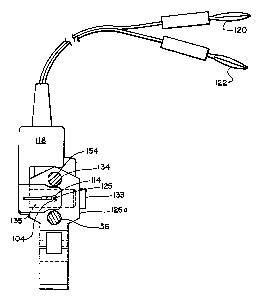
Fig. 15 is an enlarged side view of a power
to connector and a portion of a resectoscope handle.
Fig. 16 is an enlarged, side view, shown in
partial cross-section, of the power connector of Fig. 15.
Figs. 17a-17c are cross-sectional side views of
the electro-surgical device of Fig. 12 in use within a
urethra.
Structure
Referring to Figs. 1-4, particularly to Figs. la
and 1b, a transurethral resection assembly 10 includes a
resectoscope 28 and a bipolar electro-surgical device 11
2o having a loop-form resetting electrode 12 and a
coagulating electrode 14. When power is applied to the
device, the larger surface area of coagulating electrode
14 diffuses current to coagulate tissue over a large
region while the smaller surface area of resetting
electrode 12 concentrates current to resect immediately
adjacent tissue. Since the coagulating electrode 14 is
positioned ahead of the cutting electrode 12 along a line
of resection 24, tissue is coagulated just prior to
resection. Coagulating electrode 14 pivots (arrow 23)
3o with respect to resetting electrode 12 through cantilever
joint region 15 which controls the depth of resection and
coagulation.
Referring particularly to Figs. 2 and 3, the width
W2 of mounting fork 46 of coagulating electrode 14 and
the width W1 of mounting fork 48 of resetting electrode
CA 02559942 1996-O1-30
- to -
12 are substantially similar. As a result, mounting fork
48 engages mounting fork 46 to limit the maximum depth of
resection to avoid resection of tissue beyond the
coagulation zone, as will be described in more detail
s below.
Resecting electrode 12 and coagulating electrode
14 are connected by wire leads that extend through
electrical insulator jackets 16, 18, to a power source 21
(RF generator). The insulated leads extend in close
1o proximity through metal jacket 20 and are axially fixed
relative to each other and jacket 20 by epoxy fill 17.
Metal jacket 20 terminates proximally in articulation
ring 22a. Ring 22b is connected (not shown) to
resectoscope 28. Rings 22a and 22b are electrically
15 insulated from the electrodes and enable a physician to -
move metal jacket 20 and, hence, the electrodes within
lumenal space 26 of resectoscope 28 in an axial direction
along the resecting path 24.
The resectoscope also includes a telescope 30 that
2o images and illuminates resecting path 24. Telescope 30
is attached to metal jacket 20 through clip 32. As an
alternative, separate lumens (i.e., one for metal jacket
20 and one for telescope 30) are provided within
resectoscope 28. Additionally, lumenal space 26 is used
2s to irrigate and displace fluid (i.e., urine in the
urethra) in the area of resection. Preferably, lumenal
space 26 is filled with a non-osmotic, non-electrolytic,
high impedance fluid such as glycine (not shown). The
non-osmotic nature of glycine reduces damaging cellular
3o fluid absorption, and the non-electrolytic and high
impedance nature of glycine insures that the current
passed between the electrodes is focused in the tissue
between the two electrodes.
To reduce the cost of the procedure, distilled
water (i.e., deionized water) can be used instead of
CA 02559942 1996-O1-30
- 11 -
glycine. Like glycine, distilled water is non-
electrolytic. However, unlike glycine, distilled water
is osmotic. The substantially bloodless nature of the
procedure, however, significantly reduces the amount of
fluid absorbed by the patient. Hence, the osmotic nature
of distilled water does not typically pose a danger.
In a particular embodiment, resecting electrode 12
is tungsten and coagulating electrode 14 is a
silver/copper alloy, and the lead wires (not shown)
to within insulating jackets 16, 18, respectively, may be
made of many materials, including brass, a copper alloy,
or a silver alloy. Resecting electrode 12 has a loop-
wire diameter dl of 0.012 inches (Fig. 4), a length L1 of
0.30 inches (Fig. 2), and a height H of 0.325 inches
(Fig. 2). Coagulating electrode 14 is a cylindrical _
roller with a diameter d2 of about 0.125-0.187 inches
(Fig. 4) and a length L2 of between 0.187-0.25 inches
(Fig. 2). Electrodes 12 and 14 are separated by a
distance d3 of approximately 0.187 inches (Fig. 4).
2o Pivoting action of the electrodes can be facilitated by
making the mounting fork 48 of resecting electrode 12
stiffer than the mounting fork of coagulating electrode
14, e.g., by using a stiffer wire within insulating
jacket 18. Metal jacket 20 is made of stainless steel
25 and has an outer diameter of about 0.068 inches, a wall
thickness of about 0.005 inches, and an axial length of
about 8.0 inches. The power source is a surgical radio
frequency (RF) generator, generating a continuous sine
wave (i.e., cut waveform) and operating at a typical
3o frequency of lMHz and at typical power levels of 100-300
watts.
Use
Referring to Figs. 5-9, the operation of electro-
surgical device 11 will be described with regard to a
35 transurethral resectioning procedure (TURP). The
CA 02559942 1996-O1-30
- 12 -
patient is prepared by inserting a resectoscope to the
region of treatment. The physician, with a telescope and
irrigation, inspects the region. The region is then
flushed with glycine or distilled water.
Referring particularly to Fig. 5, the device 11 is
inserted into the patient's urethra 40 through the
resectoscope such that resecting electrode 12 and
coagulating electrode 14 extend from resectoscope 28.
When first inserted, cantilever joint 15 is fully open
1o such that coagulating electrode 14 rests on the surface
of tissue to be resected and resecting electrode 12 is
suspended a slight distance d4, approximately 0.'040
inches, above the surface of the tissue to be resected.
The separation is a safety factor since, if power is
is accidentally applied, current will not pass between the _
electrodes in a glycine or distilled water environment
until both electrodes contact the tissue surface.
Referring to Fig. 6, by applying an upward
pressure to the external end of resectoscope 28, as
2o indicated by arrow 42, the physician pivots coagulating
electrode 14 with respect to resecting electrode 12, as
indicated by arrow 44. This pivoting brings resecting
electrode 12 into contact with the tissue to be cut and
brings the fork 46 (Fig. 2) of coagulating electrode 14
2s closer to the fork 48 of resecting electrode 12.
Once both electrodes are in contact with the
surface of the tissue to be cut, the physician applies
power to the electrodes through hand or foot controls
(not shown). As discussed, both electrodes 12 and 14
3o must contact the tissue because the surrounding glycine
or distilled water will not conduct current. Current 50
flows through the tissue between the two electrodes. The
projected surface area (i.e., shadow or tissue contact
area) of coagulating electrode 14 is about 2-5 times
3s larger than the projected surface area of resecting
CA 02559942 1996-O1-30
- 13 -
electrode 12. As a result, the current density at
resecting electrode 12 is larger than the current density
at coagulating electrode 14. The larger surface area of
coagulating electrode 14 disburses current over a wide,
s deep area 29 and causes heating in the area sufficient
only to coagulate the tissue (i.e., approximately 60 -
100°C). On the other hand, the small surface area of
resecting electrode 12 concentrates the current density
and causes heating in adjacent tissue sufficient to
to resect the tissue. Typically, the heating induces a
vigorous vaporization in the area immediately adjacent
the electrode surface. (In some cases, a plasma~arc may
be generated in the area immediately adjacent the
electrode with temperatures of approximately 1000°C and
1s above. However, lower temperatures, without arcing, can _
be used for resection.)
Referring to Fig. 7, when the physician increases
the upward movement 42 of resectoscope 28, the electrodes
pivot bringing electrically insulated forks 46, 48 in
2o contact and causing resecting electrode 12 to resect the
tissue to its maximum depth Ml (Figs. 5 and 7). Since,
the length L2 (Fig. 3) of coagulating electrode 14 is
less than the width W1 of fork 48 the contact of both
insulated forks limits the maximum depth of resection.
2s The maximum depth of resection is limited to prevent
resection beyond the depth of coagulation. When forks
46, 48 are in contact, approximately half of coagulating
electrode 14 extends between the tines of fork 48. The
large surface area and low current density of coagulating
3o electrode 14 keeps coagulating electrode 14 from plunging
into the tissue.
Approximately 100-300 Watts of power applied to
the electrodes causes resecting electrode 12 to resect to
a maximum depth M1 of about 0.20 inches (0.5 cm) and
3s coagulating electrode 14 to coagulate to a maximum depth
CA 02559942 1996-O1-30
- 14 -
M2 of about 0.4 inches (1 cm). Coagulating 0.20 inches
deeper than resection insures substantially bloodless
resection.
Referring to Fig 8, the physician squeezes
s articulation rings 22a and 22b together to pull the
device 11 proximally. Coagulating electrode 14 rolls, as
indicated by arrow 50, along resecting path 24 and
resecting electrode 12 carves a chip 52 of tissue from
urethra 40.
to Referring to Fig. 9, in a typical transurethral
procedure, the resecting path is from the bladder to the
verumontanum in the prostate (approximately 1.5-10
inches). When the physician has reached the end of
resection path 24 (i.e., the point where the physician
1s wishes to stop resecting), either stops applying upward
pressure to resectoscope 28 allowing urethra 40 to cause
resectoscope 28 to move in a downward direction,
indicated by arrow 54, or directly applies a downward
force to move the resectoscope in the downward direction.
2o This causes cantilever joint 15 to spring open, indicated
by arrow 56, pivoting resecting electrode 12 upward and
away from coagulating electrode 14. (Because coagulating
electrode 14 travels ahead of resecting electrode 12
along the resecting path 24, a small portion-of
2s coagulated tissue 58 remains in place (i.e., not
resected).) During the procedure, the resected chips are
normally kept in the patient's bladder, and once the
resection is completed, the patient's bladder is
evacuated making sure to remove all of the resected
3o chips.
Another Structure
Referring to Figs. 12-14, another transurethral
resection assembly 100 includes a resectoscope 102 and a
bipolar electro-surgical device 104 having two closely
3s spaced, substantially similar loop-form electrodes 106,
CA 02559942 1996-O1-30
- 15 -
108. The thickness Tl, approximately 0.027", of loop
electrode 106 is slightly smaller than the thickness T2,
approximately 0.030", of loop electrode 108. As a
result, loop electrode 106 is the hot or cutting
s electrode while loop electrode 108 is the cold or return
electrode. When power is applied to the device, loop
electrode 106 concentrates the current density and causes
heating in adjacent tissue sufficient to resect the
tissue. The current 107 passing between the electrodes
is dispersed over a region of tissue in the area of the
incision and causes heating in the region sufficient only
to coagulate the tissue in the region. By applying
excessive power, approximately 125-300 Watts, to the
electrodes, the tissue in the area of the incision may be
coagulated to a depth sufficient to minimize or eliminate _
bleeding.
Spacing two substantially similar loop electrodes
a small distance d5, e.g., 0.027", apart provides a low
impedance path between the loop electrodes and insures
2o that the current passing between the loop electrodes is
confined to a short path. Confining the current path
permits safe high power, e.g., 125-300 Watts, electro-
surgery. Additionally, the electrodes are capable of
resecting tissue in a conductive liquid environment,
e.g., saline, because the current is focused in the
tissue between the electrodes and is not disbursed
through the conductive liquid.
Although coagulating tissue before or
substantially simultaneously with tissue resectioning
3o reduces fluid absorption via venous sinus, fluid
absorption may still occur. For example, in a myomectomy
procedure a tumor is resected from the uterus wall.
Prior to tissue resectioning, the uterus is pressure
distended with fluid which significantly increases the
likelihood of excessive fluid absorption. Excessive
CA 02559942 1996-O1-30
- 16 -
absorption of non-ionic fluids such as glycine can lead
to life threatening electrolyte imbalance. Resecting
tissue in an ionic liquid environment such as saline
reduces the risk of electrolyte imbalance.
Loop electrodes 106, 108 are connected by wire
leads that extend through electrical insulator jackets
110, 112 to electrical contact ring 114 and electrical
contact pin 116, respectively. The insulated leads are
axially fixed in parallel relative to each other. Ring
io 114 and pin 116 are electrically coupled with banana
plugs 120, 122, respectively, through a power connector
118. During operation, the banana plugs are connected to
an RF generator (not shown).
Pin 116 is inserted through a distal end 123 of a
metal jacket 124 in resectoscope 102 and into an aperture _
125 (Figs. 15 and 16) in power connector 118. The power
connector includes a knife edge lock 129 for grasping pin
116 and electrically connecting to pin 116 and a leaf
spring connector 131 for grasping ring 114 and
2o electrically connecting to ring 114. The resectoscope
includes a push-button release mechanism 133 that
operates through an aperture 135 in the power connector
to release pin 116 from lock 129.
An O-ring or a silicone membrane (i.e., diaphragm
or septum) 200 (Fig. 16) is placed at the opening 202 of
aperture 125 in power connector 118 to prevent liquid
from entering the power connector and forming a
conductive path between pin 116 and ring 114. Pin 116 is
passed through the O-ring, diaphragm, or septum when the
3o bipolar electro-surgical device is inserted within the
power connector.
After a procedure is complete and the resectoscope
is removed from the patient, electro-surgical device 104
is removed from the resectoscope using the push-button
release and may be thrown away or cleaned. Prior to the
CA 02559942 1996-O1-30
next procedure, a physician may insert a new or cleaned
electro-surgical device 104 within the resectoscope.
Use
Referring to Figs. 17a-17c, the operation of
s electro-surgical device 104 will be described with regard
to a transurethral resectioning procedure (TURF). The
patient is prepared by inserting a bullet-nosed obturator
(not shown) within a sheath 101 (Fig. 13) to the region
of treatment. The obturator is then removed from the
io sheath while leaving the sheath within the patient, and a
resectoscope and bipolar electro-surgical device assembly
is then inserted into the sheath. The assembly includes
a telescope 160 that is inserted through rail 134 and a
metal jacket 162 (Fig. 13) of resectoscope 102. With
15 telescope 160 and irrigation, the physician inspects the -
region. The region is then flushed with saline.
Resectoscope 102 includes a two-piece handle
having a proximal thumb piece 126a and a distal finger
piece 126b. Power connector 118 is attached to thumb
2o piece 126a. A physician inserts his thumb through ring
128 in thumb piece 126a and lays his fingers across
indentations 130a, 130b, 130c in finger piece 126b and
squeezes to slide (arrow 132, Fig. 17a) the thumb piece
along rails 134, 136 against a force (arrow 138) provided
2s by a spring 140. Sliding the thumb piece toward the
finger piece pushes bipolar electro-surgical device 104
through metal jacket 124 in the resectoscope to cause
electrodes 106, 108 to extend away from (arrow 142)
distal end 123 (Fig. 13) of resectoscope 102 and a distal
3o end 146 of sheath 101.
The physician applies power to the loop electrodes
by turning on the RF generator and applies an upward
pressure to the external end of resectoscope 102, as
indicated by arrow 147, to bring the electrodes in
3s contact with tissue 155. The physician then slowly
CA 02559942 1996-O1-30
18
releases his grip on the two-piece handle to allow the
thumb piece to move away from (arrow 148, Fig. 17c) the
finger piece and the electrodes to move back toward
(arrow 150) the distal end of the sheath. As the
electrodes are moved back toward the sheath, cutting
electrode 106 resects a chip 152 of tissue from a
resecting path 154 within the patient's urethra 156, and
current 154 passing between the electrodes coagulates
tissue in the area 157 of the incision. When the thumb
io piece of the handle is completely released, the
electrodes are pulled back into the sheath and chip 152
is cut off against a lower portion 158 of the distal end
of the sheath. The physician then either stops applying
upward pressure to resectoscope 102 allowing urethra 156
i5 to cause the.resectoscope to move in a downward _
direction, indicated by arrow 159, or directly applies a
downward force to move the resectoscope in the downward
direction.
other Embodiments
2o Many additional embodiments are possible. For
example, referring again to Figs. 15 and 16, power
connector 118 may be an adaptor power connector that is
attached to a resectoscope designed for use with a
monopolar electro-surgical device to allow a physician to
2s perform bipolar electro-surgery. The adaptor power
connector may be an insert molded part. The slide
distance d6 (Fig. 17a) is equal to the distance d7 which
the loop electrodes may be extended from the distal end
of the sheath. The width W3 of the adaptor power
3o connector is minimized to avoid decreasing the slide
distance.
As another example, the length L2 of coagulating
electrode 14 (Fig. 2) can be cut with grooves (not shown)
to increase the traction coagulating electrode 14 has
35 with the tissue surface. Similarly, the surface of
CA 02559942 1996-O1-30
- 19 -
coagulating electrode 14 can be polished to prevent
debris from sticking to coagulating electrode 14.
Instead of using a roller electrode for coagulation, a
sled electrode (i.e., does not roll, not shown) with the
s same surface area could be used. Coagulating electrode
14 is preferred, however, because as coagulating
electrode 14 rolls (i.e., turns in direction 50) it
prevents the build up of debris along resecting path 24.
In other embodiments, a fluid flow directly over
to the electrodes may be provided to wash away char that
could interfere with current flow. The flow could be
provided by, for example, a small tube running through
metal jacket 20 that terminates in a nozzle-form directed
onto the electrode surfaces. In another example, the
1s electrode and electrode lead could be hollow allowing _
fluid to flow and the working surface perforated such
that fluid weeps from the electrode to wash away char.
The fluid may be saline or another conductive fluid that
does not inhibit current flow. Washing fluid flow can be
2o initiated and terminated by a foot pedal, which may be
the same foot pedal that turns on power.
Referring to Figs. 10 and 1l, to avoid leaving
excess coagulated tissue region 58 in place at the end of
a cut, electrodes 12 and l4 can be configured to move in
2s an axial direction (i.e., along resection path 24)
independent of each other. This axial action can be
achieved by passing the insulated leads to the resecting
and coagulation electrodes through sperate lumens within
sheath 20. When the physician reaches the end of
3o resection path 24, the physician uses a mechanism to
independently push coagulating electrode 14 back along
resecting path 24 in an axial direction, indicated by
arrow 60, until coagulating electrode 14 is on an
opposite side of resecting electrode 12. As a result,
CA 02559942 1996-O1-30
- 20 -
coagulated tissue region 58 is removed as part of chip
52.
In order to move coagulating electrode 14 to an
opposite side of resecting electrode 12, the width W2
s (Fig. 2) of coagulating electrode 14 fork 46 is much
smaller than the width W1 of resecting electrode 12 fork
48. Additionally, to prevent the two electrodes from
coming in contact with each other, the length L2 of
coagulating electrode 14 is made less than the length L1
of resecting electrode 12.
Allowing electrodes 12 and 14 to move in an axial
direction independent of each other can also be used to
change the direction of resection. Urging coagulating
electrode 14 to an opposite side of resecting electrode
1s 12 allows for coagulation and resection along a resecting _
path in a direction opposite to resecting path 24.
Because a physician will normally carve several chips out
of the urethra in a transurethral procedure, by changing
the direction of the resecting path, the physician carves
2o a chip out with each push and then with each pull of the
device.
The electrodes may also include a flushing
apparatus to remove char. A tube 70, extending from
outside the device, terminates in a nozzle 72 that
2s directs a flow of saline onto the roller. The resecting
electrode is a hollow-form with perforations 74 through
which saline can weep onto the working surface.
Coupling and pivoting mechanisms, other than the
fork 46, 48 arrangement, can be employed. The maximum
3o depth of resection may not be limited by a stop
engagement. The resecting electrode can be constructed
such that the coagulation electrode can pass beyond the
mounting for the resecting electrode. If the width of
the fork of the coagulating electrode is less than the
3s width between the two loop halves of the resecting
s
CA 02559942 1996-O1-30
- 21 -
electrode, the depth of resection is not limited. Using
the telescope 30, the physician can manually control the
maximum depth of resection. Coagulation may be carried
out just after resection, by reversing the orientation of
s the electrodes.
The electro-surgical devices can be constructed
for use in various procedures, including endoscopic,
laparoscopic (i.e., the electrode configuration extends
through a trocar), and cystoscopic procedures. The
1o device can have a flexible shaft for delivery deep into
the body. The devices can be configured for removal or
debulking of tumors in, e.g., the esophagus, cervix, or
uterus (myomectomy), or for removal of liver lobe
sections or removal of any protruding vascular tissue.
i5 The devices may also be configured to resect the lining _
of the uterus (endometrioma) or for use in transurethral
resectioning of the bladder (TURB).
The devices can be constructed to carry multiple
different resecting and/or coagulating electrodes among
2o which power can be switched to vary the depth or width of
treatment. For example, the device may carry two
resecting loops arranged and of different size to allow
cutting to different maximum depths. Differently shaped
coagulating electrodes can be carried to vary the
2s coagulation pattern. By switching among the different
electrodes, the physician can tailor the treatment
without removing the device from the body. The different
electrodes can be arranged in parallel about or in series
along the device axis. The power applied to the device
3o can be varied with device construction and purpose
(tissue type). Small scale devices, e.g., for use in the
brain, may use lower power settings, e.g., 10 Watts. The
arrangement can be adapted for a handheld device for use
in open surgery. Moreover, the resecting electrode can
3s be replaced faith a different shaped small surface area
CA 02559942 1996-O1-30
- 22 -
resecting electrode, and the coagulating electrode can be
replaced with a different shaped larger surface area
coagulating electrode.
Other embodiments are within the following claims.