Note : Les descriptions sont présentées dans la langue officielle dans laquelle elles ont été soumises.
CA 02560515 2004-12-13
RING SLICER WITH EASILY REMOVABLE KNIFE AND KNIFE ASSEMBLY
Field of the Invention
The present invention relates to a ring slicer having an easily removable
knife and
knife assembly, particularly for use in slicing or flaking logs, refuse
lumber, chips, or other
articles of wood in a lumber mill.
Background of the Invention
Ring slicers, also termed ring flakers or stranders, are generally used in
manufacturing
facilities for manufacturing particle board, oriented strand board, and
fiberboard such as
MDF. They convert logs, refuse lumber, chips, or other articles of wood into
flakes, wafers
or strands for the manufactured board products. The ring slicer includes a
cylindrical ring
assembly for revolution about an axis of rotation. The ring assembly typically
includes a
large number of elongate knife assemblies, commonly 49 but which may be as
many as 72.
The knife assemblies support elongate knives having cutting edges extending
parallel to the
axis of rotation captured between annular end plates. The ring assembly
rotates within a
chamber into which pieces of wood to be cut or chipped are introduced.
The knives are subject to wear from the wood, and in addition rocks, metal
objects
and other hard foreign material carried by or with the wood also wear the
knives, and may
damage or
CA 02560515 2004-12-13
break the knives as well as the knife assemblies. Accordingly, it is routinely
required to remove
the knives to repair or replace them, or to turn them to expose fresh cutting
edges. Moreover, it
is episodically required to remove and replace some or all of the knives, the
knife assemblies, or
both; as a result of "crashes" of the ring dicer apparatus. The machine
downtime and the labor
required to effect maintenance and repair are costly and desirably kept to a
bare minimum.
As described in U.S. Patent No. 5,313,696, the knives may be mounted to a
portable knife
assembly that slides radially into slots in the end plates of the ring
assembly. Once in place, bolts
are inserted through holes in the end plates into threaded holes in the knife
assembly to hold the
knife assembly in place. In turn, the knife is similarly mounted to the knife
assembly with bolts
extending through holes in the knife into threaded holes in the knife
assembly.
One problem with this approach is that the bolt holes require a tolerance that
permits the
knife or knife assemblies to move or creep within the ring assembly and
thereby to become
misaligned or to loosen as a result of the large cutting forces encountered
during operation.
Moreover, removing the knife from the ring slicer requires both removing the
knife assembly
from the ring assembly and removing the knife from the knife assembly.
To hold the knife assembly more securely to the ring assembly, the knife
assembly may
be provided with protruding keys that extend axially into corresponding
keyholes in the end
plates. The keys and keyholes can be provided with a minimal tolerance of fit
that maintains the
positional integrity of the knife assembly. However, a major disadvantage of
this approach is
that the knife assemblies may no longer be simply slid radially away from the
ring assembly for
maintenance or repair. Rather, the end plates must be axially spaced apart a
su~cient amount to
permit the projecting keys to clear the end plates, requiring that the
entirety of at least one end
2
6
CA 02560515 2004-12-13
plate be decoupled from all of the knife assemblies.
It is often necessary to remove a knife from the knife assembly under
conditions where it
is not otherwise necessary to remove the knife assembly from the ring
assembly. U.S. Patent No.
5,937,923 addresses this problem by providing a clamp for the knife that is
biased outwardly by
springs disposed in spring holes in the knife assembly, for unclamping the
knife without
requiring removal of the clamping bolts.
A disadvantage of the mechanism is that it requires the clamp to move
radially, and while
a necessary indexing of the clamp is provided to seat the clamp into proper
position when it is
tightened, this is provided in the form of sliding surfaces that wear over
time so that the position
of the clamp and; therefore, the knife are permitted to wander.. Another
disadvantage of the
mechanism is that it is difficult to remove cut wood fibers introduced into
the spring holes when
the clamp is loosened. It is yet another disadvantage of the mechanism that
the spring forces
produced by the multiple compression springs must be well matched to prevent
binding of the
clamp.
Accordingly, there is a need for a ring dicer having an easily removable knife
and lulife
assembly that provides for positive maintenance of the position of the knife
in the ring slicer as
well as easy removal of the knife and knife assembly therefrom.
Surnmary of the Invention
The invention disclosed herein is a ring slicer having an easily removable
knife and knife
assembly. According to one aspect of the invention, there is an assembly for
clamping a knife,
the knife having two sides, the assembly comprising a base and a clamp for
clamping the knife to
3
CA 02560515 2004-12-13
the base. The clamp includes an upper clamping member for mounting to the base
so that a
portion of the upper clamping member is cantilevered from the base. The upper
clamping
member includes provision for at least one bolt extending through the portion
into the base such
that tightening the bolt elastically deflects the upper clamping member
against one side of the
knife.
According to another aspect of the invention, there is an assembly for
clamping a knife,
comprising a base and a clamp. The clamp includes an upper clamping member for
mounting to
the base and a wearshoe for separately mounting to the base. The clamp is
adapted for clamping
the knife between the upper clamping member and the wearshoe. The wearshoe and
the base
include cooperatively interlocking portions adapted to resist relative motion
between the
wearshoe and the base in a first direction. Alternatively or in addition, the
wearshoe and the base
include cooperatively ramping portions adapted to resist relative motion
between the wearshoe
and the base in one direction.
According to yet another aspect of the invention, there is an apparatus for
cutting an
article of wood, comprising a ring assembly and a plurality of knife
assemblies. The ring
assembly comprises two end plates for rotation about an axis of rotation. Each
of the knife
assemblies comprises an elongate knife having a cutting edge extending along
an elongate axis, a
base, and a clamp for clamping the knife to the base. The knife assemblies are
adapted for
installation between the end plates such that the shoulder portions of at
least two shoulder bolts
extend through one of the end plates into the base. Preferably the knife has
dual cutting edges.
4
CA 02560515 2004-12-13
Brief Description of the Drawings
Figure 1 is a front, partially cut-away view of a prior art ring dicer.
Figure 2 is a plan, section view of the ring dicer of Figure l, taken along a
line 2-2
thereof.
Figure 3 is a partially cut-away, elevational view of a prior art knife
assembly for the ring
slicer of Figures 1 and 2.
Figure 4 is a pictorial view of a ring assembly according to the present
invention.
Figure S is a pictorial view of a knife assembly according to the present
invention.
Figure 6 is an end view of the knife assembly of Figure 5.
Figure 7 is the end view of Figure 6 showing selected phantom lines.
Figure 8A is a top pictorial view of a knife for use in the knife assembly of
Figure 5.
Figure 8B is a bottom pictorial view of the knife of Figure 9A.
Figure 9 is a pictorial view of the knife assembly of Figure 5, showing
partial removal of
the knife therefrom.
Figure 10 is a pictorial view of the knife assembly of Figure 5, showing
complete removal
of the knife therefrom.
Figure 11 is a pictorial view of a portion of the ring assembly of Figure 4,
showing
removal of the knife assembly therefrom.
Figure 12 is a side elevation of the knife assembly of Figure 5.
Figure 13 is a pictorial view of a portion of an alternative ring assembly
according to the
present invention.
CA 02560515 2004-12-13
Figure 14 is an end view of an alternative knife assembly according to the
present
invention.
Detailed Description of a Preferred Embodiment
Referring to Figures 1 and 2, a prior art ring sliver 12 is shown, such as
disclosed in U.S.
Patent No. 5,937,923. The ring sliver has a ring assembly 10 that is caused to
rotate about an
axis of rotation "L." The ring assembly 10 has a number of cutting knife
assemblies 16 for
cutting and chipping pieces of wood 9 that flow in the direction indicated as
"F" in Figure 2) into
the apparatus through an opening 11. The ring sliver also includes a "rotor"
14 that counter-
rotates with respect to the ring assembly 10 about the axis "L," to sling the
pieces of wood 9
against the knives of the ring assembly. A drive mechanism 13 includes
respective motors (not
shown) for driving the rotor through an arbor shaft 15 and for driving the
ring assembly 10
through a coaxially disposed drive-shaft 16. The knife assemblies 16 are
captured between two
annular rings 18 (not shown in Figure 1 ).
The ring sliver 12 is particularly adapted to manufacture particle board;
however, with
suitable adaptation the ring sliver may be used to manufacture oriented strand
board as well.
While either of these are preferred contexts for the present invention, the
principles of the
invention may be applied to any cutting apparatus, particularly any cutting
apparatus for
processing articles of wood.
Turning to Figure 3, a prior art knife assembly 16 is shown, captured between
the two
annular rings 18 of the ring assembly shown in Figure 2. The knife assembly 16
has an elongate
body 21 to which is directly bolted, by use of bolts 15a, an elongate knife 23
having a cutting
6
CA 02560515 2004-12-13
edge 24. The body includes threaded holes at ends 26a, 26b thereof for bolting
the body between
the rings 18 by use of bolts 15b. The body also includes respective projecting
keys 27 at the ends
for extending into mating keyholes in the rings, the reversal of the keys and
keyholes being
functionally equivalent. While the bolts 15 hold the ring assembly together,
the keys and
keyholes are used to locate the knife assemblies with respect to the rings and
thereby prevent
creep of the knife assembly resulting in misalignment during use. A similar
strategy could be
used to key the knife 23 to the body 21.
To remove the knife 23 from the knife assembly 16 when it is installed between
the rings
18 requires complete removal of all of the bolts 15a of the knife assembly. To
remove the knife
assembly 16 from the ring assembly 10 requires removing the bolts 1 Sb,_
and.moving the rings 18
axially far enough apart so that the projecting keys 27 clear the inside faces
29 of the rings 18 so
that the knife assembly can be slid outwardly from the ring assembly. This
latter step requires at
least loosening and typically completely removing the bolts 15b for every
knife assembly in the
ring assembly. Where there are typically 49 or as many as 72 knife assemblies
in the ring
assembly, this is an objectionably laborious and time consuming process.
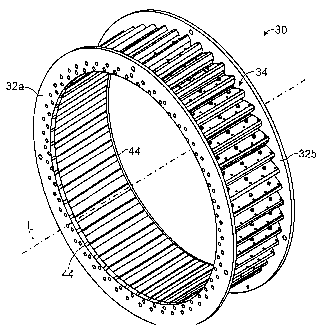
Turning to Figure 4, a ring assembly 30 according to the present invention is
shown that
substantially reduces the time and labor required to change either the knives
of the knife
assemblies, or the knife assemblies themselves.
The ring assembly 30 includes two end plates 32a, 32b which are preferably but
not
necessarily annular in shape. Captured between the two end plates 32 are a
plurality of
individual knife assemblies 34. There are typically 49 knife assemblies, but
the number of knife
7
CA 02560515 2004-12-13
assemblies may vary considerably. For example, ring slicers are available with
as few as 32
knife assemblies and as many as 72 knife assemblies.
Figures S and 6 show a knife assembly 34 according to the present invention.
The knife
assembly includes a knife 36, a clamp 38 and a base 40. The clamp 38 includes
an upper
clamping member 38a and a wearshoe 38b that functions as a lower clamping
member. Both the
wearshoe and the upper clamping member are bolted to the base such as shown in
Figure 7. A
preferred knife 36 for use in the knife assembly 34 is also shown in Figures
8A and 8B.
The knife 36 is clamped to the base 40 by the clamp 38. Particularly, the
knife is held
between the upper clamping member 38a and the wearshoe 38b. The upper clamping
member is
bolted to the base 40 by use of a bolt 45a, and the wearshoe is bolted to the
base by use of a bolt
45b (Figure 7). However, the knife is not yet held by the clamp 38 until a
clamp bolt 45c is
tightened.
Particularly, the base has a raised support portion 42 (Figure 6) on which one
end of the
upper clamping member 38a is supported. The upper clamping member is
cantilevered out from
this support and without any deflection is spaced apart from the wearshoe by a
distance "d" that
is greater than the thickness "t" of the knife. Tightening the clamp bolt 45c
therefore deflects the
cantilevered upper clamping member 38 elastically so as to bring it into
contact with the knife,
and further tightening of the clamp bolt tightens the clamp. Accordingly,
loosening the clamp
bolt 45c releases the clamping force on the knife and the upper clamping
member relaxes its
elastic deflection, freeing the knife for easy removal from the knife assembly
34. The cantilever
arrangement of the upper clamping member provides the outstanding advantage,
as compared to
prior art spring-clamp mechanisms, of being unaffected by packing and
manufacturing tolerance.
8
CA 02560515 2004-12-13
This is because the cantilever can be deflected despite any cut wood fibers
caught between the
upper clamping member and the base, and because the entire upper clamping
member functions
as a single spring, the characteristics of which do not have to cooperate with
those of any other
spnngs.
Preferably, there is about a 0.004" to 0.008" clearance between the upper
clamping
member 38 and the knife when the clamp bolt 45c is fully loosened and,
therefore, the upper
clamping member 38 is in its relaxed, undeflected, state. , Multiple instances
of the clamp bolt
45c are preferably provided such as shown in Figure S to ensure that the
required clamping force
can be exerted and maintained.
The wearshoe 38b and the base 40 advantageously include cooperatively
interlocking
portions 41 and 43 respectively, that function to index, strengthen and secure
the attachment of
the wearshoe to the base. Particularly, the interlocking portions 41 and 43
prevent movement of
the wearshoe with respect to the base in the direction indicated as "A," and
thereby ensure that
the distance "d" is and remains fixed.
Referring to Figures 9 and 10, the knife 36, once unclamped by loosening the
clamp
bolts) 45c, can be installed into or removed from the knife assembly 34 in the
direction of the
arrows. Turning back to Figure 4, these operations can be accomplished while
the knife
assembly is still in place in the ring assembly 30 simply by sliding the knife
axially out of the
ring assembly 34 through a corresponding slot 44 (see also Figure 11) in the
end plates 32. It is
an outstanding advantage of the ring assembly 30 that neither the clamp bolts
nor the knife
assembly needs to be removed in order to remove the knife.
Preferably, slots 44 corresponding to a particular knife assembly 34 are
provided on both
9
CA 02560515 2004-12-13
end plates 32a and 32b (Figure 11), so that the knife may be conveniently
removed through one a
slot in one of the end plates, e.g., 32a, by pushing another knife into place
through the
corresponding slot in the other end plate. For example, a knife 36 may be
pushed into the knife
assembly 34 while the knife assembly is installed in the ring assembly 10 of
Figure 11 through
slot 44b in the end plate 32b, which will act to push the knife akeady in the
knife assembly 34
out the slot 44a of the end plate 32a.
Turning to another aspect of the invention, Figures 6, 9, 10 and 11 show dowel
pins 48
extending from the base 40. Referring to Figure 12, the dowel pins 48 are
slidingly disposed in
dowel holes 50 in the base and extend into or through dowel holes S 1 in the
end plates 32. Bolts
45d (see also Figure 7) extend through the end plates 32 into holes 53 (Figure
6) in the base to
hold the ring assembly together. The dowel pins are tight-fitting in the
respective dowel holes,
but are preferably slidingly movable therein by pressing or punching the pins
with hand tools.
The dowel holes extend deeply enough into the base that the dowel pins may be
pressed or
punched into the holes and wholly contained thereby, so that outer ends 49 of
the dowel pins may
be substantially flush with or beneath an outer end surfaces 51 of the base.
Accordingly, if the
length of the dowel pins is "L,," the depth of the dowel holes "L2," is
preferably at least as great
~ "L »
In the ring assembly 30, the dowel pins are ordinarily positioned to extend
from the dowel
holes, into or through the plates 32, to locate the base 40 to the plates 32.
However, to remove
the knife assembly 34 from the ring assembly, the dowel pins on at least one
end of the knife
assembly may be pressed or punched into the dowel holes so that the knife
assembly is free to
slide radially out of the ring assembly. It is an outstanding advantage of the
ring assembly 30
CA 02560515 2004-12-13
that the knife assembly can be removed from the ring assembly simply by
removing the bolts 45d
and pressing or punching the dowel pins on at least one end of the knife
assembly into their
respective dowel holes.
Figure 13 shows an alternative knife assembly 60 according to the present
invention
along with a portion of the ring assembly 10 to which it is to be attached.
Like the knife
assembly 10, the knife assembly 60 has a la~ife 36, a clamp 62 and a base 64.
The knife 36
preferably includes dual cutting edges 36a and 36b (seen in end-view in Figure
13). The clamp
62 includes an upper clamping member 62a and a wearshoe 62b that functions as
a lower
clamping member. Both the wearshoe and the upper clamping member are bolted to
the base as
shown in Figure 14. The knife 36 is preferably the same as the knife described
above in
connection with the knife assembly 10, and the knife is preferably clamped to
the base in the
same manner.
The wearshoe 62b and the base 64 advantageously include cooperatively
interlocking
portions 71 and 73 respectively, that function to index, strengthen and secure
the attachment of
the wearshoe to the base. Particularly, the interlocking portions 71 and 73
prevent movement of
the wearshoe with respect to the base in the direction indicated as "A." The
cooperatively
interlocking portions are preferably angled at an angle ~ of about 45 - 60
degrees defined as
shown.
In addition, the wearshoe and base include cooperatively romping portions 75
and 77
respectively, that function to further prevent movement of the wearshoe
relative to the base.
Particularly, the romping portions are oriented at an angle 8 defined relative
to the longitudinal
axes "LA" of bolts 74 and 76 that secure the wearshoe to the base;
particularly
11
CA 02560515 2004-12-13
with respect to the perpendicular to these axes which in the embodiment shown
15 parallel to the
direction "A." The angle 8 is positive (defined as shown) and shallow,
preferably about 5
degrees. In response to the force exerted by the bolts, the positively angled
ramping portions
tend to prevent movement of the wearshoe with respect to the base in the
direction perpendicular
to the axes "LA", which is indicated as "B."
Turning back to Figure 13, an alternative means for attaching a knife assembly
to the ring
assembly 10 is shown. The ring assembly has two annular rings 18a and 18b (not
shown). One
end of the base 64 has at least two holes 66a and 68a, and the associated ring
18a has a
corresponding set of holes 66b'and 68b, for receiving a corresponding set of
at least two shoulder
bolts 70 and 72 that extend through the ring 18a. Preferably, corresponding
sets of holes and
shoulder bolts are provided at the other end of the knife assembly that is not
shown.
The holes 66 and 68 provide a close tolerance clearance fit, e.g., 0.002", to
shoulder
portions 70a and 72a of the shoulder bolts, for aligning the knife assembly to
the ring assembly.
The holes 66 and 68 terminate in threaded portions (not shown) that receive
the corresponding
threaded portions 70b and 72b of the shoulder bolts, for bolting the knife
assembly to the ring
assembly. Head portions 70c and 72c of the shoulder bolts are preferably
received by and seat in
counterbored holes 80 in the ring 18a, though this not essential.
Each shoulder bolt provides the advantage of both aligning and attaching the
knife
assembly to the ring assembly. The two (or more) shoulder bolts together
provide a greater
degree of alignment and strength with less installation effort than prior art
attaching means
comprising separate alignment pins and bolts. While the shoulder bolts are
shown for use with
12
CA 02560515 2004-12-13
the knife assembly 60, they may be used .in place of the dowel pins of the
knife assembly 10 as
well, and may be used to equal advantage in other alternative knife
assemblies.
It is to be recognized that, while a particular ring slicer having an easily
removable knife
and knife assembly has been shown and described as preferred, other
configurations and methods
could be utilized, in addition to those already mentioned, without departing
from the principles of
the invention.
The terms and expressions which have been employed in the foregoing
specification are
used therein as terms of description and not of limitation, and there is no
intention in the use of
such terms and expressions to exclude equivalents of the features shown and
described or
portions thereof, it being recognized that the scope of the invention is
defined and limited only by
the claims which follow.
13