Note : Les descriptions sont présentées dans la langue officielle dans laquelle elles ont été soumises.
CA 02560991 2006-09-22
WO 2005/099604 PCT/US2005/008793
~G'NE FIXATION IMPLANTS
FIELD OF THE INVENTION
(0001] The present invention generally relates to implants for bone fixation
such as
plates and meshes, and more particularly to improved implants having for
example an
indicator that permits the top surface of the implant to be more easily
detected during
surgery.
BACKGROUND OF THE INVENTION
[0002] Biologically compatible metallic and resorbable implants, such as
differently
shaped plates and meshes, have been used in crani.ofacial surgical bone repair
applications.
Such implants are used to mend bone discontinuities resulting from trauma-
induced
fractures or osteotomies necessitated by various surgical procedures. These
implants are
commonly secured to the bone with various types and shapes of fasteners, such
as screws
and tacks. Craniofacial plating has been offered in a variety of
configurations including
plates with straight-sides (as shown in FIG. 1) or undulating sides being
wider at the
fastener holes than between the holes (as shown in FIG. 2). The undulating
plate design
provides desirable bending characteristics ensuring that such plates bend
between the
fastener holes (typically the weakest part of the plate) and allows such
plates to be readily
contoured to match the shape of the bone to which they will be secured.
[0003] Unlike metallic bone implants which have been commonly used, resorbable
plates offer many desirable properties that are particularly well adapted for
certain surgical
applications, such as those involving craniofacial bone repair. For instance,
resorbable
plates retain their necessary strength for a predetermined period of time
following
implantation to allow the bone discontinuity (resulting from a traumatic
fracture or
intentional incision made for other surgical purposes) to mend. After the
implant has served
its useful structural purpose and preferably when the bone has satisfactorily
mended, these
resorbable implants dissolve and are absorbed by the patient's body through
natural
mechanisms such as hydrolysis. This is especially advantageous for patients
such as
children and young adults where bone development and growth is still
occurring. In these
young patients, resorbable implants may be indicated to avoid some potential
complications
associated with metallic implants which are not absorbed by the body and may
impede
normal bone development or migrate from the original location if not removed
by a second
surgery.
-1-
CA 02560991 2006-09-22
WO 2005/099604... ,Resorb,at~le i~~~~a~~s may be made from various
ma~ePCT/US2005/008793
polymers and combinations of two or more polymers to create copolymers,
terpolymers, etc.
The selection of individual and combinations of various polymers, methods used
to
manufacture the polymers and bone implants themselves, and other factors may
affect the
functional properties of the resorbable implants, such as how long structural
strength and
dimensional stability is retained after implantation and the time required for
complete
absorption.
[0005] Resorbable materials are generally relatively rigid and inflexible at
ambient
operating room and human body temperatures. As inherent with many polymers,
resorbable
materials become more flexible and bendable when their temperature is elevated
to a
temperature above the glass transition temperature (T~ of the material.
Accordingly,
resorbable implants may be bent to match the contour of the bone surface to
which they will
be attached by first heating the implant to a temperature above the glass
transition
temperature (Tg) and below the melting point of the material by means such as
a water bath,
heating wand, hot air blower, or other suitable method known in the art. When
the
temperature of the implant is allowed to fall back below the glass transition
temperature
(T~ of the material, the implant will return to its initial substantially
rigid condition and
hold the shape into which it has been formed.
[0006] Unlike much larger metallic implants commonly used for orthopedic
fracture
fixation of long bones such as the femur and humerus, both resorbable and
metallic bone
implants used in craniofacial applications are significantly shorter in
length, narrower, and
thinner. They are sometimes referred to as mini plates in the art. For
example, some
craniofacial plates may typically be less than 1 inch in length, about 1/4
inch or less in
width, and less than 1/8 inch in thickness. In addition, resorbable implants
(e.g., plates and
meshes) are relatively translucent and semi-transparent in appearance which
may make it
difficult for some surgeons to readily distinguish the top and bottom surfaces
of the implant.
Thus, the size of these craniofacial implants and/or the type of material used
to make the
implants (e.g., resorbable polymers) can make it cumbersome for some surgeons
to quickly
identify the top surface of the implant during surgery. This is especially
important for
proper installation where the fastener holes do not have a constant diameter
between the
upper and lower surfaces of the implant, but may for example have countersunk
holes
intended to receive fasteners having heads of a corresponding shape.
Improvements in
packaging and labeling implants have attempted to solve this problem, but
these measures
have had only limited success.
-2-
CA 02560991 2006-09-22
WO 2005/099604 PCT/US2005/008793
., ,. . ~E,~; ;,._;G ET~~S,~;.tl~~~~:~s~;~a~y~e~~i for bone implants that can
proviaG mG ~ur~cen wmn
direct and positive indication of the top surface of the implant to facilitate
proper surgical
installation of the implant onto the bone.
SUMMARY OF THE INVENTION
[0008] The invention relates to a bone implant that is configured and
dimensioned to
provide positive indication of the top surface of the implant via tactile
means. Implants
according to principles of the present invention generally comprise a top
surface, a bottom
bone-contacting surface, and at least one recessed region or portion disposed
in the top
surface of the implant to provide a tactile indicator for readily identifying
the top surface of
the implant. In one embodiment, the top surface indicator may be in the form
of an
elongated groove that is recessed below the top surface of the implant.
Preferably, the top
surface groove may be U-shaped in cross-section; however, other suitable cross-
sectional
shapes are contemplated and may be used as a matter of design choice. Also
preferably, the
top surface groove extends only partially through the thickness of the implant
to distinguish
the top surface from the bottom surface. In one embodiment, the implant is
made from a
resorbable material.
[0009] In one embodiment, the implant has at least one elongate plate section.
In
other embodiments, the implant incorporates at least one or more elongate
plate sections
and has a form which may be an L-shape, a Y-shape, a double Y-shape, an X-
shape, or
other numerous shapes which may be formed by combining various elongate plate
sections.
[0010] It will be appreciated by one skilled in the art that depending on the
shape
and size of the implant, a plurality of recessed top surface portions may be
provided and
arranged in numerous layout patterns when looking at the plate in plan view
from above. In
one embodiment, for example, a mesh plate implant may have a plurality of
crossing
elongated recessed portions arranged diagonally, parallel, or in a combination
thereof to the
sides of the mesh plate. In addition, the recessed portion itself may be
provided in any
number of cross-sectional shapes and combinations of shapes thereof without
limitation. In
one preferred embodiment, for example, the recessed top surface groove may
have a U-
shaped cross-sectional shape in the form of a square or rectangular channel.
[0011] The implant may further include at least one fastener hole extending
from the
top surface to the bottom surface of the implant. A variety of screws, tacks,
or similar
fasteners may be installed through~the holes to affix the implant to the bone.
Preferably, at
least two holes are provided. The fastener holes may have straight walls
forming a constant
diameter hole from the top to bottom surface of the implant. Preferably, the
top surface of
-3-
CA 02560991 2006-09-22
WO 2005/099604s~ ~ ,~ , ,~.~ PCT/US2005/008793
..,~- ....-~ __.. yT~""~~ ~(i;;~k giias around the fastener holes such than me
neaas of
fasteners inserted therethrough may be substantially flush with the top of the
implant.
[0012] The implant may also have chamfered side edges to provide additional
tactile
indication of the top surface of the plate. These chamfered edges also allow
the implant to
be less palpable after implantation.
[0013] It will be appreciated by one skilled in the art that providing a
recessed
portion in the top surface of an implant, such as a longitudinal groove
discussed above, may
alter the implant' flexural rigidity and out-of plane bending properties
because the section
modulus of the implant is affected by its cross-sectional dimensions and
shape. The term
"out-of plane" is defined as the direction normal to the top or bottom
surfaces of the
implant. In addition, in the case of some prior elongate bone plate designs
having
undulating sides such as that shown in FIG. 2, it may be necessary to
concomitantly widen
the plate between the fastener holes to physically accommodate an elongated
top surface
groove or channel as described above. Thus, according to another aspect of the
present
invention, it has been determined that advantageously adding transverse
openings
(preferably such as slots or slits, for -example) partially across the width
of the bone plate
may be used as a means to adjust or control the out-of plane bending
characteristics of the
plate. Accordingly, where an elongated top surface groove is added to an
existing plate
design to provide top surface indication accordingly to principles of the
present invention,
transverse openings may be used in conjunction with the surface groove if the
designer
wishes to maintain comparable out-of plane bending characteristics.
Alternatively, it will
be appreciated that transverse openings may also be used alone with equal
benefit in bone
plates not having an elongate surface.indication groove as a means to regulate
the bending
and flexural rigidity characteristics of the plate. Accordingly, the use of
transverse openings
is not limited to use with top surface indication recesses.
[0014] In light of the foregoing, therefore, a bone plate formed according to
another
aspect of the present invention may also comprise a top surface, a bottom
surface, a
plurality of fastener holes, a recessed portion in the top surface of the
plate, and at least one
transverse opening running across the width of the plate. The bone plate may
comprise at
least one elongate plate section. The recessed portion is preferably an
elongate groove;
however, other shapes are contemplated. In one embodiment, the elongate groove
extends
at least partially between two fastener holes. The transverse opening may be
elongate, and
in the form of a slit or slot, for example. In some embodiments, the
transverse slots may be
preferably oriented perpendicular to the longitudinal axis of the plate.
Preferably, the
-4-
CA 02560991 2006-09-22
WO 2005/09960 ~~~~~s..~,~~~~e~~~~~~ed between at least some of the
fasPCT/US2005/008~93
preferably, the transverse openings may extend both at least partially across
the width of the
plate and partially through the thickness of the plate. More preferably, the
transverse
openings extend all the way through the plate from the top surface to the
bottom surface. In
preferred bone plate embodiments having a plurality of fastener holes, the
transverse
openings may be provided between at least some of the fastener holes. In
another
embodiment, a bone plate with bending control includes at least one elongate
tranverse slot
as described above, but does not include a tactile top surface indicator in
the form of an
elongate groove or recessed region. Bone plates with bending control may be
made from
any suitable biocompatible material as described herein, including a
resorbable material.
[0015] It should be recognized that the transverse openings also
advantageously
promote elongate plates to bend between, and not at the fastener holes. The
fastener holes
are typically the weakest part of the plate and experience the highest
stresses caused by
external loads imposed on the plate after implantation. Thus, it is preferable
that such plates
bend between the fastener holes to reduce the likelihood of failure.
[0016] In another embodiment, a bone plate with bending control formed
according
to principles of the present invention comprises a top surface and a bottom
bone-contacting
surface, at least two fastener holes defining a longitudinal axis therebetween
and disposed in
the plate extending from the top surface to the bottom surface of the plate,
and at least one
elongate slot disposed in the plate and extending from the top surface to the
bottom surface
of the plate. The elongate slot preferably may be disposed between the two
fastener
openings and extends transverse to the longitudinal axis. The elongate
transverse slot
affects the bending characteristics of the plate and induces the plate to bend
between the
fastener holes.
A method of contouring and attaching resorbable implants having top surface
indicators to the bone is also provided. The method comprises the steps of:
providing a
resorbable implant having a glass transition temperature (Tg) that is higher
than average
human body temperature, the implant comprising a top surface and a bottom bone-
contacting surface, at least two fastener holes extending from the top surface
to the bottom
surface, and a portion of the top surface being recessed and extending
partially between the
top and bottom surfaces, whereby the top surface recess provides a tactile
indicator for
identifying the top surface of the implant; raising the temperature of the
implant to above
the glass transition temperature (Tg); touching the surfaces of the plate to
find the top
surface recess thereby identifying the top surface; deforming the plate to
substantially
-5-
CA 02560991 2006-09-22
WO 2005/099604 ~ PCT/US2005/008793
k.~,,,__~~.~,.-.~_ y~.",~,~e~=~~oc~is_,~ap~~ ~a~'the bone with the top surface
facing away uu~n me
bone; applying the plate to the bone; and attaching the plate to the bone. The
method may
further include providing fasteners and inserting the fasteners through at
least some of the
fastener holes, wherein the fasteners are used for attaching the plate to the
bone. In one
embodiment, the fasteners are screws or tacks.
[0017] A bone fixation kit as described hereafter is also provided. In
general, the kit
may comprise at least a first bone implant and fasteners for securing the
implant to a bone.
Preferably, the implant may have a recessed region in the top surface to
provide a tactile
indicator for identifying the top surface of the implant. The implant and/or
fasteners may be
made from a resorbable material. ' In other embodiments, the kit may include
at least a
second and at least a third bone implants. Accordingly, the kit may include
without
limitation a combination of any number, sizes, design, and/or shapes of bone
implants and
fasteners as described herein.
[0018] It will further be appreciated by one skilled in the art that the
invention is
particularly useful for craniofacial skeleton surgical implants, including
such implants that
are made of biologically compatible metals (stainless steel, titanium, etc.),
resorbable
materials, composite materials, and other suitable implant materials known in
the art.
Preferably, implants formed according to principles of the present inventions
may be made
from resorbable materials, discussed in more detail below.
[0019] It should be noted that use of the invention is not limited to
craniofacial
applications, nor is the manufacture of the invention limited to the foregoing
materials.
Accordingly, the invention may be used for any type of implant where it is
desirable to
provide a positive tactile indication of the top surface of the implant and/or
control the
bending characteristics of the implant.
BRIEF DESCRIPTION OF THE DRAWINGS
[0020] The features and advantages of the present invention will become more
readily apparent from the following detailed description of the invention in
which like
elements are labeled similarly, and in which:
[0021] FIG. 1 is a top plan view of a straight prior art bone plate;
[0022] FIG. 2 is a top plan view of an undulating prior art bone plate;
[0023] FIG. 3A is a top plan view of an implant in the form of a bone plate
formed
according to principles of the present invention having a top surface
indicator;
[0024] FIG. 3B is a cross-sectional view taken along line 3B-3B in FIG. 3A;
-6-
CA 02560991 2006-09-22
,W0,20~05/099604~~,. ~~"~~,'~.~~m~s~ectional view taken through a
fasterPC_T_/US2005/008793
3C-3C in FIG. 3A;
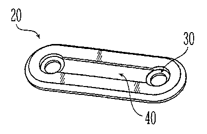
[0026] FIG. 3D is a perspective view of the bone plate of FIG. 3A;
[0027] FIG. 3E is a cross-sectional view of the bone plate of FIG. 3A having
an
alternative V-shaped embodiment of a top surface indicator;
[0028] FIG. 3F is a cross-sectional view of the bone plate of FIG. 3A having
an
alternative concave-shaped embodiment of a top surface indicator;
[0029] FIG. 4 is a side view of a screw useable with the implant of FIG. 3A
having
a head configured to mate with the fastener holes of the implant of FIG. 3A;
[0030] FIG. 5 is a top plan view of a different embodiment of a bone plate
according
to the present invention having four fastener holes;
[0031] FIG. 6A is a top plan view of another,embodiment of a bone plate
according
to principles of the present invention having a top surface indicator,
transverse slots, and a
plurality of fastener holes;
[0032] FIG. 6B is a cross-sectional view taken through a fastener hole along
line
6B-6B in FIG. 6A;
[0033] FIG. 7 is a top plan view of another embodiment of an implant formed
according to principles of the present invention in the form a strut plate
having top surface
indicators and transverse slots;
[0034] FIG. 8 is a top plan view of another embodiment of an implant formed
according to principles of the present invention in the form of an orbital rim
plate having a
top surface indicator and transverse slots;
[0035] FIG. 9 is a top plan view of another embodiment of an implant fornned
according to principles of the present invention in the form of a left L-plate
having a top
surface indicator and transverse slots;
(0036] FIG. 10 is a top plan view of another embodiment of an implant formed
according to principles of the present invention in the form of a right L-
plate having a top
surface indicator and transverse slots;
[0037] FIG. 11 is a top plan view of another embodiment of an implant formed
according to principles of the present invention in the form of a Y-plate
having a top surface
indicator and transverse slots;
[0038] FIG. 12 is a top plan view of another embodiment of an implant formed
according to principles of the present invention in the form of a double Y-
plate having a top
surface indicator and transverse slots;
CA 02560991 2006-09-22
WO 2005/099604;.. ~~;T~ , ~.~,~s~;~ t~rp,,plview of another embodiment ofPCT~
YS2005/00879u
u,.,1 .,i 1~ 1~~ ~ ,
according to principles of the present invention in the form of an X-plate
having a top
surface indicator and transverse slots;
[0040] FIG. 14 is a top plan view of another embodiment of an implant formed
according to principles of the present invention in the form of a burr hole
cover plate having
a top surface indicator and transverse slots;
(0041] FIG. 15A is a top plan view of another embodiment of an implant formed
according to principles of the present invention in the form of a resorbable
mesh plate
having a top surface indicator;
[0042] FIG. 15 B is a cross-sectional view taken through a fastener hole along
line
15B-15B in FIG. 15A having a top surface indicator;
[0043] FIG. 16 is a side view of a tack useable with all implants similar to
the one
depicted in FIG. 3A having a head configured to mate with the fastener holes
of the implant
of FIG. 3A; and
(0044]_ FIGS. 17A-Q depict several different components that may, in any
number
of combinations, compose a bone implant kit with surface indicator.
DESCRIPTION OF THE PREFERRED EMBODIMENTS
[0045] In the description that follows, any reference to direction or
orientation is
merely intended for convenience of description and is not intended in any way
to limit the
scope of the present invention. Moreover, the features and benefits of the
invention are
illustrated by reference to the preferred embodiments. Accordingly, the
invention expressly
should not be limited to such preferred embodiments illustrating some possible
non-limiting
combination of features that may exist in alone or in other combinations of
features, and
which should only be limited by the claims appended hereto.
[0046] FIGS. 3A-D depict one embodiment of an implant for bone fixation in the
form of a bone plate. The bone plate 20 has a generally elongate body defining
a
longitudinal axis LA extending along the centerline of the plate, and a
transverse axis TA
extending perpendicular to the longitudinal axis. Plate 20 includes two ends
21, a top
surface 22, a bottom bone-contacting surface 24, two longitudinally extending
sides 26
connecting the top to bottom surfaces, and two ends 21. Preferably, ends 21
are rounded in
shape (as shown) to avoid possible soft tissue irritation, but ends 21 may
have any suitable
configuration. The distance between the top surface 22 and bottom surface of
plate 20
defines a thickness T for the plate. Preferably, thickness T is substantially
constant from
_g-
CA 02560991 2006-09-22
~;,d I~ a ~d o~ ~~ ~'~,~~C~4~tc~~~fi~i.~~~~h'er'~°~n~, but it may vary
along the longitud naiUax s LA,ghe
transverse axis TA, or both.
(0047] Preferably, at least two fastener holes 30 are provided in plate 20
which may
be located near the ends 21 of the plate. Holes 30 extend from the top surface
22 to the
bottom surface 24 and are configured to receive a fastener to attach plate 20
to the bone.
FIG. 3C, a cross-sectional view taken from FIG. 3A, shows one preferred
embodiment of a
countersunk fastener hole 30. Starting at the top surface of plate 20, hole 30
preferably has
a conical countersunk shape comprising a first inclined wall 32, followed by
an adjacent
second inclined wall 34, and followed again by a straight-wall that penetrates
the bottom
surface 24 of plate 20. First inclined wall 32 of hole 30 has a different
angle B 1 than second
inclined wall 34 which has an angle B2. Preferably, B 1 is about 15-25
degrees, preferably
about 20 degrees, and 82 is about 130-150 degrees, preferably about 140
degrees.
[0048] It should be noted that the number of fastener holes 30 provided are
typically
dictated by the length of the bone plate and the number of possible fastener
mounting
locations intended to be provided, both being generally a matter of design
discretion.
(0049] It should be noted that hole 30 may be of any suitable shape and is not
limited to the shape described above. For example, hole 30 may be conical
countersunk in
shape with only a single inclined wall, or hole 30 may have entirely straight
walls without
any countersunk portion, or hole 30 may be be spherical in cross-sectional
shape.
Accordingly, the present invention is not limited by the shape of hole 30.
(0050] The conical countersunk hole 30, as shown in FIG. 3C, may be preferably
used with fasteners having a matching fastener head configuration with double-
inclined
walls. For example, screw 50 (shown in FIG. 4) may be used in hole 30 and has
a threaded
shank 54 and head 51 with inclined surfaces 52, 53 corresponding in shape to
inclined walls
32, 34 of hole 30, respectively. Accordingly, screw head 51 inclined surfaces
52, 53
preferably have angles al and a2 to match angles B 1 and B2 of hole 30,
respectively. The
top of screw head 51 may be slightly convex, as shown. An advantage of the
mating screw
and fastener hole configurations is that the top of the screw is substantially
flush with the
top surface 22 of plate 20 when the screw 50 is installed in countersunk hole
30 (except for
the slight convexity of the top of the screw head 51). This helps reduce
possible soft tissue
irritation when plate 20 is implanted, and the screw heads S1 cannot readily
and separately
be felt beneath the skin by the patient, particularly in locations where there
is a relatively
thin skin coverage over the bone, such as in craniofacial applications.
-9-
CA 02560991 2006-09-22
WO 2005/099604..., ~ , E, ,. " PCT/US2005/008793,
~EUtU:SlI~ .:'' a.:.~~ rt:~~~ ~ioth~~ ~~rilidc'yiiriient shown in FIG. 16, a
fastener WAG mm m a ~a~~
160 may also used in fastener hole 30 of plate 20. Tack 160 has a head 166 and
corrugated
shank 168 with corrugations 162 running substantially transverse to the
longitudinal axis of
the tack. Tack head 166 may have a straight side surface 164 and an inclined
surface 162
which forms an angled transition to shank 168. At least a portion of inclined
surface 162
has an angle a2 that cooperates with angle B2 of hole 30, thereby matching the
shape of
inclined wall 34 of hole 30 in a similar fashion to screw 50 discussed above.
Tack 160 is
used by the surgeon drilling a hole in the bone that is slightly smaller in
diameter than the
outermost diameter of coiTUgations 162. Tack 160 is then pressed into the bone
hole and
held in place by a friction fit.
[0052] Referring again to FIGS. 3A-F, plate 20 further comprises a recessed
surface
region or portion that serves as a top surface indicator. Preferably, the
recessed region is
separate from the fastener holes; however, the recessed region may intersect
and incorporate
one or more fastener holes. In one embodiment, the top surface indicator is a
longitudinally
extending elongate groove 40 that is recessed below the top surface 22 of
plate 20.
Preferably, top surface groove 40 extends at least partially along the length
L of plate 20,
partially across the width W of plate 20, and preferably partially through the
thickness T of
plate 20 to distinguish the top surface 22 from the bottom surface 24. Also
preferably, top
surface groove 40 extends between the fastener holes and more preferably,
completely from
one hole 30 to the other hole.
[0053] Top surface groove 40 provides a tactile indicator making it easier for
a
surgeon to identify the top surface 22 of plate 20 by touch. This helps to
ensure that the
plate 20 is properly attached to the bone such that the countersunk fastener
holes 30 are
facing upwards for receiving bone screws 50 or tacks 160. Although top surface
groove 40
is particularly useful with implants such as plate 20 described above where
the fastener
holes are not symmetrical at the top and bottom surfaces of the implant, it
will be
appreciated that top surface groove 40 is not limited to such applications and
may be used
with any implants where it is desirable to identify the top surface of the
implant.
(0054] In one preferred embodiment, top surface groove 40 may be U-shaped in
cross section (best seen in FIG. 3B) having a substantially planar bottom
surface 42 and
planar sidewalls 41. Preferably, the depth GD and width GW of top surface
groove 40 is
sufficient to allow a surgeon or other individual to easily identify the top
surface 22 of the
plate by tactile touch during a procedure; preferably, while the surgeon or
other individual
may be wearing latex gloves. Also preferably, the bottom surface 24 of plate
20 may have a
-10-
CA 02560991 2006-09-22
WO ~005~0996~04'~~t~,E~.O,f~~~ ~t~ la~;~i;~~;te differentiating the opposite
gr oveaUop susr~iage9lZ of
plate 20 from the bottom.
[0055] Although top surface groove 40 may preferably be channel shaped, it
will be
appreciated that top surface groove 40 may have various other suitable cross-
sectional
configurations, such as but not limited to a V-shaped groove 37 (see FIG. 3E),
concave-
shaped groove 38 (see FIG. 3F), etc. Thus, other shaped grooves are
contemplated. In
addition, it will be appreciated that depth GD and width GW of top surface
groove 40 may
be varied as a matter of design choice. Accordingly, the invention is not
limited with
respect to either the shape or size of top surface groove 40. Also preferably,
elongated top
surface groove 40 is disposed along the centerline of plate 20 which coincides
with the
longitudinal axis LA, as shown in FIG. 3A. However, the location of groove 40
is not
limited in this regard and other locations are contemplated.
[0056] Referring to FIG. 3B, at least a portion of the sides 26 and/or ends 21
of plate
20 may have an edge chamfer 28 to provide an additional tactile indicator for
identifying the
top surface 22 of the plate. The chamfered edge also allows the implant to be
less palpable
a$er implantation. Preferably, the chamfer 28 extends completely around plate
20. Also
preferably, the chamfer has an angle 23 of about 40-50 degrees, more
preferably about 45
degrees, to the top surface 22 of plate 20.
[0057] In one embodiment of a straight elongate plate, the elongate portion of
the
plate (see, e.g., FIGS. 3A, 5, and 6A) may typically be approximately 0.8 mm
thick T by 6
mm wide W and have a top surface groove 40 typically measuring about 2.0 mm
wide GW
by 0.3 mm deep GD (dimensions +/- allowances for manufacturing tolerances). In
another
embodiment of a straight elongate plate, the elongate portion of the plate for
receiving 2.0
mm nominal diameter bone fasteners may typically be approximately 1.2 mm thick
by 7
mm wide with about a 2.0 mm wide by 0.3 mm deep top surface groove 40. The
length L
of the bone plates may be varied as a matter of design choice and the specific
anatomical
skeletal portions intended for the plates.
[0058] FIG. 5 depicts another embodiment of the present invention comprising a
bone plate similar to plate 20 as shown in FIGS. 3A-D, but with four fastener
holes 30
instead of two. Plate 60 may be longer than plate 20, and the additional
fastener holes
provides extra mounting flexibility and/or security in attachment to the bone.
Preferably,
top surface groove 40 extends at least between the innermost rivo fastener
holes 30. More
preferably, top surface groove 40 connects all four fastener holes 30.
-11-
CA 02560991 2006-09-22
WO 2005/099604 CT/US2005/008793
".,r;---,~ : ,. .. ,~.T ~:~~~r~ri:r~~ r~pv~°to_.uFyG. 6A-C, there is
shown another eP~~~~ul~~mm m a Done
plate according to the present invention incorporating transverse openings
which may be in
the form of slits or slots, as discussed above. The number, size, and location
of the
transverse slots or slits allow the designer to control the bending
characteristics of the plate.
A straight elongate bone plate 70 incorporating transverse slits or slots may
comprise a
plurality of fastener holes 30 (see FIG. 3C), and preferably a longitudinally
extending top
surface groove 40 that extends between the fastener holes. Generally elongate
transverse
slots 72 extend preferably transverse to the longitudinal axis LA of plate 70
and preferably
between the fastener holes 30. Preferably, transverse slot 72 intersects top
surface groove
40 and preferably extends from the top surface 22 to the bottom bone-
contacting surface 24
of plate 70. However, slot 72 alternatively may extend only partially between
the top
surface 22 to the bottom bone-contacting surface 24 of plate 70. Also
preferably, a plurality
of elongate transverse slots 40 are provided and evenly spaced between at
least some of the
fastener holes 30.
[0060] Although FIGS. 6A-C depict a relatively close fastener hole 30
arrangement
with one transverse slot 72 disposed between each pair of holes 30, the
invention is not
limited in this regard. Accordingly, any number and spacing of fastener holes
30 may be
used with any number and spacing of transverse slots 72, all being a matter of
design
choice. For example, elongate plate 20 shown in FIG. 3A may include transverse
slots 72.
In addition, transverse slits or slots 72 may be provided for elongate
implants that do not
have a top surface indicator such as elongate top surface groove 40. Moreover,
more than
one transverse slot 70, which may be of different configuration and
orientation, may be
provided between fastener holes 30.
[0061] As discussed above, transverse slots 40 promotes elongate plates such
as
plate 70 to bend between, and not at the fastener holes 30 which typically are
the weakest
points in the plate and experience the highest bending stresses. In addition,
transverse slots
40 allow the designer to control. the bending characteristics of the plate and
the plate's
flexural rigidity. Also as noted above, it will be understood that altering
the dimensions,
shape, and number of slots 72 provides the designer with a means to alter the
bending
characteristics of the plate.
[0062] With reference to FIGS. 6A and 6B, transverse slots 40 in one
embodiment
may typically measure about 0.8 mm in width SW by about 2.5 mm in length SL.
(0063] The implants of the present invention may be made from any
biocompatible
material, including, but not limited to metals, resorbables, composites (i.e.,
combinations of
- 12-
CA 02560991 2006-09-22
WO, 2005/099604 ~,]~.~~ith~~,~~~aar~ai;~e~ated or laminate construction),
etcP~_T_/US2005/008793~e,
implants of the present invention may preferably be made from any suitable
resorbable (i.e.,
biodegradable and bioabsorbable) material. These materials eventually dissolve
over time
following implantation and are absorbed by the patient's body. More
preferably, the
implants may be made from polymer-based resorbables including, but are not
limited to,
one type of polymer, combinations of two or more different polymers to create
various
copolymers, terpolymers, etc., polymer alloys, composites having multiple
layers of
resorbable polymers, polymers containing resorbable reinforcement fibers, etc.
The
selection of material and individual or combinations of various polymers,
methods used to
manufacture the polymers and implants, and other factors affect the functional
properties of
the resorbable implants, such as how long structural strength and dimensional
stability is
retained in vivo after implantation and the time required for complete
absorption of the
implant by the patient's body.
[0064] Resorbable polymeric materials are generally somewhat rigid and
inflexible
at ambient operating room and human body temperatures. Such polymers typically
become
more flexible and bendable when their temperature is elevated to a temperature
above the
glass transition temperature (Tg) and below the melting point of the material.
Accordingly,
resorbable implants may be bent to match the three-dimensional contour of the
bone surface
to which they will be attached by heating the implant to a temperature above
the glass
transition temperature (Tg) and below the melting point of the material by
means such as a
water bath, hot air gun, in situ bending/cutting iron, or other suitable means
lrnown in the
art. Once the resorbable implant has been contoured and secured in place on
the bone,
rigidity returns as its temperature drops below the glass transition
temperature (Tg).
[0065) Preferably, an implant formed according to principles of the present
invention may be made from polymers such as lactide and glycolide, and
copolymers of the
same. More preferably, the implant is made of 70/30 poly (L, D/L-lactide)
copolymer or
85/15 poly (L-lactide-co-glycolide) copolymer compositions. These compositions
have
desirable mechanical and resorption properties, such as sufficiently long in
vivo strength
retention after implantation to allow sufficient time for bone mending to
occur.
(0066] It will be appreciated that processing of the raw polymeric materials)
and
manufacturing methods can effect the properties of the polymers and implants.
(0067] Preferably, an implant made from the 70/30 poly (L, D/L-lactide)
copolymer
composition may be fully resorbed within approximately 3 years +/- after being
implanted.
An implant made from the 85/15 poly (L-lactide-co-glycolide) copolymer
composition may
-13-
CA 02560991 2006-09-22
WO 2005/099604 PCT/US2005/008793 ,
~~~~ra~bay.b:~!~f~T~%..~.~-'~esti~?~~f~G. .".w'~'ul.r~~.pproximately 1 year +/-
after being nnplanted. It mll
be appreciated that the thickness of the implant, its geometric configuration,
and individual
patient's body chemistry may affect the resorption times.
[0068] Implants formed according to principles of the present invention may be
made from polymers that are crystalline or amorphous (i.e., non-crystalline)
in structure,
depending on the specific raw polymeric materials) selected to fabricate the
implant,
processing of the raw polymeric material(s), and method used to manufacture
the finished
implant, all of which are a matter of design choice. Thus, the crystallinity
of the polymer
raw material and finished implant may be varied as a matter of design choice.
In one
embodiment, the polymer raw material of the 70/30 poly (L, D/L-lactide)
copolymer
composition (i.e., before the implant is formed) has a raw material
crystallinity preferably of
approximately 10-12%. In another embodiment, the copolymer raw material of the
85/15
poly (L-lactide-co-glycolide) copolymer composition (i.e., before the implant
is formed)
preferably has a crystallinity of approximately 15-35%.
[0069] The materials and implants according to principles of the invention may
also
contain or be impregnated with various additives, fillers, chemical and
biologically-active
agents (i.e., antibiotics, pharmaceuticals, proteins, etc.), surface
treatments, etc. to alter
and/or facilitate the processing, manufacture, properties, and/or performance
of the
materials and implants. The implant may further be coated with materials that
contain or
are biologically active agents, antibiotics, medicinals, growth factors, etc.
[0070] Resorbable polymeric implants made according to principles of the
present
invention are preferably compression molded in one embodiment. Preferably,
fasteners
used to secure implants of the present invention to the bone are also made
from resorbable
materials, preferably the same polymeric resorbable material from which the
implants are
made. The fasteners, however, may also be made from different resorbable
materials than
the implants. Preferably, the fasteners may be injection molded.
(0071] Implants made from the foregoing 70/30 poly (L, D/L-lactide) copolymer
and 85/15 poly (L-lactide-co-glycolide) copolymer compositions preferably have
a glass
transition temperature (T~ that is above ambient operating room and human body
temperatures. 1n one embodiment, the glass transition temperature Tg is at
least about 50
degrees C. As noted above, resorbable polymers are generally somewhat rigid
and
inflexible below th.e glass transition temperahue Tg. When heated to
temperatures above
the glass transition temperature Tg and below the melting point of the
material, the
-14-
CA 02560991 2006-09-22
WO 2005/099604 PCT/US2005/008793
resorbdbte ~i~h~rs!'b'ec~i~ ~iio'~~..~~exible and may readily be bent by 1116
~~..~~~V11 w
conform to the anatomical shape of the bone intended to receive the implant.
(0072] Implants of the present invention are preferably made, without
limitation, by
cutting the implants from a compression molded plain sheet of resorbable
material. In one
embodiment, the plain sheet may typically measure 150 mm square. A single
sheet may
yield more than one implant or plate, and the top of the sheet may become the
top surface of
the finished implants or plates. All features of the plates are preferably
similarly cut or
machined into the implants at the factory, including top surface grooves,
fastener holes,
edge chamfers, transverse slots, etc.
[0073] Implants of the present invention are not limited in shape to the
generally
elongate straight bone plates discussed above, which are used merely for
convenience to
describe some possible illustrative and non-limiting preferred embodiments of
the
invention. Thus, numerous other implant configurations are possible that may
be formed
according to the principles of the present invention. For example, as shown in
FIGS. 7-16,
other possible shapes without limitation are double-wide broadened strut
plates, curved
orbital rim plates, L-plates, Y-plates, double Y-plates, X-plates, burr hole
covers, box plates
and meshes. Some of these implants may comprise portions or sections of two or
more
individual generally elongate straight plates described heretofore that are
combined to create
various other configurations.
[0074] Other possible embodiments of implant shapes according to principles of
the
present invention will now be briefly described.
(0075] FIG. 7 shows another embodiment of the present invention in the form of
double-wide strut plate. Generally elongate plate 80 is similar to plate 70
shown in FIG.
6A; however, plate 80 has a double row of both holes 30 and top surface
grooves 40. Plate
80 preferably includes countersunk holes 30, elongate top surface grooves 40
extending
between at least some of the holes, transverse slots 72, and side edge chamfer
28.
[0076] FIG. 8 shows another embodiment of the present invention in the form of
a
curved orbital rim plate. Generally elongate plate 90 is similar to plate 70
shown in FIG.
6A; however, plate 90 has a slightly curved arc-like shape with a radius 92 to
match the
average shape of the orbital rim for use in reconstructive surgery of the bone
involving the
eye socket. In one embodiment, radius 92 is preferably about 32 mm, but may
vary
infinitely to match patient anatomy. Plate 90 also preferably includes
countersunk holes 30,
elongate top surface groove 40 extending between at least some of the holes,
transverse
slots 72, and side edge chamfer 28.
-15-
CA 02560991 2006-09-22
WO 2005/099604 PCT/US2005/008793
[~O~f"~] ° ""~'~~:'~'sh'ovtv~"~of~i~r embodiment of the present
invention in the form of an
L-plate. Generally plate 100 comprises two elongate plate sections each
similar to the plate
70 shown in FIG. 6A; however, one plate is disposed at an angle to the other
plate. Plate
100 has an elongate body portion 102 and an elongate head portion 104 disposed
at an angle
106 to the body portion. Preferably, angle 106 is at least 90 degrees, but may
be any angle
greater or less than 90 degrees. More preferably, angle 106 is an oblique
angle greater than
90 degrees. In one preferred embodiment, angle 106 is about 100 - I 10
degrees. In the
embodiment shown, body portion 102 is preferably longer than head portion 104.
Both
body portion 102 and head portion 104 also each preferably include countersunk
holes 30,
elongate top surface groove 40 extending between at least some of the holes,
transverse
slots 72, and side edge chamfer 28. It should be noted that plate I00 of FIG.
9A may
conveniently be referred to as a left oblique L-plate.
[0078] FIG. 10 shows another embodiment of the present invention in the form
of a
right oblique L-plate. Plate 110 is similar to left oblique L-plate 100, but
is generally a
mirror image of plate I00. Accordingly, right oblique L-plate 110 has an
elongate body
portion 112 and an elongate head portion 114 disposed at an angle 116 to the
body portion.
The other features of L-plate 1 IO (i.e., fastener holes 30, elongate top
surface groove 40,
transverse slots 72, side edge chamfer 28) are essentially the same as in L-
plate I00.
[0079] FIG. 11 shows another embodiment of the present invention in the foixn
of a
Y-plate. Generally plate 120 comprises three elongate plate sections each
similar to plate
70 and combined in the manner shown in FIG. 11. Plate 120 has an elongate body
portion
122 and an elongate first head portion 124 and an elongate second head portion
126. Angle
I28 is formed between first and second head portions 124, 126, respectively.
Preferably,
angle 128 is less than or equal to about I80 degrees. More preferably, angle
128 is about
70-110 degrees, and even more preferably about 90 degrees. In the embodiment
shown,
body portion I22 is preferably longer than either first head portion 124 or
second head
portion 126, but is not limited in its length with respect to first and second
head portions
124, 126. Also preferably, first head~portion 124 is about the same length as
second head
portion 126. However, the length of the first head portion 124 may be
different than second
head portion 126. Both body portion 122 and first and second head portions
124, 126 each
preferably include countersunk holes 30, elongate top surface groove 40
extending between
at least some of the holes, transverse slots 72, and side edge chamfer 28.
(0080] FIG. 12 shows another embodiment of the present invention in the form
of a
double Y-plate. Generally plate 130 comprises four partial elongate plate
sections each
- 16-
CA 02560991 2006-09-22
WO 2005/099604 . , T .. , h .. ~ PCT/US2005/008793
A'... (Lrt°. F ~ I~ .
~iiz~=lad to ~l~a~f~ ~7t~~°c!oinl~'~~~1 es s~Q~.vn in FIG. 12. Plate
130 has a central body portion 132
which may have a substantially flat uninterrupted surface as shown.
Alternatively, body
portion 132 may contain fastener holes 30, a top surface groove 40, and
transverse slots 72
(not shown). An adjacent first head portion 134 and a second head portion 136,
combined
in a manner similar to first and second head portions I24, I26 in plate 120
(see FIG. 11), are
provided at either ends of body portion 132. Angle 138 is formed between first
and second
head portions 134, 136, respectively. Preferably, angle 138 is less than or
equal to about
180 degrees. More preferably, angle 138 is about 70-110 degrees, and even more
preferably
about 90 degrees. In the embodiment shown, preferably first head portion 134
is about the
same length as second head portion 136. However, the length of the first head
portion 134
may be different than second head portion 136. First and second head portions
134, 136
also each preferably include countersunk fastener holes 30, elongate top
surface groove 40
extending between at least some of the holes, transverse slots 72, and side
edge chamfer 28.
[0081] FIG. 13 shows another embodiment of the present invention in the form
of
an X-plate. Generally plate 140 comprises a central body portion 142 defining
a common
hub and four elongate arm portions 144 extending radially outward therefrom.
Plate 140
may be viewed as formed by combining two intersecting elongate plate sections
each
similar to plate 20 and arranged generally perpendicular to each other. Each
arm portion
144 is preferably disposed without limitation at an angle 148 of about 90
degrees to an
adj acent arm portion 144. Each arm portion 144 also preferably includes
countersunk
fastener holes 30, elongate surface groove 40 extending between at least some
of the holes,
transverse slots 72, and side edge chamfer 28., Arrn portion 144 may
preferably have a
slightly enlarged area 146 around countersunk hole 30 in contrast to that part
of arm portion
144 connected to central body portion 142, as shown. Enlarged area 146
provides
additional strength to arm portion 144 in the areas surrounding the fastener
hole 30 which
are typically the weakest part of a bone plate. As shown, body portion 142 may
not contain
any fastener holes or transverse slots, but may include elongate top surface
grooves 40 as
shown to provide indication of the top surface of the plate. Alternatively,
body portion 142
may include transverse slots and/or fastener holes (not shown).
(0082] FIGS. 14A and 14B show another embodiment of the present invention in
the form of a burr hole cover plate. These plates are typically used in
conjunction with
craniotomies wherein several spaced-apart round holes are drilled through the
skull which
are subsequently connected by osteotomies therebetween to create a bone flap.
Generally
plate 150 shown in FIG. 14A comprises a generally central body portion 152
defining a
-17-
CA 02560991 2006-09-22
WO 2005/099604 PCT/US2005/008793
;~~~=,~u~~~~.~ ~lr~~;~i~,~;plt~r~ ~; ~,a~~s 154 extending radially and
angmar~y uurwara
p nr
therefrom, preferably in a spiral pattern. Preferably, central body portion
152 is circular in
shape. In one embodiment as shown, plate 150 preferably may have eight arms
154.
However, it will be appreciated that any number of arms may be provided. The
arms may
extend radially outward directly in line with the plate's "radius" or the arms
may extend
outwardly out of line with the plate's radius, creating angle 157b as shown in
Figure 14A.
It will be appreciated that arms extending out of line with the radius creates
more space in
between the respective arms for tool usage and therefore allows for a plate
with more arms.
In one embodiment, the angle 157b preferably may be about 10 to about 20
degrees, more
preferably about 15 degrees, although other angles are contemplated. Each arm
154
includes a fastener hole, which preferably may be disposed on the end of each
arm and may
be a countersunk fastener hole 30. Fastener holes 30 maybe uniformly
distributed and
radially spaced apart around the circumference of body portion 152.
Preferably, each
fastener hole 30 of an embodiment with eight arms 154 is spaced apart at angle
157a of
about 45 degrees. It will be appreciated that the angle 157a between arms 154
will depend
in part on the number of arms provided. As shown, each arm 154 is preferably
connected to
center portion 152 at a region 159 that is circumferentially offset from the
radial centerline
158 of fastener hole 30 originating in the center of burr hole cover plate
150. Plate 150 also
preferably includes a side edge chamfer 28.
[0083] Body portion 152 of bun hole cover plate 150 may further have a surface
recess 151 that is recessed below the top surface 153 of body portion 152, and
serves as a
top surface indicator for plate 150. Preferably, surface recess 151 extends
only partially
between top surface 153 and bottom surface 155 of body portion 152 (best seen
in FIG.
14B). In the embodiment shown, surface recess 151 is preferably circular in
shape;
however, it should be noted surface recess 151 may have any suitable shape and
is not
limited to circular shapes alone. In lieu of a single top surface recess 151,
plate 150 may
alternatively have two or more top surface recesses in any number of shapes
and arranged in
a variety of patterns in central body portion 152 (not shown).
[0084] Although burr hole cover plate 150 is depicted in FIG. 14A as having 8
arms
154, any suitable number of arms may be provided. Accordingly, plates 150 with
fewer or
more arms may be provided and are contemplated within the scope of the
invention.
Preferably, arms 154 are arranged in a spiral pattern similar to that depicted
in FIG. 14A to
facilitate fabrication of the plate by providing improved access for tooling
needed to form
the arms.
-18-
CA 02560991 2006-09-22
WO 2005/099604. , ~", PCT/US2005/008793
r~:,;~~~ ~~~;. d~,,~ :;mu ~;'~~.~5~:' f~~~~,a~d;;~~~3 shows another embodiment
of the present invention in
the form of a substantially flat mesh plate. Generally mesh plate 160
comprises a top
surface 162 and bottom surface .164. Optionally, mesh plate 160 may further
include a side
edge chamfer 28, as shown. A plurality of fastener holes 30 extend through
mesh plate 160
from top surface 162 to bottom surface 164. At least one elongate top surface
groove 40
extends between at least some of the holes 30. Preferably, two or more top
surface grooves
40 are provided and arranged in a suitable pattern to allow the surgeon to
readily detect.top
surface 16 of mesh plate 160. Although top surface grooves 40 are shown as
preferably
being oriented diagonally (with respect to the sides of mesh plate 160) and
arranged in a
fairly uniform pattern in the embodiment illustrated in FIG. 15A, it will be
appreciated that
any suitable number, orientation, or pattern may be formed with top surface
grooves 40 as a
matter of design choice. The invention is therefore not limited to the top
surface groove
configuration or pattern shown herein, and other configurations and patterns
are
contemplated.
[0086] FIG. 17 shows several different components that may, in any number of
combinations, compose a bone fixation kit including embodiments comprising at
least a first '
bone implant, such as for example a bone plate, comprising a top surface and a
bottom
bone-contacting surface, at least two fastener holes extending from the top
surface to the
bottom surface, and the top surface having a recessed region that provides a
tactile indicator
for identifying the top surface of the implant. In one embodiment, the kit
further includes a
plurality of fasteners (see, e.g., FIGS. 17N-Q) for attaching the implant to a
bone. In one
embodiment, the top surface recess region is elongate in shape. In another
embodiment, the
implant includes at least one elongate plate section. The implant may have a
form which
includes an L-shape, a Y-shape, a double Y-shape, an X-shape, or any other
style implant
required for a specific procedure in another embodiment. Exemplary implant
styles are
shown in FIGS 17A-M. The implant may also further comprise a length and a
width, and at
least one transverse slot located between the at least two fastener holes and
extending across
at least part of the width of the implant. Preferably, the implant is made
from a resorbable
material. In one embodiment, the fasteners may be screws or tacks. Exemplary
screws and
tacks are shown in FIGS. 17N-Q. The aforementioned embodiments are merely
exemplary
and, thus, this invention should not be limited to the styles or quantities
shown. A kit
could be custom tailored to a surgeon's preferences or to a particular
procedure.
[0087] The kit may fizrther include at least a second implant, which may be
the same
as the first implant, or different such as, for example, in shape, design,
material, and/or
-19-
CA 02560991 2006-09-22
WO 2005/099604 1 d ~; ~j~:~~ e;; i,e outside dimensions). The ki~u ayUa
ju0ui008~e at
least a third implant the same as or different from the first and second
implants. It will be
appreciated that a kit according to principles of the present invention may
have any number
and types of implants and/or fasteners. Accordingly, numerous variations in
components of
the kit are possible. The kit may also include various instruments to aide in
the contouring
and implantation of the implant. For example, the kit may include instruments
such as, but
not limited to, drill bits, taps, screwdrivers, scissors, cutters, and tack
drivers.
[0088] A method of contouring and implanting resorbable implants formed
according to principles of the present invention will now be described with
reference to
FIG. 3A and plate 20 for convenience. The same method, however, applies to
other
embodiments formed according to principles of the present invention disclosed
herein.
Plate 20, preferably housed in sterile packaging and having the features
described above, is
provided to the surgeon in its initial rigid and flat two-dimensional form. In
the surgical
arena, the surgeon first determines the implant reception site on the bone and
necessary
final three-dimensional shape of plate 20 based on the anatomical three-
dimensional shape
of reception site. The surgeon next heats resorbable plate 20 to above its
glass transition
temperature (Tg) to make the plate malleable by any suitable means commonly
known in the
art, such as a hot water bath, hot air gun, in situ bender/cutter iron, etc.,
as discussed above.
Preferably, the glass transition temperature (T~ is above ambient operating
room and
human body temperatures. Preferably, the glass transition temperature (Tg) of
the
resorbable polymeric material is greater than average normal human body
temperature
(oral) of about 98.6 degrees Fahrenheit (37 degrees C) so that the implant
will be in a
relatively rigid condition in vivo. In one embodiment, the resorbable material
from which
plate 20 may be made has a glass transition temperature (T~ of about 131
degrees
Fahrenheit (55 degrees C) or above. The surgeon next touches the substantially
planar
surfaces of plate 20 to find the top surface recess 40, thereby positively
identifying the top
surface 22 by tactile means. Using the proper orientation with top surface 22
facing away
from the bone, plate 20 may then be applied directly to the bone reception
site and
contoured to the desired three-dimensional shape by the surgeon.
Alternatively, plate 20
may be contoured to the desired three-dimensional shape prior to being placed
on the bone.
A bending template can be shaped and used as an alternate means of shaping the
plate. In
either case, plate 20 returns to its initial rigid state as it cools below its
glass transition
temperature (T~.
-20-
CA 02560991 2006-09-22
WO 2005/099604 PCT/US2005/008793
~.~.a~V:~~ ,;. ~~~, yip ';l~ ;~~o.u~d~.~~ ~nt~,~':~at if the surgeon elects
the alternatme step noted above
of shaping the heated plate before applying it to the bone, the process of
heating and
shaping the plate may be repeated until the surgeon is satisfied that the
three-dimensional
shape of the plate adequately matches the anatomical shape of the bone.
[0090] Once the surgeon is satisfied with the three-dimensional shape of plate
20, a
sufficient number of holes are next drilled into the bone at various locations
to preferably
receive resorbable fasteners, such as without limitation bone screws SO or
tacks 160
described herein. The holes may be drilled with or without plate 20 in place
on the bone. If
drilled without plate 20 on the bone, plate 20 is thereafter placed and
positioned onto the
bone to line up the fastener holes 30 with the drilled bone-receiving holes.
In either case,
fasteners are then inserted through fastener holes 30 and into the pre-drilled
bone-receiving
holes to secure plate 20 to the bone. Since in this case fastener holes 30 are
countersunk
(see FIG. 3C), the surgeon is assured that the heads of either screws 50
and/or tacks 160 will
be inserted through the top surface 22 of the plate and properly seated in
holes 30 because
the top surface 22 has been positively identified by tactile means. Thus, the
top surface
indictor lessens the likelihood that the plate will be improperly oriented
when.it is secured
to the bone. It will also be appreciated that the top surface indicator also
provides an
additional structure which can be visually detected, as well as providing
tactile
identification means.
[0091] While the foregoing description and drawings represent the preferred
embodiments of the present invention, it will be understood that various
additions,
modifications and substitutions may be made therein without departing from the
spirit and
scope of the present invention as defined in the accompanying claims. In
particular, it will
be clear to those skilled in the art that the present invention may be
embodied in other
specific forms, structures, arrangements, proportions, and with other
elements, materials,
and components, without departing from the spirit or essential characteristics
thereof. One
skilled in the art will appreciate that the invention may be used with many
modifications of
structure, arrangement, proportions, materials, and components and otherwise,
used in the
practice of the invention, which are particularly adapted to specific
environments and
operative requirements without departing from the principles of the present
invention. The
presently disclosed embodiments are therefore to be considered in all respects
as illustrative
and not restrictive, the scope of the invention being indicated by the
appended claims, and
not limited to the foregoing description.
-21-