Note : Les descriptions sont présentées dans la langue officielle dans laquelle elles ont été soumises.
CA 02561827 2006-10-02
CDOIrING EXHAUST GASES FROM SMEIrTING FURNACE
SPECIFICATION
FIEhD OF THE INVENTION
The present invention relates to a system for cooling
exhaust gas. More particularly this invention concerns the
exhaust gases from a pig-iron reduction smelting furnace.
BACKGROUND OF THE INVENTION
In the production of pig iron, the furnace produces a
great deal of hot exhaust gases that, on the one hand, contain
valuable recoverable heat, and on the other hand should not be
discharged directly into the atmosphere. Typically a tubular
exhaust conduit or stack is attached to the top of the furnace.
A connecting conduit or duct extends from the stack to the
furnace to conduct the hot gases from the furnace to the stack.
As a rule both the top of the furnace and the stack are cooled by
passing a cooling fluid through them to a temperature Ti, as is
the connecting duct. The top of the furnace normally has a
connection collar to which the connecting conduit is fitted.
The furnace of the device according to the invention
generates exhaust gases at a superatmospheric pressure, typically
about 0.8 bar above atmospheric pressure. The exhaust gas enters
- 1 -
CA 02561827 2006-10-02
into the exhaust duct with a relatively high temperature of about
1450EC. In the gas-tight and cooled exhaust duct, the exhaust
gases are cooled to a temperature that is suitable for, e.g.
preheating ore. The cooling of the exhaust or flue gases is done
with a coolant that is conducted through cooling pipes in the
walls of the exhaust duct. The coolant or fluid is normally
boiling water at a temperature of for example 260EC.
Devices are known in which the inside wall of the
furnace is cooled by a coolant pumped through cooling pipes
lining the top of the furnace. As coolant, liquid water with a
temperature of for example 60EC is conducted through the cooling
pipes of the inside wall of the furnace. Following cooling of
the inside wall of the furnace, the heated liquid water, which at
this point has a temperature of 80EC is disposed of without
utilizing the absorbed heat. These known devices have the
disadvantage that different thermal expansions, especially
vertical thermal expansions of the various system components,
result due to the temperature differential between the cooling of
the furnace inside wall on the one hand, and the exhaust duct on
the other. This means that elaborately equipped compensators
need to be installed in order to compensate for these thermal
expansions. Furthermore, with many known devices, the cooling of
the inside wall of the furnace, as well as certain areas thereof
is unsatisfactory.
OBJECTS OF THE INVENTION
_ 2 _
CA 02561827 2006-10-02
It is therefore an object of the present invention to
provide an improved exhaust-gas cooling system.
Another object is the provision of such an improved
exhaust-gas cooling system that overcomes the above-given
disadvantages, in particular that efficiently cools the gases
with relatively simple but effective equipment.
SUMMARY OF THE INVENTION
In combination with a furnace having a top from which
very hot gases are exhausted, a cooling system has according to
the invention an outwardly open collar fixed to the top of the
furnace and open inward into the furnace, a tubular exhaust stack
adjacent the furnace, a connecting duct extending from the stack
and fitted concentrically to the collar, a network of heat-
exchange tubes lining the top of the furnace. The collar, and
the connecting duct, and means for circulating through all of the
tubes a coolant at generally the same temperature.
Thus the invention is characterized in that the coolant
for cooling the top part of the furnace may be used for cooling
both the inside wall of the furnace and the branch collars or
sockets, and cooling pipes for cooling the upper part of the
furnace extend to the collar of which there is at least one.
The temperature Ti of the coolant refers to the
temperature at which the coolant is fed to the exhaust stack or
- 3 -
CA 02561827 2006-10-02
the connection duct and to the furnace to be cooled. The coolant
for cooling the top of the furnace likewise has the same
temperature Ti as the coolant for cooling the exhaust stack,
which means that within the scope of the invention, the coolant
for cooling the furnace likewise essentially has the same
temperature Ti. The temperature of the coolant for cooling the
top of the furnace may therefore vary up or down by as much as
15EC, preferably lOEC, and even more preferably 5EC from the
temperature Ti of the coolant for the exhaust stack. According
to an especially preferred embodiment, the temperature of the
coolant for cooling the top of the furnace varies only up or down
by OEC to 2EC from the temperature Ti of the coolant for the
exhaust stack.
It is within the scope of the invention that the device
according to the invention preferably a.s operated with gas
overpressure, i.e. that the exhaust gas enters the exhaust stack
from the furnace at superatmospheric pressure so that the exhaust
gas may have a pressure of about 0.8 bar above atmospheric
pressure. Such gas overpressure is associated with certain
constraints or considerable mechanical stresses of the system
components. Nevertheless, the device according to the invention
operates flawlessly, even at such a gas overpressure, when
implementing the features according to the invention.
According to the invention, at least one collar, which
is connected between the top of the furnace and the exhaust stack
is likewise cooled with the coolant of the furnace. The
- 4 -
CA 02561827 2006-10-02
connecting collar concerns an attachment branch for the end of
the exhaust stack facing the furnace. The coolant for cooling
the furnace may therefore initially be used for cooling the
inside wall of the furnace, and subsequently fed into the
connecting collar in order to cool the latter. The coolant with
the temperature Ti, however, may also be fed in parallel inta the
connecting collar for cooling the latter and the top of the
furnace in order to cool the top.
For this purpose, the temperature Ti should exceed
150EC , preferably 200EC , more preferably 230EC, and most
preferably 240EC.
It is within the scope of the invention that the
temperature Ti is between 240EC and 280EC, preferably between
250EC and 270EC. The temperature according to an especially
preferred embodiment of the invention is 260EC, or more or less
260EC. Thus both the coolant for cooling the inside wall of the
furnace and the coolant for cooling the exhaust gas duct has this
temperature Ti. The temperature T1 1S the temperature of the
coolant fed to the inside wall of the furnace or the exhaust
stack. Advantageously, the coolant for cooling the walls of the
collars has the temperature Ti.
It is within the scope of the invention that the
cooling medium for the furnace and the inside wall of the furnace
and/or the connecting collar of the furnace is boiling water..
Advantageously, both the top of the furnace and the connecting
- 5 -
CA 02561827 2006-10-02
collar are cooled with boiling water. Cooling with boiling water
ensures that a water/water vapor mixture develops from the
boiling water, when cooled. Thus there is evaporative cooling.
It is within the scope of the invention that the
exhaust stack and the connection duct are also cooled with
boiling water. The evaporative cooling for the furnace or the
top of the furnace has very special advantages. The generated
steam may therefore be used very efficiently for heat or energy
recovery, as opposed to the devices known from the related art.
According to the invention the coolant for the furnace is pumped
through cooling tubes or pipes that line the inside of the top
part of the furnace. Preferably, a cooling jacket is formed or
coiled from these cooling pipes at the inside wall of the furnace
or at the inside wall of the top part of the furnace.
According to the invention, the cooling pipes for
cooling the furnace and/or the top part of the furnace also
extend into the collar, of which there is at least one. The
cooling pipes are advantageously form coils in the collar, and
thus line the wall of the collar as a cooling jacket.
According to a preferred embodiment of the invention,
the coolant initially flows through the cooling pipes lining the
inside wall of the furnace, and subsequently into cooling pipes
that line the wall of the collar. This shared cooling for
furnace and connecting collar has proven to be successful. By
using evaporative cooling for the device according to the
invention it is possible to use relatively small cooling pipe
- 6 -
CA 02561827 2006-10-02
diameters, allowing the cooling pipes, as well, to be coiled with
minimal bending radii relative to the cooling jacket. The
diameters of the cooling pipes used for the furnace and/or
connecting collar are advantageously below 60 mm, and preferably
in the 30 - 50 mm range. Due to the very small bending radii of
the cooling pipes, cooling jackets may be realized allowing for
very efficient cooling of the inside wall of the furnace and of
the wall of the collars.
In an embodiment with two collars provided at the
furnace, a narrow inside wall area of the furnace between these
two collars may be cooled in a simple and operationally reliable
way. This embodiment will be explained in more detail below.
Evaporative cooling also has the advantage relative to
the cooling of the inside wall of a furnace With removal of
liquid water known from the related art that corrosion and
deposition problems in the cooling pipes may be largely avoided.
Basically, for cooling the inside wall of the furnace
and/or the collar, of which there is at least one, a continuous
cooling jacket consisting of a coiled cooling pipe is used.
According to an especially preferred embodiment of the invention,
the cooling pipes, however, form a cooling jacket consisting of a
plurality of cooling jacket sections through which flows may pass
separately and preferably parallel, and that may be blocked
individually, if required. The individual turns or pipes of the
jacket directly abut one another so as to completely cover or
line the interior of the space they are in. Hence, the cooling
CA 02561827 2006-10-02
pipes according to this embodiment form separate cooling coils.
An especial advantage of this embodiment is that defective
cooling jacket parts may be turned off without compromising the
cooling effect of the other cooling jacket sections. In case of
a leak in a cooling pipe, the whole device needs therefore not be
shut down; instead a defective cooling jacket section may be
disconnected and exchanged, provided the other cooling jacket
sections continue to operate.
According to an embodiment of the invention already
mentioned above, two adjacent collars are provided at the top of
the furnace, and the angle between them does not exceed 100E,
advantageously 95E, preferably 90E, and very preferably 85E.
According to an especially preferred embodiment of the invention,
the angle between the adjacent collars is about 80E. The angle
is thereby measured between the center lines or axes of the
normally cylindrical collars. For an embodiment of the device
according to the invention as space-saving as possible and of
little volume, a minimum angle between the collars is chosen.
This will result in a very narrow area of the inside wall of the
furnace between both collars, where cooling is problematic with
devices known from the related art. It is highly recommendable
that this narrow space also be cooled so as to avoid any
problems.
According to a very preferred embodiment of the device
according to the invention, cooling pipes are guided out of the
first connecting collar over the narrow inside wall section of
_ g _
CA 02561827 2006-10-02
the furnace between both attachment or intake holes of the
collars, the cooling pipes then pass into the second connecting
collar to cool it. This will allow simple and efficient cooling
of the narrow space. This a.s especially the case, since within
the scope of the invention cooling involves evaporative cooling,
which makes possible small pipe diameters and especially small
bending radii of the cooling pipes. Hence, trouble-free cooling,
including of the narrow space, may be achieved with the device
according to the invention.
According to a very preferred embodiment of the
invention, cooling pipes extending along the inside wall in order
to cool the furnace pass into the first connecting collar to cool
the latter, and then again pass out of the first collar.
Subsequently, these cooling pipes are pass over the inside wall
section of the furnace between both attachment holes of the
collars, and then pass into the second connecting collar to cool
the latter, and then again pass out of the second collar. Then,
these cooling pipes may extend further along the inside wall of
the furnace. As already emphasized above, evaporative cooling
with boiling water enables small bending radii, allowing trouble-
free coiling, as well fitting of the cooling pipes to the system
sections.
The invention is based on the recognition that unwanted
relative thermal expansion, especially vertical thermal expansion
between the furnace and exhaust stack may be avoided in an
efficient and operationally reliable way by cooling the furnace
_ g _
CA 02561827 2006-10-02
with a cooling medium at the same temperature as the exhaust
stack. In contrast to the devices known from the related art, it
is possible to omit elaborate compensators in the transition area
between the furnace and exhaust stack. The invention is
furthermore based on the knowledge that especially efficient
cooling of the furnace and thus also effective avoidance of
disturbing thermal expansion may be achieved if evaporative
cooling is used during cooling of the furnace. Moreover, coaling
with boiling water advantageously enables efficient heat
recovery, which is not easily done with liquid cooling water used
in accordance with the prior art. When using evaporative cooling
for the furnace, signs of corrosion and deposits in the cooling
pipes on the walls of the furnace may furthermore largely be
avoided.
The invention a.s also based on the recognition that by
using the cooling measures according the invention, i.e.
evaporative cooling, cooling may be done relatively smoothly
including at the connecting collar attached to the furnace, and
in areas that are not easily accessible. This is primarily due
to the fact that evaporative cooling makes possible the use of
cooling pipes with a small diameter, and thus also allows for
small bending radii of the coiled cooling pipes. A further
advantage of the invention is the possible avoidance of adverse
condensation of sulfur dioxide on the cooled inside walls of the
furnace, when cooling same at a relatively high temperature Ti
(e. g., 260EC). Finally, it should be emphasized that the device
- 10 -
CA 02561827 2006-10-02
according to the invention is designed in a relatively simple and
uncomplicated way, making it relatively inexpensive to
manufacture.
BRIEF DESCRIPTION OF THE DRAWING
The above and other objects, features, and advantages
will become more readily apparent from the following description,
reference being made to the accompanying drawing in which:
FIG. 1 is a partly schematic view of the furnace and
cooled exhaust-gas system according to the invention;
FIG. 2 is a large-scale horizontal section through a
detail of the system;
FIG. 3 is a large-scale view of a detail if FIG. 2;
FIG. 4 is a top view of a double-collar furnace top in
accordance with the invention; and
FIG. 5 is a developed view from inside of the structure
of FIG . 4 .
SPECIFIC DESCRIPTION
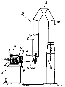
As seen in FIG. 1 a melt reduction furnace 1 for the
production of pig iron is associated with a tubular exhaust-gas
stack 3 for removal and cooling of the exhaust gases is attached
at the top part 2 of the furnace. The exhaust gas enters the
- 11 -
CA 02561827 2006-10-02
exhaust stack 3 with a temperature of about 1450EC and under a
gas overpressure of about 0.8 bar above atmospheric pressure.
A connecting duct 4 attached to the furnace 1 is cooled
by means of a cooling medium having a temperature Ti and coming
from a supply 16. In the example, this cooling medium a.s boiling
water and is fed to the exhaust stack 3 at a temperature Ti of
260EC. The cooling medium moves through cooling pipes 9 of the
exhaust stack 3. The pipes 9 in the example form the primary
wall of the exhaust stack 3.
According to the invention, a top part 2 of the furnace
1 where the connecting duct 4 is attached is also cooled with a
cooling medium of the same temperature Ti as the cooling medium
for cooling the exhaust stack 3. In the example, the cooling
medium for cooling the top part 2 of the furnace 1 thus also has
a temperature of 260EC. This temperature Ti refers to the
cooling medium fed to the furnace 1. The cooling medium in the
top part 2 of the furnace 1 moves through cooling pipes 10 of the
furnace 1, and these cooling pipes 10 are provided at the inside
wall of the furnace 1 of the top part 2 in the example. The
cooling pipes 10 are here coiled into a cooling jacket 11.
According to a preferred embodiment of the invention, the cooling
jacket 11 consists of a plurality of cooling jacket sections in a
way that is not shown in further detail, and these may be
separately connected and disconnected. It is within the scope of
the invention that boiling water is likewise used for cooling the
top part 2 of the furnace 1. Evaporative cooling for the furnace
- 12 -
CA 02561827 2006-10-02
1 produces significant advantages, as already explained more
extensively above. According to an embodiment of the invention,
parts of the lower furnace section may also be cooled in the same
way as the top part of the furnace.
In the example according to FIGS. 1 to 3, the furnace 1
has at its top part 2 a connecting collar 12 that is provided for
attaching the exhaust stack 3 or connecting duct 4. According to
the invention this connecting collar 12 is cooled with the
cooling medium also used for cooling the top part 2 of the
furnace 1. In other words, the cooling medium for the furnace 1
is conducted through cooling pipes 10 provided both at the inside
wall of the furnace 1 and at the inside wall of the connecting
collar 12. Hence, the cooling medium for the connecting collar
12 likewise involves preferably boiling water at the temperature
Ti.
FIGS. 2 and 3 show the attachment of the exhaust stack
3 and the connecting duct 4 to the connecting collar 12 of the
furnace 1. The connecting duct 4 is fitted coaxially into the
connecting collar 12 and fastened to the connecting collar 12.
The cooling pipes 9 form the primary wall of the connecting duct
4. The cooling pipes 10 form the primary wall of the connecting
collar 12. The cooling pipes 9 and 10 both advantageously carry
boiling water with a temperature Ti of 260EC as the cooling
medium. As already described above, relative thermal expansion
between furnace 1 or connecting collar 12 and exhaust stack 3 may
- 13 -
CA 02561827 2006-10-02
be effectively avoided in this way. Both the connecting duct 4
and the connecting collar 12 have an outside insulation layer 13.
Preferably as shown in the example, the cooling pipes
provided at the inside wall of the top part 2 of the furnace 1
extend from this inside wall into the connecting collar 12 and
overlay the pipes 10 lining the furnace top 1 and collar 12. The
cooling pipes 10 are therefore coiled not just for the cooling
jacket 11 in furnace 1, but also, as it were, into the connecting
collar 12. In other words, the cooling pipes 10 for cooling the
furnace 1 extend into connecting collar 12, as well. This is
explained in more detail below based on a special embodiment.
It can also be seen in FIG. 1 that the exhaust stack 3
is supported on a floor 17 by support elements or vertical
supports 8. The vertical supports 6 are preferably heated with a
medium, as is the case in the example, and this medium for the
vertical supports 8 comes from the supply 16 and has the same
temperature Ti as the cooling medium for the exhaust stack 3 and
as the cooling medium for the furnace 1 or connecting collar 12.
Hence, in the example, the medium for heating the vertical
supports 8 also has the temperature Ti of 260EC. The medium for
the vertical supports 8 likewise involves preferably boiling
water. For this purpose, the vertical supports 8 are hollow,, for
example pipes, through which the medium flows. By heating the
vertical supports 8, relative thermal expansion of the connecting
ducts 4 and the posts 8 may effectively be avoided, so that no
related stresses are produced. This entails the considerable
- 14 -
CA 02561827 2006-10-02
advantage of eliminating the need for compensators between the
individual sections of the exhaust stack 3 to take up thermal
expansion. The vertical supports 8 are supported at the bottom
on one single load uptake surface 17. Since both the top part 2
of the furnace 1 and the connecting collar 12, as well as the
exhaust stack 3 are cooled with a cooling medium of the same
temperature Ti, the above-mentioned load uptake surface for the
supporting elements may be defined in a very simple and accurate
way. The supporting elements or the vertical supports 8
according to the preferred embodiment and in the example
according to FIG. 1 are formed are pivoted at their upper and
lower ends, that is each vertical support 8 is attached via a
hinge joint to the exhaust stack 3, and preferably via a hinge
joint to the floor 17. This has the advantage that horizontal
thermal expansions may likewise be absorbed or compensated
without any problems.
FIG. 1 furthermore shows that the exhaust stack 3 has
the above-mentioned horizontal or slightly inclined connecting
duct 4 that continues into a first vertical connecting duct or
stack section 5 in which the exhaust gas is conducted upward.
This first vertical exhaust stack section 5 is connected to a
downwardly U-shaped baffle section 6 that in turn is connected to
a second vertical stack section 7, in which the exhaust gas moves
downward. In FIG. 1, the further treatment of exhaust gas after
the exhaust stack 3 is not shown. The cooled exhaust gas in the
- 15 -
CA 02561827 2006-10-02
exhaust stack 3 may, for instance, serve to preheat ore for the
production of steel.
In the example according to FIGS. 4 and 5, two adjacent
collars 12 and 14 are provided at the top part 2 of furnace 1.
In the example, the angle between these two collars 12, 14 as
measured between the center lines or axes of the collars 12 and
14 is 80E. This angle is chosen as small as possible in order
to make the system as compact as possible. In similar prior-art
systems, this makes the very narrow space between collars 12 and
14 impossible to cool. The invention is based on the knowledge
that efficient cooling of this narrow space or inside wall
section 15 of the furnace is essential for long-term and
functionally reliable operation of the device. According to the
invention efficient cooling of the inside wall section 15 of the
furnace between both collars 12 and 14 is made possible as shown
a.n FIG. 5 in that the cooling pipes 10 that are coiled into a
cooling jacket 11 of the furnace 1 initially extend to the right
side along the inside wall of furnace 1. These cooling pipes
then pass as coils into the first connecting collar 12, whereupon
on the left side of the first connecting collar 12, the cooling
pipes again pass out of this connecting collar 12, and then over
the narrow inside wall section 15 of the furnace. This ensures
very efficient cooling of the inside furnace wall section 15.
The cooling pipes 10 on the left side of the inside wall section
15 of the furnace then pass out as coils into the second
connecting collar 14, and on the left side of this second
- 16 -
CA 02561827 2006-10-02
connecting collar 14, they again pass out of the connecting
collar 14 and further along the inside wall of furnace 1.
Guiding the cooling pipes 10 in this way is possible, since the
invention uses evaporative cooling, and because evaporative
cooling allows cooling pipes 10 of a very small diameter, so that
the cooling pipes 10 may also have very small bend radii,
enabling them to be fitted to this complex shape between the two
collars 12 and 14.
- 17 -