Note : Les descriptions sont présentées dans la langue officielle dans laquelle elles ont été soumises.
CA 02562930 2006-09-26
1
SHELF SYSTEM
FOR STORING AND ARCHIVING OBJECTS
Description
The invention concerns a shelf system for storage and archiv-
ing of objects, consisting of at least one shelf with a rec-
tangular plan view, on the corners of which vertical columns
with a T-section are arranged, whereat between each two end
to columns horizontal, pocket-like traverses for the support of
shelves can be mounted, which can be clamped between the trav-
erse and its supporting column of the shelf system by lifting
the shelf, and the column having reliefs arranged in a grid
pattern to retain the downward pointing pairs of hooks of the
i5 traverses as well as slot-like recesses arranged in a grid
pattern to retain additional shelf system components.
A large number of shelves and shelf systems are known, the in-
dividual parts of which, such as columns, side ladders or
2o traverses and shelves are interconnected with various methods
of attachment. As a rule, such shelf systems have several col-
umns at the corner points of the shelf systems, where at cer-
tain vertical distances one or more horizontal shelves are at-
tached, on which objects or bulk goods are stored.
The disadvantage of such shelves or shelf systems is that
these, depending on the type of connection used, such as weld-
ing or bonding, can no longer be disassembled or adapted to
the needs of the user. Therefore, while these shelves or shelf
~o systems provide a high level of stability, a variation in size
and number of shelves in the shelf system is severely limited.
Further to that, these shelves or shelf systems are difficult
to transport due to their fixed connections and required
space.
CA 02562930 2006-09-26
2
In addition, a large number of peg systems for shelf systems
are known, where the shelf system components, such as shelves,
columns, traverses etc., are connected, for example, but
tongue and groove connections. In some systems the shelves
simply rest on webs or pins at the traverses. However, this
results in a high level of instability of the shelf systems.
Shelf systems that are screwed together or assembled with spe-
cial connecting elements require considerable effort for as-
io sembly or disassembly, creating a challenge for the persons
required to do the job. Further to that, connecting elements
with complicated designs are frequently required to connect
the shelves, posing production-related problems.
is From DE 101 98 179 A1 and DE 101 60 369 A1 a shelf system is
~;nov~n, consisting of at least one shelf system, in which
poc~:et-like traverses for the attachment of shelves are
mounted between two end columns. The columns are quipped with
reliefs to retain vertically and horizontally distanced, down-
zo ward pointing pairs of hooks at the traverses. Here, one down-
ward pointing end bracket of the shelf is pressed in between
the traverses and the columns of the shelf system supporting
these, clamping them tight against lifting of the shelves.
Aside from shelves, suspended parts can also be mounted in the
retaining pockets of the traverse in self-clamping fashion.
In this way, a shelf system is realized that can be completely
assembled without the necessity of welded, screwed or similar
connections and is easy to assemble. In spite of this, the
~r shelf system is not stable enough for all application cases.
For example, in case of very high, very wide or very deep
shelf systems, or if the shelf systems is loaded with very
heavy objects to be stored, particularly in industrial appli-
cations, the shelf system becomes increasingly unstable. Fur-
CA 02562930 2006-09-26
3
thermore, there is a lack of means for storing specific ob
jects, such as vehicle tires, hanging files and other large
and heavy and/or bulky objects requiring special holders or
supporting parts on the shelf system. Thus, the variety for
s storage of objects is limited.
Further to that, from FR 2,725,350 A1 a shelf system is known,
in which the traverses are formed as U-profiles. In these,
maintaining certain distances, several horizontal long=tudinal
to braces are inserted. In addition, the side surfaces of the
center leg of each column have grid-like arranged reliefs to
retain the downward pointing pairs of hooks of the U-profile
traverses.
m. Therefore, it has been the objective of the invention to cre-
ate a shelf system of the above described type for storing and
archiving of objects, which guarantees high stability and load
capacity while still allowing a wide variety of stored objects
of unvarying kinds with regard to size, shape and weight.
P.ccording to the invention, this problem is solved by
- an insert node and/or stabilizing profile equipped with a
hook, which can be inserted in the slot-like recesses of
the column for the attachment with connecting braces,
2s - an angle plate that can be inserted in and attached to the
column for the connection witn the base,
- a pair of interconnectable spacer angles for the connec-
tion of several shelf systems and/or for the connection to
the base, and
'o - a suspension insertable in the traverse to support a hang-
ing rail for hanging files or similar items.
In the sense of the invention, base is to be understood as
floor, wall or ceiling of a room and in certain cases may also
CA 02562930 2006-09-26
4
refer to the column of the shelf system.
The hooks of the insert nodes or stabilizing profiles are sim-
ply inserted in the slot-like recesses of the column and con-
s nected to further braces, e.g. cross braces or diagonal
braces. These braces, on the one hand, may serve to stabilize
the shelf system and, on the other hand, be used for storage
of large, bulky objects resting against the braces and are
supported by them. Depending on the design of the insert nodes
io or stabilizing profiles. they may also be used for the purpose
of connecting tsro adjacent shelf systems of the same type,
which are then stabilizing each other. In addition, the braces
connected to the insert nodes or stabilizing profiles provide
a wide variety of arrangement possibilities for the storage of
is objects, in particular heavy, large and bulky objects, such
as, for example, are stored in large industrial warehouses,
e.g. automobile parts in the automobile industry.
The angle plate that can be inserted or attached to the side
~o of the column serves, on the one hand, as a foot for the col-
umn of the shelf system and, on the other hand, can be used as
an overhead attachment on the upper end of the column to a
base, such as the ceiling of the room. This stabilizes the
shelf system and fixes it in place and secures it against tip
2s ping over.
Another means of stabilizing the shelf system consists in that
one spacer angle at the column of a shelf system and another
spacer angle at the column of an adjacent shelf system are
3n connected as well as both spacer angles are connected to each
other with screws. Another possibility is that the second
spacer angle is attached to a base, e.g. the wall of a room.
The pair of spacer angles also permits, if desired, the reali-
zation of uneven distances between adjacent shelf systems, re-
CA 02562930 2006-09-26
spectively their distances from the walls of the room. Thus,
the pair of spacer angles provides a stabilizing function as
well as helping to locate the shelf system within the room,
therefore er:traordinarily enhancing their load bearing capa
s bility.
The suspension for a hanging rail, in particular for hanging
files, folders, pockets etc. for hanging registers for use in
offices and archives considerably expands the variety of stor-
~o age possibilities and utilization of the shelf system. The
suspension of the hanging rail is simply inserted in the
pocket-like traverse, where it is held securely.
P~Iounting and attachment of the insert nodes, stabilizing pro-
m files, angle plate and interconnectable spacer angle using the
grid-pGttern cutouts, reliefs and slots of the column in con-
nection with traverses mounted grid-like on the column results
in a complex shelf system which is stable, able to carry heavy
loads and extremely versatile. In addition, all of these com-
ao penents are designed as single parts and thus can be manufac-
tured simply and cost effectively, since they only have to be
punched out and bent.
In accordance with another embodiment of the invention, the
insert node and the stabilizing profile are designed as a T-
stoaped, left or right pointing or cross-shaped Sheet metal
profile, whereat a pair of hooks is provided at least on one
leg and the other leg is equipped with at least one perfora-
tion.
The left or right pointing insert nodes and stabilizing pro-
files serve the purpose of attaching additional braces to a
shelf system or to an adjacent shelf system. The leg of the
insert node or stabilizing profile provided with at least one
CA 02562930 2006-09-26
6
pair of hooks is simply suspended from the corresponding slots
at the column. The other leg projects from the column and
serves to receive and attach a brace. The component designed
as a cross-shaped sheet metal profile may also be used for the
connection of an adjacent shelf system. A continuous leg, as
described above, is inserted in the column and additional
braces are attached to the two remaining parts of the cross
legs. In this may, one column of the adjacent shelf system can
be omitted, since its additional braces are connected to the
io insert node or stabilizing profile.
Further to that, the hooks at the insert node and the stabi-
lizing profile are arranged in a grid-like pattern in vertical
and/or horizontal alignment to each other. The grid-like
Is alignment of the hooks or pairs of hooks corresponds with the
grid-like arranged slots of the column, so that a vertical
and/or horizontal arrangement of the hooks at the insert node
and the stabilizing profile is possible.
~o In order to design the insert node or the stabilizing profile
itself with sufficient stability and load bearing capacity for
the braces to be attached, the longitudinal sides of the leg
of the insert nodes and stabilizing profiles may be designed
with a canted edge, so that the cross-section of the legs form
a~ a U-profile which clamps the brace as well as the column to-
gether.
Further to that, the legs of the insert nodes and the stabi-
lizing profiles may be equipped with additional means of ar-
3o resting to engage in the column and/or the connecting braces.
Such additional means of arresting may be in form of naps,
beads, creases, bumps, recesses etc. which engage in corre-
sponding opposite means of arresting at the column and/or con-
CA 02562930 2006-09-26
necting braces. These means of arresting provide further sta-
bilization of the shelf system.
In a further advantageous embodiment of the shelf system ac-
s cording to the invention, the angle plate consists of a base
plate and a perpendicular web, which can be inserted in the
hollow profile at the open end of the column with T-shaped
cross-section and fixed in place with screws. Thus, the up-
right web is inserted into the hollow space resulting from
io cross beam of the T-profile. This web, that is equipped with
at least one perforation, is attached with screws to the col-
umn, i~rhich also has grid-like aligned perforations on opposite
longitudinal sides.
is Further to that, the base plate of the angle plate can be con-
nected to the floor or ceiling of the room in order to fix the
shelf system in place.
In a further embodiment of the solution according to the in-
2~ vention, the spacer angle legs are preferably provided with
different lengths, in 4ahich at least one perforation is pre-
sent, whereat the perforation of one spacer angles matches
that of the other spacer angle. The difference in length o the
legs of the spacer angles allows a variable distance between
2s the shelf systems or in relation to the base, e.g. the wall of
a room, since the spacer angles, due to their matching, grid
like perforations can be screwed to each other in various dif
ferent ways, depending on locally existing circumstances.
Here, the perforations ma preferably consists of boreholes or
3o elongated holes.
In order to realize a suspension for the hanging rail, this
consists of a sheet metal plate having at least one projection
to retain the hanging rail. The number of projections protrud-
CA 02562930 2006-09-26
8
ing from the sheet metal plate depends on the type of hanging
rail. For example, the hanging rail may be designed with a
single track or double track and have a cross-section that de-
termines the number and shape of projections at the suspen-
sion. The free end of the hanging rail is simply placed onto
the corresponding projections of the suspension until it is
flush with the sheet metal plate.
For the stabilization of the suspension for the hanging rail,
io the side ends of the sheet metal plate of the suspension may
be formed into protruding bracket that lie flat against the
column.
The shelf system is preferably designed in a creating grid
is pattern which determines the width, height and depth of the
shelf system, but also the distances between the pairs of
hooks, the perforations and arresting means of the traverses
and other attaching parts and corresponding receptacle cut
outs, perforations and slot-like recesses in the column, re
~o sulting in an overall coherent shelf system concept.
It is understood that the above described and in the following
explained characteristics can be used not only in the respec-
tive described combination, but also in other combinations or
~s as a stand-alone design, without leaving the scope of the pre-
sent invention.
The idea on which the invention is based is explained in
greater detail in the following description with the aid of
application examples represented in drawings. The individual
figures show:
CA 02562930 2006-09-26
9
Fig. 1 a perspective view of a shelf system in the basic
form of the shelf system in accordance with the
in-
vention,
Fig. 2 a partial front view II of a column of the shelf
s system according to Fig. l,
Fig. 3 a side view of the column according to Fig. 2,
Fig. 4 a rear view of the column according to Fig. 2,
Fig. 5 a cross-section view along the line V-V of the
col-
umn according to Fig. 9,
iu Fig.6 a perspective side view of a shelf for a shelf
sys-
tem according to Fig. l,
Fig. 7 a perspective end view of a shelf according to
Fig.
6,
Fig. 8 a schematic side view of a traverse for a shelf
is system according to Fig. 1,
Fig. 9 a schematic side view of the traverse a~~cording
to
Fig. 8 with installed shelf,
Fig. 10 a schematic side view of the traverse according
to
Fig. 9 with installed shelf and attachment on
a
zo column,
Fig. 11 a front view of the traverse according to Fig.
8,
Fig. 12 a front view of an insert node in a first design
shape,
Fig. 13 a front vievr of an insert node in another design
shape,
Fig. 14 a side view of the insert node according to Fig.
13,
Fig. 15 a front view of the insert node according to Fig.
13 with attachment on a column and attached brace,
3u Fig.16 a front view of a stabilizing profiles,
Fig. 17 a perspective partial view of a stabilizing profile
according to Fig. 16,
Fig. 18 a front view of a suspension for a hanging rail,
CA 02562930 2006-09-26
Fig. 19 a side view of a suspension for a hanging rail
ac-
cording to Fig. 18,
Fig. 20 a side view of a traverse with installed suspension
according to Fig. 19 with attached hanging rail,
s Fig. 21 ea front view of a spacer angle,
Fig. 22 a side view of a spacer angle according to Fig.
21,
Fig. 23 a plan view of a spacer angle according to Fig.
21
with attachment on a column,
Fig. 29 26 schematic views of application examples of
- a
io pair of interconnectable spacers,
Fig. 27 a side view of an angle plate,
Fig. 28 a plan view of an angle plate according to Fig.
27,
Fig. 29 a front view of an angle plate that can be inserted
in a column, and
Is Fig. 30 a plan view of two angle plated on top of each
other in connection with two columns.
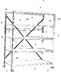
Fig. 1 shows a shelf 1 of a shelf system having a rectangular
plan view and preferably being made completely from sheet
2o metal. At each corner of shelf 1 there is a vertical column 2
with a foot 3 on its lower end. The two rear columns 2 are in-
terconnected by two diagonal braces 4 crossing each other,
thus providing longitudinal stability to shelf 1.
~s Further to that, the respective pairs of columns 2 at each end
are interconnected by several horizontal shelves S at certain
distances to each other, on which object of any kind are
stored (objects not shown). The upper shelf 5 acts as a top
cover shelf, while the bottom shelf is installed at a certain
3o distance from the floor.
figs. 2 to 5 show enlarged views of area II according to Fig.
1 of a column 2. This exhibits at its front according to Fig.
2 pairs of recesses 6 at certain distances to one another,
CA 02562930 2006-09-26
11
which are designed in the shape of slots 7. Suspended parts
(not shown) can be inserted in he slots 7, for example, cover
panels or special holders for certain stored objects, etc. In
addition, interspaced perforations 8 are provided. At the rear
s side of the column 2 according to Fig. 4, further perforations
or boreholes 9 are provided, which line up with the perfora-
tions 8 at the front side of the column 2. These perforations
8 and boreholes 9 can be used for the attachment of random
parts with of screws and/or to attach the column 2 on a wall.
io
Further to that, the column 2 is equipped with a number of
interspaced reliefs 10, which are essentially intended to re-
duce weight of the columns 2 by reducing the material volume
as well as to act as receptacles for other parts to be de-
scribed later. The slots 7, the perforations 8, the boreholes
9 and the reliefs 10 are arranged on the column 2 in a grid
pattern.
Furthermore, as shown in Figs. 4 and 5, the column 2 is de-
z,~ signed as a rolled hollov.~ profile made from band steel, so
that the finished column 2 has a gap 11 at its rear side.
Thus, the cross-section of the column 2 essentially has the
shape of a T according to Fig. 5.
~s Fig.6 shows a perspective side 7 a perspective
view and Fig.
end view of shelf 5. Each of longitudinalsides has down-
its
ward protruding a side wall 12t.The bottom free end of
the
side v.~all 12 has a trough-shapedcanted edge 13, as shown
in
Fig. 7.
A do~r~nward protruding end bracket 19 is attached to each end
of shelf, which is intended to fix the end of the shelf by
clamping it between the columns 2 of shelf 1 and the traverses
15.
CA 02562930 2006-09-26
12
Figs. 9 to 11 show various view of a traverse 15 for a shelf
1, which are inserted between two columns 2, which are ar-
ranged at the end of shelf 1.
s
A basic component 16 with an upper horizontal support edge 17,
on which the underside of shelf 5 is resting when installed,
is attached to traverse 15.
to Each end of traverse 15 is equipped with a pair of hooks 18 at
a vertical distance to each other, as shown in Fig. 11. The
hooks 18 engage in the reliefs 10 of column 2 of shelf 1 ac-
cording to Fig. 11. In this way, the end bracket 15 of shelf 5
is securely clamped in place between traverse 15 and column 2.
The insert node 19 shown in Fig. 12 has two legs, i.e. one
horizontal leg 21 branches off on either side of the vertical
leg 20. In contrast, the insert node 19 shown in Figs. 13 and
14 in a front and side view has only one leg. Thus, the insert
~o node 19 is designed as a cross-shaped left- or right-hand
sheet metal profile. Fig. 13 illustrates the right-hand insert
node 19. The left-hand insert node 19 corresponds to a mirror
image of the right-hand insert node 19. The vertical leg 20 of
the insert nodes have a pair of hooks 22 located in cutouts
2s 23. Within a pair of hooks 22, these may be aligned in line
4aith each other according to Fig. 12 or offset to each other
according to Fig. 13, since they engage in pairs in the corre
spondingly spaced pairs of recesses 6 of column 2, as shown in
Fig. 15, whereat the arrangement of hooks 22 corresponds to
3o the grid-like pattern of recesses 6.
The longitudinal sides of legs 20 and 21 of the insert nodes
19 are equipped with canted edges 26 to retain the connecting
braces 25. Several circular boreholes or elongated holes 24
CA 02562930 2006-09-26
13
are provided on the horizontal legs 21 and on leg 20 of insert
node 19, which serve the purpose of attaching the connecting
braces 25, for example, by means of screw connections, to in-
sert node 19. Further to that, the legs 20 and 21 are provided
s with nap-like arresting means 27, which engages in correspond-
ing counterparts (not shown) in braces 25 and/or column 2, in
order to obtain increased positional stability of the insert
nodes 19.
to The stabilizing profile 28 according to Figs. 16 and 17 is de-
signed similarly to insert node 19. The stabilizing profile 28
consists of an angle profile and has a U-shaped cross-section.
In the are of the corner the stabilizing profile 28 has a
semicircular recess 29, which is lined up with a perforation 8
is of column 2. By means of a screw (not shown) and a special
canted washer, it is possible to additionally screw the stabi-
lizing profile 28 to column 2, after the pair of hocks 22 has
engaged in the corresponding recesses 6 of column 2.
2~~~ Figs. 18 to 20 show a suspension 30 for a two-track hanging
rail 31 for hanging office files and similar items. The hang
ing rail 31 is indicated in dashed lines in Figs. 18 and 20.
The suspension 30 is insertable in traverse 15 which, in turn,
as already described, is inserted in column 2, as shown in
zs Fig. 20.
Furthermore, suspension 30 for the hanging rail 31 consists of
a sheet metal plate and is equipped with two projections 32,
which are formed by bending them out of the plate, to retain
~o one end of the hanging rail 31. The oblique arrangement of the
projections 32 to each other results frorn the shape of the
hanging rail 31. In addition, at the ends of the sheet metal
plate of suspension 30 there are protruding brackets 35 to
rest against two spaced columns 2.
CA 02562930 2006-09-26
19
Figs. 21 to 23 show a spacer angle 34 with two legs 35 and 36
running perpendicular to each other and are of different
lengths. Two of these spacer angles 39 are connected to each
s other, e.g. by screws and nuts, as schematically shown Figs.
24 to 26. A pair of interconnected spacer angles 34 serves the
purpose of connecting several shelf systems 1 or to connect to
a base 37, e.g. the wall of a room. For that purpose, the legs
35 and 36 of the spacer angle 34 are provided with circular
to and elongated holes 24 in a grid pattern matching the perfora-
tions 8 of the column 2. For this purpose, the perforation 24
of one spacer angle 39 is in line with that of the other
spacer angle 34.
is figs. 24 to 26 show a number of possible applications of a
pair of interconnectable spacer angles 34 with a base 37
and/or shelf systems l, whereat the legs 35 and 36 of differ-
ent lengths can be interconnected in several different ways.
2o Figs. 27 to 29 show an angle plate 38 that can be inserted in
the column 2 of a shelf 1. This angle plate 38 is inserted at
the side of column 2 and attached to said column and serves
the purpose of connecting to a base 37, for example, to the
floor or ceiling of a room, in order to stabilize the shelf 1
2s and fix it in place.
Angle plate 38 consists of a base plate 39 and a web 40 per-
pendicularly protruding from it, so that the web stands at a
right angle to base plate 39. Web 40 is provided with an elon-
3o gated perforation 24, which is lined up with an opening 8 in
column 2 in order to attach web 40 to cot mn 2 with screws.
Further to that, the lower section of the web 90, where it is
attached to the base plate 39, is of narrower width. The base
plate 39 of angle plate 38 has 4 boreholes 41 in its corners,
CA 02562930 2006-09-26
which are executed in form of elongated holes and are provided
for the purpose of connecting to the floor or the ceiling of a
room.
It is also possible to join two such angle plates 38 in oppo-
site directions in such a way that their base plates 39 are
nearly aligned on top of each other and their upright webs 90
are positioned opposite each other forming a gap. This is made
possible by the narrower section of the web 40. In this way,
o~ it is possible, for example, to connect two adjacent columns
2, into which one of each of the webs 90 protrudes. For that
purpose, the overlapping base plates 39 are screwed to the
floor or ceiling of the room using their elongated holes 91.
Furthermore, the elongated perforations 24 in the upright webs
is 40 can be connected by screws to the perforations 8 of column
2.
CA 02562930 2006-09-26
16
Legend
1 Shelf system
2 Column
3 Foot
4 Brace
Shelf
6 Recess
7 Slot
8 Perforation
9 Borehole
Relief
11 Gap
12 Side wall
13 Canted edge
14 End bracket
Traverse
16 Basic component
17 Support edge
18 Hook
19 Insert node
Leg
21 Leg
22 Hook
23 Cutout
29 Perforation
Connecting brace
26 Canted edge
27 Arresting means
28 Stabilizing profile
29 Recess
Suspension
31 Hanging rail
32 Projection
33 Bracket
34 Spacer angle
Leg
36 Leg
37 Base
38 Angle plate
39 Base plate
4 0 Web
41 Borehole