Sélection de la langue

Search

Sommaire du brevet 2562995 

Énoncé de désistement de responsabilité concernant l'information provenant de tiers

Une partie des informations de ce site Web a été fournie par des sources externes. Le gouvernement du Canada n'assume aucune responsabilité concernant la précision, l'actualité ou la fiabilité des informations fournies par les sources externes. Les utilisateurs qui désirent employer cette information devraient consulter directement la source des informations. Le contenu fourni par les sources externes n'est pas assujetti aux exigences sur les langues officielles, la protection des renseignements personnels et l'accessibilité.

Disponibilité de l'Abrégé et des Revendications

L'apparition de différences dans le texte et l'image des Revendications et de l'Abrégé dépend du moment auquel le document est publié. Les textes des Revendications et de l'Abrégé sont affichés :

  • lorsque la demande peut être examinée par le public;
  • lorsque le brevet est émis (délivrance).
(12) Brevet: (11) CA 2562995
(54) Titre français: CHENILLE SANS FIN EN ELASTOMERE
(54) Titre anglais: ENDLESS ELASTOMERIC TRACK
Statut: Périmé et au-delà du délai pour l’annulation
Données bibliographiques
Abrégés

Abrégé français

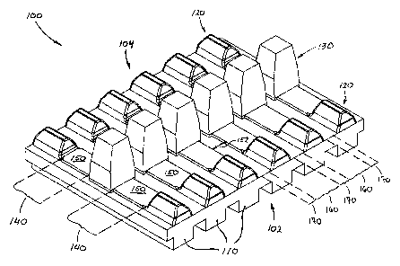
Cette invention porte généralement sur la configuration de la surface interne d'une bande de traction qui augmente la protection d'éléments de renfort intégrés sans réduire la flexibilité de la bande ou augmenter la production de chaleur. La surface extérieure de la bande comprend généralement une pluralité de tenons de traction alors que la surface intérieure comprend généralement une pluralité de tenons d'entraînement et/ou de guidage. Conformément à la présente invention, chaque groupe de tenons de traction, tenons d'entraînement et tenons de guidage, qui sont généralement alignés latéralement, définit généralement des zones de tenons non flexibles et chacune de ces zones de tenons est séparée par des zones de charnières généralement sans tenon. Les zones de tenons, sur la surface intérieure, comprennent également des projections situées entre les tenons d'entraînement et les tenons de guidage et le long des chemins de roues définis entre eux.


Abrégé anglais


This invention generally relates to the configuration of the inner surface of
a traction
band which increases the protection of the embedded reinforcing elements
without
reducing the flexibility of the band or increasing the generation of heat. The
outer surface
of the band generally comprises a plurality traction lugs while the inner
surface generally
comprises a plurality of drive and/or guide lugs. According to the present
invention, each
group of traction lugs, drive lugs and guide lugs, which are generally
laterally aligned,
defines generally non-flexible lug areas and each of these lug areas are
separated by
flexible and generally lug-less hinge areas. The lug areas, on the inner
surface thereof,
further comprise projections located between the drive lugs and the guide lugs
and along
the wheel paths defined therebetween.

Revendications

Note : Les revendications sont présentées dans la langue officielle dans laquelle elles ont été soumises.


Claims
1. A track for use on a tracked vehicle, said track being made of polymer and
adapted to travel over a sprocket wheel, a plurality of road wheels and an
idler
wheel, said track having an outer ground engaging surface and an inner wheel
engaging surface, said track comprising a plurality of substantially non-
flexible
lug areas separated by flexible lug-less hinge areas, each of said lug areas
comprising, on its outer surface thereof, at least one traction lug, and on
its inner
surface thereof, at least two drive lugs and at least one guide lug, said at
least two
drive lugs and said at least one guide lug being laterally spaced and defining
two
wheel paths, said lug areas having embedded therein reinforcing elements
aligned
with said drive lugs and said guide lugs, wherein said lug areas comprise
projections located in said wheel paths and above said reinforcing elements
such
that said wheel paths are thicker along said lug areas than along said lug-
less
hinge areas and such that said lug-less hinge areas are substantially devoid
of said
projections.
2. A track as claimed in claim 1, wherein one of said two wheel paths is
defined
between one of said at least two drive lugs and said at least one guide lug,
and
wherein the other of said two wheel paths is defined between the other of said
at
least two drive lugs and said at least one guide lug.
3. A track as claimed in claim 1, wherein projections on consecutive lug areas
define
a gap, and wherein said gap is being between 3% and 6% of a diameter of said
road wheels.
4. A track as claimed in claim 2, wherein projections on consecutive lug areas
define
a gap, and wherein said gap is being between 3% and 6% of a diameter of said
road wheels.
- 8 -

5. A track for use on a tracked vehicle, said track being made of polymer and
adapted to travel over a sprocket wheel, a plurality of road wheels and an
idler
wheel, said track having an outer ground engaging surface and an inner wheel
engaging surface, said track comprising a plurality of substantially non-
flexible
lug areas separated by flexible lug-less hinge areas, each of said lug areas
comprising, on its outer surface thereof, at least one traction lug, and on
its inner
surface thereof, two drive lugs and one guide lug laterally spaced to define
two
wheel paths, said lug areas having embedded therein reinforcing elements
aligned
with said drive lugs and said guide lugs, wherein said lug areas comprise
projections located in said wheel paths and above said reinforcing elements
such
that said wheel paths are thicker along said lug areas than along said lug-
less
hinge areas and such that said lug-less hinge areas are substantially devoid
of said
projections.
6. A track as claimed in claim 5, wherein projections on consecutive lug areas
define
a gap, and wherein said gap is being between 3% and 6% of a diameter of said
road wheels.
- 9 -

Description

Note : Les descriptions sont présentées dans la langue officielle dans laquelle elles ont été soumises.


CA 02562995 2013-03-28
File number : 4104-110
Revision : Amended for OA1
Date : 2013/03/28
Title of the Invention
[0001] Endless Elastomeric Track.
Cross-Reference to Related Applications
[0002] There are no cross-related applications.
Field of the Invention
[0003] The present invention generally relates to tracked vehicles which use
endless
tracks for propulsion. More particularly, the present invention relates to the
endless
tracks used on such tracked vehicles. Without being limitative in nature, the
present
invention particularly relates to endless tracks for use on heavy tracked
vehicles such as
military vehicles (e.g. tanks and transport vehicles) and heavy machinery
(e.g.
excavators, bulldozers, forestry equipments).
Background of the Invention
[0004] Conventionally, a military vehicle comprises a set of five or six road
wheels on
each side thereof over which a track or traction band runs. The suspension of
each wheels
is preferably independent. Along with the set of road wheels, the track system
also
comprises a sprocket wheel and an idler wheel, each of which are located at
each end of
the vehicle and are preferably located above the ground. More recently,
tracked military
vehicles, and other heavy tracked vehicles, have begun to use endless tracks
made of
rubber and/or other elastomeric material instead of metallic tracks.
[0005] In these recent track systems, the track generally comprises an outer
surface
comprising traction lugs and an inner surface comprising drive lugs and/or
guide lugs
(also referred to as guide horns). In these types of track, the drive lugs and
the guide
lugs, which are generally laterally spaced apart, generally define two or more
wheel paths
- 1 -

CA 02562995 2013-03-28
File number : 4104-110
Revision : Amended for OA1
Date : 2013/03/28
into which the road wheels are adapted to roll. In the majority of tracks, the
wheel paths
are generally flat and continuous in order to avoid undesirable vibrations.
[0006] Overtime, it has been discovered that the rubber of these tracks had a
tendency to
delaminate, particularly over the reinforcing elements embedded into the track
rubber
body and which are generally aligned with the lugs.
[0007] A general prior art solution for preventing delamination was to
increase the
overall thickness of the track. Yet, if this solution was possible for small
or relatively
thin tracks (e.g. snowmobile rubber tracks), for larger tracks, it is not
appropriate.
[0008] As a matter of fact, large traction bands used on large and/or heavy
vehicles are
generally already at their maximum possible thickness. Any overall increase of
thick
would bring unwanted results.
[0009] Indeed, when rubber and/or elastomeric material bends, the bending of
the
material generates heat. On small tracks, the heat generation is relatively
low and easily
dissipated due to the small volume to surface ratio. However, on larger
tracks, the heat
generation is substantially high and less easily dissipated due to the higher
volume to
surface ratio. Moreover, since the hinge portions or areas of large tracks
used on heavy
vehicles are generally already at their maximum possible thickness, any
addition of
material at the hinge areas would most probably fatally increase the heat
generation
above the threshold above which failure of the material are likely to occur,
thereby
creating other problems.
[0010] Despite that the hinge areas are already at their maximum thickness,
there is still a
need to improve the durability and/or resistance to wear of rubber and/or
elastomeric
tracks that are preferably but not exclusively used on heavy vehicles.
Objects of the Invention
- 2 -

CA 02562995 2013-03-28
File number :4104-110
Revision : Amended for OA I
Date : 2013/03/28
[0011] Accordingly, an aspect of the present invention is to provide an
endless track for
used on tracked vehicles which provides increased durability without hindering
the
flexibility of its hinge areas.
[0012] Another aspect of the present invention is to provide an endless track
which
increases the protection of the track reinforcing elements over the wheel path
in the lugs
areas.
[0013] Still another aspect of the present invention is to provide an endless
track which
generally does not substantially increase the level of vibration.
[0014] Other and further objects and advantages of the present invention will
be obvious
upon an understanding of the illustrative embodiments about to be described or
will be
indicated in the appended claims, and various advantages not referred to
herein will occur
to one skilled in the art upon employment of the invention in practice.
Summary of the Invention
[0015] Accordingly, the present invention consists of an endless track made of
rubber
[NOTE: As used hereinabove and hereinafter, the term "rubber" relates to any
elastic and
primarily non metallic materials such as rubber, elastomers, or other polymers
and/or
combinations thereof used in the manufacture of endless tracks]. The track
comprises an
outer surface onto which are disposed traction lugs for providing traction to
the vehicle.
The track also comprises an inner surface, itself comprising at least
outwardly projecting
drive lugs adapted to mate with a sprocket wheel and preferably further
comprising guide
lugs or horns adapted to guide the track over the road, idler and sprocket
wheels of the
vehicle. In order to provide a space for the wheels, the drive lugs and guide
lugs are
preferably laterally spaced apart along the width of the track. The spaces
between the
drive lugs and guide lugs define the wheel paths into which the wheels can
travel.
- 3 -

CA 02562995 2013-03-28
File number: 4104-110
Revision : Amended for 0A1
Date: 2013/03/28
[0016] According to an aspect of the invention, the drive lugs, guide lugs and
traction
lugs are preferably laterally aligned into generally non-flexible lug areas.
Consecutive lug
areas are separated by flexible hinge areas. The hinge areas allow the track
to bend as it
rotates around the wheels of the vehicle.
[0017] In order to provide enhanced durability of the track while not
hindering its
flexibility, the lug areas of the track of the present invention are further
provided with
projections on their inner surface located between the drive and guide lugs
and along the
wheel paths defined thereby. Consequently, the projections increase the
thickness of the
lug areas and more particularly along the wheel paths thereof, thereby further
protecting
the reinforcing elements embedded into the track.
[0018] Yet, the hinge areas are not provided with such projections and
therefore the
thickness of the hinge areas is not increased.
[0019] The track of the present invention understandably provides
discontinuous wheel
paths. Even though it might be believed that the track of the present
invention would
increase the noise level and/or the vibration level of the track, it is
generally not so. In
fact, in the present invention, the projections are dimensioned such that when
they
interact with large diameter wheels, only a small though generally
insignificant increase
of the sinusoidal movement is detected. Indeed, because of their configuration
and
dimension, the projections allow the road wheel to cross from a lug area to
the next
without rolling in the hinge area as in some prior art tracks, resulting in
only minimal
deformation of the track between consecutive lug areas. This results in wheel
paths
having a generally increased thickness over the embedded reinforcing
components,
giving them an increased protection from the environment. Moreover, the
resulting rise
in noise and vibration is negligible when compared to a conventionally
continuous wheel
path and the more so in the context of heavy tracked machinery.
Brief Description of the Drawings
- 4 -

CA 02562995 2013-03-28
File number :4104-110
Revision : Amended for OAI
Date : 2013/03/28
[0020] The invention may be best understood by reference to the following
detailed
description and considered in connection with the accompanying drawings
wherein:
[0021] Fig. 1 is a perspective view of the inner surface of a track according
to an
embodiment of the present invention;
[0022] Fig. 2 is a side view of the track of Fig. 1 with a road wheel over a
lug area;
[0023] Fig. 3 is a side view of the track shown in Fig.2 with the road wheel
over a lug
area and with a drive lug removed for clarity;
[0024] Fig. 4 is a perspective view of the track and road wheel shown in Fig.
2.
[0025] Fig. 5 is a side view of the track of Fig. 1 with a road wheel over a
hinge area;
[0026] Fig. 6 is a side view of the track shown in Fig.5 with the road wheel
over a hinge
area and with drive lugs removed for clarity;
[0027] Fig. 7 is a perspective view of the track and road wheel shown in Fig.
5.
Detailed Description of the Preferred Embodiment
[0028] As can be seen in Fig. 1, the track 100 of the present invention, which
is
preferably made of rubber and/or elastomeric material, comprises a plurality
of preferably
substantially non-flexible lug areas 160 separated by flexible hinge areas
170.
Understandably, the track 100 comprises an outer ground engaging surface 102
and an
inner wheels engaging surface 104.
[0029] The hinge areas 170 of the track are designed and dimensioned to be
flexible
enough to provide flexion between consecutive lug areas 160 yet thin enough
not to
generate excessive heat after numerous flexion. As it is known, excessive heat
generated
by successive flexions and extensions of the hinge areas 170 can have a
deleterious effect
to the track 100 and to the rubber thereof. Accordingly, in order to prevent
the generation
of excessive heat, the hinge areas 170 of the present track 100 are generally
limited in
their thickness.
[0030] The lug areas 160 of the track 100 are provided, on their outer surface
102, with
traction or terrain lugs 110. These traction lugs 110 are generally designed
to provide
- 5 -

CA 02562995 2013-03-28
File number: 4104-110
Revision : Amended for OA!
Date : 2013/03/28
friction between the ground and the track 100, thereby providing traction to
the vehicle
(not shown). Traction lugs 110 of different shape could be used according to
the terrain
upon which the track is intended to be used. The present invention is not
limited to any
types of traction lugs 110.
[0031] The inner surface 104 of the lug areas 160 are provided, in the
preferred
embodiment, with drive lugs 120, adapted to matingly cooperate with a sprocket
wheel
(not shown), and with at least one guide lug 130, adapted to guide the road
wheels of the
vehicle. As best shown in Fig. 1, the drives lugs 120 and the guide lug 130
are laterally
spaced apart in order to define paths 140 for the road wheels 200 of the
vehicle.
[0032] According to the present invention, in order to prevent or at least
slow down the
wear and/or delamination of the track 100, the space between the drives lugs
120 and the
guide lug 130 are provided with projections 150 slightly raised above the
inner surface of
the lug area 160. However, as clearly shown in Fig. 1, the hinge areas 170 are
not
provided with such projections 150. Understandably, the projections 150
increase the
thickness of the lug areas 160, more particularly along the wheel paths 140,
thereby
further protecting the reinforcing elements (not shown) embedded into the
track 100.
[0033] Even though these projections 150 create discontinuous or non-flat
wheel paths
140 along the length of the track 100, the space 152 between two consecutives
projections 150 is so chosen as to be relatively small when compared to the
diameter and
thus, the perimeter of the road wheels 200. This is best shown in Figs. 5 to
7.
[0034] As can be seen in Figs. 5 to 7, in the preferred embodiment, since the
road wheel
diameter is preferably much greater than the gap 152 between consecutives
projections
150, the level of vibration of the track is not significantly increased. Still
in the preferred
embodiment, the gap 152 between two longitudinally consecutive projections is
between
3% and 6% of the diameter of a road wheel. However, other ratios are also
possible and
the invention is not so limited.
- 6 -

CA 02562995 2013-03-28
File number: 4104-110
[0035] Although preferred embodiments of the invention have been described in
detail
herein and illustrated in the accompanying figures, it is to be understood
that the
invention is not limited to these precise embodiments and that various changes
and
modifications may be effected.
- 7 -

Dessin représentatif
Une figure unique qui représente un dessin illustrant l'invention.
États administratifs

2024-08-01 : Dans le cadre de la transition vers les Brevets de nouvelle génération (BNG), la base de données sur les brevets canadiens (BDBC) contient désormais un Historique d'événement plus détaillé, qui reproduit le Journal des événements de notre nouvelle solution interne.

Veuillez noter que les événements débutant par « Inactive : » se réfèrent à des événements qui ne sont plus utilisés dans notre nouvelle solution interne.

Pour une meilleure compréhension de l'état de la demande ou brevet qui figure sur cette page, la rubrique Mise en garde , et les descriptions de Brevet , Historique d'événement , Taxes périodiques et Historique des paiements devraient être consultées.

Historique d'événement

Description Date
Représentant commun nommé 2019-10-30
Le délai pour l'annulation est expiré 2019-10-07
Lettre envoyée 2018-10-09
Exigences relatives à la nomination d'un agent - jugée conforme 2018-08-01
Exigences relatives à la révocation de la nomination d'un agent - jugée conforme 2018-08-01
Demande visant la révocation de la nomination d'un agent 2018-07-24
Demande visant la nomination d'un agent 2018-07-24
Accordé par délivrance 2013-11-26
Inactive : Page couverture publiée 2013-11-25
Préoctroi 2013-07-23
Inactive : Taxe finale reçue 2013-07-23
Un avis d'acceptation est envoyé 2013-07-08
Lettre envoyée 2013-07-08
month 2013-07-08
Un avis d'acceptation est envoyé 2013-07-08
Inactive : Approuvée aux fins d'acceptation (AFA) 2013-06-25
Modification reçue - modification volontaire 2013-03-28
Inactive : Dem. de l'examinateur par.30(2) Règles 2012-10-05
Lettre envoyée 2011-09-07
Exigences pour une requête d'examen - jugée conforme 2011-08-22
Toutes les exigences pour l'examen - jugée conforme 2011-08-22
Requête d'examen reçue 2011-08-22
Inactive : Lettre officielle 2009-03-24
Lettre envoyée 2008-06-17
Inactive : Page couverture publiée 2008-04-06
Demande publiée (accessible au public) 2008-04-06
Modification reçue - modification volontaire 2007-10-05
Lettre envoyée 2007-02-19
Inactive : CIB en 1re position 2007-02-02
Inactive : CIB attribuée 2007-02-02
Inactive : Transfert individuel 2007-01-16
Inactive : Lettre de courtoisie - Preuve 2006-11-14
Inactive : Certificat de dépôt - Sans RE (Anglais) 2006-11-07
Demande reçue - nationale ordinaire 2006-11-07

Historique d'abandonnement

Il n'y a pas d'historique d'abandonnement

Taxes périodiques

Le dernier paiement a été reçu le 2013-09-20

Avis : Si le paiement en totalité n'a pas été reçu au plus tard à la date indiquée, une taxe supplémentaire peut être imposée, soit une des taxes suivantes :

  • taxe de rétablissement ;
  • taxe pour paiement en souffrance ; ou
  • taxe additionnelle pour le renversement d'une péremption réputée.

Les taxes sur les brevets sont ajustées au 1er janvier de chaque année. Les montants ci-dessus sont les montants actuels s'ils sont reçus au plus tard le 31 décembre de l'année en cours.
Veuillez vous référer à la page web des taxes sur les brevets de l'OPIC pour voir tous les montants actuels des taxes.

Historique des taxes

Type de taxes Anniversaire Échéance Date payée
Taxe pour le dépôt - générale 2006-10-06
Enregistrement d'un document 2007-01-16
TM (demande, 2e anniv.) - générale 02 2008-10-06 2008-06-17
TM (demande, 3e anniv.) - générale 03 2009-10-06 2009-08-27
TM (demande, 4e anniv.) - générale 04 2010-10-06 2010-09-16
Requête d'examen - générale 2011-08-22
TM (demande, 5e anniv.) - générale 05 2011-10-06 2011-09-15
TM (demande, 6e anniv.) - générale 06 2012-10-09 2012-09-14
Taxe finale - générale 2013-07-23
TM (demande, 7e anniv.) - générale 07 2013-10-07 2013-09-20
TM (brevet, 8e anniv.) - générale 2014-10-06 2014-09-22
TM (brevet, 9e anniv.) - générale 2015-10-06 2015-09-30
TM (brevet, 10e anniv.) - générale 2016-10-06 2016-09-29
TM (brevet, 11e anniv.) - générale 2017-10-06 2017-10-02
Titulaires au dossier

Les titulaires actuels et antérieures au dossier sont affichés en ordre alphabétique.

Titulaires actuels au dossier
SOUCY INTERNATIONAL INC.
Titulaires antérieures au dossier
DANNY ROY
FRANCOIS DUQUETTE
REMI BRETON
Les propriétaires antérieurs qui ne figurent pas dans la liste des « Propriétaires au dossier » apparaîtront dans d'autres documents au dossier.
Documents

Pour visionner les fichiers sélectionnés, entrer le code reCAPTCHA :


Pour visualiser une image, cliquer sur un lien dans la colonne description du document (Temporairement non-disponible). Pour télécharger l'image (les images), cliquer l'une ou plusieurs cases à cocher dans la première colonne et ensuite cliquer sur le bouton "Télécharger sélection en format PDF (archive Zip)" ou le bouton "Télécharger sélection (en un fichier PDF fusionné)".

Liste des documents de brevet publiés et non publiés sur la BDBC .

Si vous avez des difficultés à accéder au contenu, veuillez communiquer avec le Centre de services à la clientèle au 1-866-997-1936, ou envoyer un courriel au Centre de service à la clientèle de l'OPIC.


Description du
Document 
Date
(yyyy-mm-dd) 
Nombre de pages   Taille de l'image (Ko) 
Description 2006-10-05 7 282
Abrégé 2006-10-05 1 22
Revendications 2006-10-05 1 20
Dessins 2006-10-05 7 248
Dessin représentatif 2008-03-10 1 22
Page couverture 2008-04-02 2 59
Dessins 2007-10-04 7 231
Description 2007-10-04 6 281
Abrégé 2007-10-04 1 21
Revendications 2007-10-04 1 20
Description 2013-03-27 7 265
Revendications 2013-03-27 2 64
Abrégé 2013-03-27 1 21
Page couverture 2013-10-22 1 54
Certificat de dépôt (anglais) 2006-11-06 1 158
Courtoisie - Certificat d'enregistrement (document(s) connexe(s)) 2007-02-18 1 105
Rappel de taxe de maintien due 2008-06-08 1 113
Rappel - requête d'examen 2011-06-06 1 120
Accusé de réception de la requête d'examen 2011-09-06 1 177
Avis du commissaire - Demande jugée acceptable 2013-07-07 1 163
Avis concernant la taxe de maintien 2018-11-19 1 181
Avis concernant la taxe de maintien 2018-11-19 1 180
Taxes 2011-09-14 1 156
Taxes 2012-09-13 1 155
Correspondance 2006-11-06 1 26
Correspondance 2008-07-13 1 16
Taxes 2008-06-16 1 34
Taxes 2008-06-16 1 35
Taxes 2008-06-16 1 33
Correspondance 2009-03-23 1 14
Taxes 2008-06-16 1 38
Correspondance 2009-03-09 2 61
Taxes 2009-08-26 1 200
Taxes 2010-09-15 1 201
Correspondance 2013-07-22 1 35
Taxes 2013-09-19 1 24
Taxes 2014-09-21 1 25
Taxes 2015-09-29 1 25
Taxes 2016-09-28 1 25
Paiement de taxe périodique 2017-10-01 1 25