Note : Les descriptions sont présentées dans la langue officielle dans laquelle elles ont été soumises.
CA 02563486 2006-10-31
VEHICLE LAMPS WITH GLARE CONTROL
Field of the Invention
This invention relates to lamp capsules for vehicle headlamps and, more
particularly,
to lamp capsules which produce low glare in vehicle headlamp applications.
Background of the Invention
to Vehicle headlamps commonly include a lamp capsule mounted in a reflector so
that
the light source is located at or near the focal point of the reflector. Light
emitted by the lamp
capsule is directed in a forward direction by the reflector. The lamp capsule
typically includes
a high beam filament from which light is directed horizontally in a high beam
pattern and a
low beam filament from which light is directed below horizontal in a low beam
pattern. One
15 of the problems involved in the design and construction of vehicle
headlamps is to minimize
uncontrolled light emission outside the desired beam patterns, particularly
the low beam
pattern, that may impair the ability of oncoming drivers to see the road and
other vehicles.
This uncontrolled light is known as glare.
The typical low beam pattern requires that little or no light be projected
above the
2o horizontal plane and requires the maximum hot spot to be projected just
below the horizontal
plane. Factors such as filament size and internal and external uncontrolled
reflections cause
the source pattern to be spread, making a sharp transition line at the
horizontal plane difficult
to achieve. One approach is to aim the low beam pattern slightly lower than
horizontal. This
reduces glare for oncoming drivers but at the expense of reducing desired
illumination far
2s down the road. Another approach is to block undesired light. However, any
blockage reduces
the total illumination produced by the lamp and thereby reduces the
effectiveness of the lamp.
There is therefore a need to improve the low beam pattern and in particular to
sharpen the
transition line at the horizontal plane, while minimizing the adverse impact
on the total
illumination.
3o In a two-filament lamp capsule, light from the low beam filament falls on
the high
beam filament at close range, causing it to appear as if the high beam
filament were
illuminated at low
CA 02563486 2006-10-31
-2-
level in the direction of the low beam filament. Regions not facing the low
beam
filament remain dark. Light reflected from the high beam filament is then
projected onto
the reflector and into the field of view. The light reflected from the high
beam filament is
projected by the reflector as if the high beam filament were partially
illuminated and
produces a ghost image of the high beam filament. Thus, light is projected
above the
horizontal plane into the region that should not receive light when the low
beam filament
is illuminated. It is desirable to reduce or eliminate this ghost image of the
high beam
filament during low beam operation without substantially affecting lamp
intensity during
high beam operation.
Vehicle headlamps include a filament support structure which supports the high
beam and low beam filaments in desired positions in the lamp capsule and which
conducts electrical energy to the filaments. The filament support structure
typically
includes conductive support leads having sufficient rigidity to support the
filaments
under all expected environmental conditions. The filament support structure
should be
configured to limit blockage of light emitted by the filaments and to limit
stray
reflections that would adversely affect the beam pattern. Furthermore, the
positions of
the filaments in the lamp envelope and relative to each other have a
significant impact on
the beam pattern and on the overall performance and flexibility of the lamp
capsule.
Summary of the Invention
The lamp capsule is disclosed which comprises a lamp envelope including a
tubular portion, a dome closing one end of the tubular portion and a seal
closing the other
end of the tubular portion, a first filament mounted in the lamp envelope for
emitting
light when energized by electrical energy, a second filament mounted in the
lamp
envelope in spaced relation to the first filament for emitting light when
energized by
electrical energy, and conductors for supplying electrical energy through the
lamp
envelope to the first and second filaments. The lamp capsule further comprises
at least
one light-attenuating axial stripe on the lamp envelope. The axial stripe is
positioned on
the lamp envelope for blocking light emitted by the first filament and
reflected by the
second filament.
Preferably, the first filament is mounted on or near a central axis of the
lamp
CA 02563486 2006-10-31
-3-
envelope and the second filament is spaced from the central axis. The lamp
capsule may
include first and second spaced-apart axial stripes that are parallel to the
central axis of
the lamp envelope. The first and second axial stripes may be equally spaced
from a plane
containing the first and second filaments. In one embodiment, the first and
second axial
stripes are spaced apart by about the projected diameter of the second
filament on the
lamp envelope. The first and second stripes may have widths that are
approximately
equal to the diameter of the second filament.
The lamp capsule may further comprise a light-attenuating ring on the lamp
envelope adjacent to the seal for defining a lower boundary of a clear region
of the lamp
envelope. The lamp capsule may further comprise a light-attenuating layer on
the dome
and a light-attenuating ring on the lamp envelope adjacent to the light-
attenuating layer
for defining an upper boundary of the clear region.
A vehicle headlamp is also disclosed which comprises a reflector having a
focal point, a lamp capsule and a lamp base for mounting the lamp capsule in
the
reflector. The lamp capsule comprises a lamp envelope, including a tubular
portion and a
dome closing one end of the tubular portion, first and second filaments
mounted in the
lamp envelope in spaced relationship for emitting light when energized by
electrical
energy, and at least one light-attenuating axial stripe on the lamp envelope.
The axial
stripe is positioned on the lamp envelope for blocking light, emitted by the
first filament
and reflected by the second filament, which would be reflected by the
reflector above
horizontal when the vehicle headlamp is mounted in a vehicle.
A lamp capsule is also disclosed comprising a lamp envelope including a
tubular portion and a dome closing one end of the tubular portion, the lamp
envelope
having a central axis; first and second filaments mounted in the lamp envelope
in
spaced relationship for emitting light when energized by electrical energy;
first and
second spaced apart light-attenuating axial stripes on the lamp envelope, the
first and
second axial stripes equally spaced from a plane containing the first and
second
filaments for blocking light emitted by the first filament and reflected by
the second
filament when the second filament is deenergized; and conductors for supplying
electrical energy through the lamp envelope to the first and second filaments.
According to one aspect of the invention, there is provided a lamp capsule
comprising: a lamp envelope including a tubular portion, a dome closing one
end of the
CA 02563486 2006-10-31
-4-
tubular portion and a seal closing the other end of the tubular portion, the
lamp envelope
having a central axis; a light source mounted in the lamp envelope for
emitting light
when energized by electrical energy; a light-attenuating ring on the lamp
envelope
adjacent to the seal for defining a lower boundary of a clear region of the
tubular portion;
and conductors for supplying electrical energy through the lamp envelope to
the light
source.
Brief Description of the Drawings
For a better understanding of the present invention, reference is made to the
accompanying drawings, which are incorporated herein by reference and in
which:
FIG. 1 is a cross-sectional side view of a vehicle headlamp assembly suitable
for
incorporation of the present invention;
FIG. 2 is an enlarged, partial cross-sectional view of the headlamp assembly,
showing the lamp capsule;
FIG. 3 is a schematic side view of the lamp capsule and lamp base of FIG. 1;
FIG. 4 is a schematic bottom view of the lamp capsule and the lamp base of in
FIG. 3;
FIG. 5 is a schematic end view of the lamp capsule, illustrating the geometry
of
the axial stripes;
FIG. 6 is a side view of an embodiment of a lamp capsule in accordance with
the invention;
FIG. 7 is an enlarged, partial side view of the lamp capsule of FIG. 6,
showing
the
CA 02563486 2006-10-31
-5-
filament support structure;
FIG. 8 is an end view of the filament support structure of FIG. 7;
FIG. 9 is a side view of another embodiment of a lamp capsule in accordance
with
the invention; and
FIGS. 1 OA-l OC are schematic end views of the lamp capsule in different
rotational
orientations.
Detailed Description
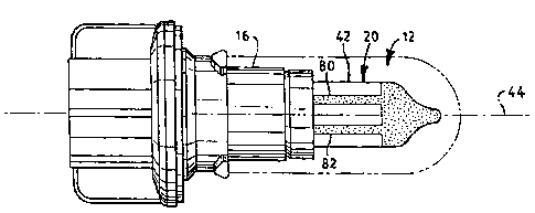
An example of a vehicle headlamp in accordance with the invention is shown in
FIGS. 1 and 2. Like elements in FIGS. 1 and 2 have the same reference
numerals. A
vehicle headlamp 10 includes a lamp capsule 12 mounted within a reflector 14.
A lamp
base 16 mechanically mounts lamp capsule 12 in reflector 14 and supplies
electrical energy
to lamp capsule 12. The open side of reflector 14 is closed by a light-
transmissive cover or
lens (not shown).
Lamp capsule 12 includes a lamp envelope 20 of a light-transmissive material,
such
as glass, which defines an enclosed volume 22. A low beam filament 24 and a
high beam
filament 26 are mounted within lamp envelope 20. Conductive support leads 30,
32 and 34
provide mechanical support for filaments 24 and 26 and supply electrical
energy to filaments
24 and 26. A lead frame 36 provides mechanical support for support leads 30,
32 and 34 and
filaments 24 and 26. Leads 30, 32 and 34 pass through a press seal 40 of lamp
envelope 20
and contact conductors in lamp base 16.
Lamp envelope 20 includes a generally tubular portion 42 having a central axis
44.
The tubular portion 42 is closed at one end by a tip-off portion, or dome, 50
and is closed at
the other end by press seal 40. In a preferred embodiment, dome 50 is shaped
to trap light
emitted by filaments 24 and 26 in the direction of dome 50 and to thereby
reduce glare. A
light-attenuating layer 52, such as black paint, covers the outside surface of
dome 50 and
prevents transmission of light through dome 50.
The reflector 14 has a reflecting surface 60 that may have one or more
sections,
each, for example, being a parabolic surface of revolution about an optical
axis of the
reflector. The lamp capsule 12 is positioned by base 16 such that filaments 24
and 26 are
located at or near the focal points of the reflecting surface, and the central
axis 44 of lamp
CA 02563486 2006-10-31
-(-
envelope 20 is co-linear with the optical axis of reflector 14. Light emitted,
for example, by
filament 24 is reflected by reflecting surface 60 in a forward direction
through an open side
of reflector 14, as indicated by rays 62. Light emitted by filament 24 and
reflected by
reflecting surface 60 is directed nearly parallel to the optical axis of
reflector 14 and
produces a desired beam pattern. Similarly, light emitted by filament 26 is
reflected by
reflecting surface 60 in a forward direction and produces a desired beam
pattern. Reflecting
surface 60 may have different parabolic sections and may be complex. The
reflecting
surface may include more than one parabolic reflector. The lamp capsule of the
present
invention may be used with a variety of different reflector configurations.
Because filaments 24 and 26 are spaced apart within lamp envelope 20 and have
different positions relative to the focal point of reflecting surface 60, they
produce different
beam patterns. Typically filament 24, which is located on or near the central
axis of lamp
capsule 12, is the low beam filament, and filament 26, which is spaced from
filament 24 and
is displaced axially toward press seal 40 relative to filament 24, is the high
beam filament.
As indicated above, a partially illuminated image of the high beam filament
may be
produced in the beam pattern of the vehicle headlamp when the low beam
filament is
energized. The image, which is caused by light emitted by the low beam
filament and
reflected by the deenergized high beam filament, contributes to glare.
According to a feature of the invention, the lamp capsule 12 includes at least
one
light-attenuating axial stripe on the lamp envelope. An embodiment of the lamp
capsule
including axial stripes is illustrated in FIGS. 3-5. Like elements in FIGS. 1-
5 have the same
reference numerals. In the example of FIGS. 3-5, light-attenuating axial
stripes 80 and 82
are provided on the outer surface of lamp envelope 20. Axial stripes 80 and 82
are spaced
apart from each other and are substantially parallel to central axis 44 of
lamp envelope 20.
Axial stripes 80 and 82 preferably extend over the entire length of the
tubular portion of
lamp envelope 20. The axial stripes may be any material which is substantially
opaque to
the light emitted by low beam filament 24 and which is compatible with the
environment of
the vehicle headlamp. In a preferred embodiment, the axial stripes may be
black paint.
The axial stripes 80 and 82 are positioned and dimensioned on lamp capsule 20
so
as to reduce or eliminate the ghost image of the high beam filament when the
low beam
filament is illuminated, while minimizing the adverse impact on total
illumination. More
CA 02563486 2006-10-31
particularly, stripes 80 and 82 are positioned and dimensioned to block light,
emitted by low
beam filament 24 and reflected by high beam filament 26, which would be
projected above
the horizontal plane in the low beam pattern.
Suitable geometries of the light-attenuating axial stripes are described with
reference to FIG. 5. As indicated above, at least one light-attenuating axial
stripe is
positioned on lamp envelope 20 to block light emitted by low beam filament 24
and
reflected by high beam filament 26. In the example of FIG. 5, axial stripes 80
and 82 are
equally spaced from a plane 90 containing filaments 24 and 26. Axial stripes
80 and 82 may
be defined by angular widths relative to central axis 44 and angular spacings
from plane 90.
Preferably, each axial stripe is spaced from plane 90 by an angle 94 relative
to central axis
44 in a range of about 17 to 20 degrees and has an angular width 92 relative
to central axis
44 in a range of about 1 to 16 degrees. In one example, angle 94 is about 18
degrees and
angle 92 is about 16 degrees. It may be observed that axial stripes 80 and 82
are
approximately spaced by the projected diameter of high beam filament 26 on
envelope 20.
This may be understood from the fact that a region of lamp envelope 20 between
axial
stripes 80 and 82 is shadowed by filament 26 when filament 24 is illuminated.
The widths
of axial stripes 80 and 82 are selected to block light emitted by filament 24
and having
grazing incidence on filament 26. It will be understood that it is not
practical to block all
light emitted by filament 24 and reflected by filament 26. In a preferred
embodiment, axial
stripes 80 and 82 have widths that are approximately equal to the diameter of
filament 26.
The axial stripes preferably extend the entire length of the tubular portion
of the lamp
envelope, but may have a shorter length within the scope of the invention.
In one example of a lamp capsule in accordance with the invention, lamp
envelope
20 has an outside diameter of 0.580 inches and filaments 24 and 26 are spaced
by 2.3
millimeters. Angle 92, representative of the width of axial stripes 80 and 82
is 16 degrees,
and angle 94, representative of one half the spacing between axial stripes 80
and 82, is 18
degrees.
Tests of lamp capsules with and without light-attenuating axial stripes as
described
above have demonstrated that European standards for vehicle beam patterns can
be achieved
more easily when the axial stripes are used.
CA 02563486 2006-10-31
_g_
It will be understood that the width, position, number of stripes and length
of stripes
may be varied within the scope of the invention. The number of axial stripes,
the length and
width of each axial stripe and the position of each axial stripe on lamp
envelope 20 are
functions of the diameter of lamp envelope 20, the sizes of filaments 24 and
26, the spacing
between filaments 24 and 26 and the acceptable reduction in total illumination
produced by
the axial stripes. The primary requirement is that one or more axial light-
attenuating stripes
be positioned to intercept at least a portion of the light emitted by the low
beam filament and
reflected from the high beam filament, with the high beam filament
deenergized.
A further feature of the invention is described with reference to FIG. 3.
Light-
attenuating rings 100 and 102 are applied to the outer surface of lamp
envelope 20. Light-
attenuating ring 100 is located at the lower end of tubular portion 42 of lamp
envelope 20
adjacent to base 16, and light-attenuating ring 102 is located at the upper
end of tubular
portion 42 adjacent to dome 50. Rings 100 and 102 control the length of a
clear zone of
lamp envelope 20 through which the light from filaments 24 and 26 can pass.
The filaments
24 and 26 are located relative to a base reference plane 104 in the
fabrication process. One
or both of rings 100 and 102 may be utilized. The rings 100 and 102 may be
added relative
to the base as a completion step in the calibration of the light source. A
metal cap 110 that
surrounds the bottom portion of the lamp capsule acts as a primary baffle,
with one or two
rings added if necessary as an optional trim or final calibration. The light-
attenuating layer
on dome 50 may be calibrated by the addition of ring 102. The rings 100 and
102 may or
may not be required, depending on the positioning of the edges of cap 110 and
the coating
on dome 50.
The masking of the filament ends with rings 100 and 102 generates filament
images
that have a sudden extinction of light. This permits fabrication of intensity
patterns with a
higher degree of control by portions of the reflector that have little, if
any, control without
these boundaries on the light transmitting area. The images from the region of
the reflector
close to the optical axis have a high degree of magnification that distorts
and enlarges the
filament image. Trimming one end of the distorted image permits control of a
portion of the
beam to the left of the vertical axis that can be used for horizontal aim. In
addition, the
trimmed images can be used to position the hot spot nearer to the horizon
while limiting
stray light above the horizon.
CA 02563486 2006-10-31
-9-
An additional feature of the invention is described with reference to FIGS. 6-
9.
Like elements in FIGS. 1-9 have the same reference numerals. A lamp capsule
190 is
shown in FIGS. 6-8. Low beam filament 24 is displaced from central axis 44,
typically by
about 0.030 inch, to limit wall reflections. The high beam filament 26 is
located in a plane
defined by central axis 44 and low beam filament 24 and is displaced radially
from low
beam filament 24, typically by about 0.090 inch. More specifically, each of
filaments 24
and 26 typically has a helical configuration. Filament 24 has a central axis
194, and
filament 26 has a central axis 196. The respective central axes 194 and 196 of
filaments 24
and 26 and central axis 44 of lamp envelope 20 are in a plane 192 (FIG. 8) and
are parallel
to each other. High beam filament 26 may be displaced axially toward press
seal 40,
typically by about one third of its length, with respect to low beam filament
24.
A support structure for filaments 24 and 26 includes support leads 200, 202
and 204,
and lead frame 36. In a preferred embodiment, the portions of support leads
200, 202 and
204 within lamp envelope 20 are substantially coplanar with filaments 24 and
26. The plane
192 containing filaments 24 and 26, and support leads 200, 202 and 204 is
preferably
parallel to the long dimension of press seal 40, as best shown in FIG. 8. This
configuration
permits the lamp capsule to be rotated about low beam filament 24 for left
hand drive and
right hand drive applications, as described below. Furthermore, the disclosed
filament and
filament support structure facilitates manufacturing of the lamp capsule. The
support
structure for filaments 24 and 26 is configured for an improved beam pattern
and reduced
glare in comparison with prior art vehicle lamp capsules.
Each filament lead is preferably provided with a sleeve 206 of molybdenum. The
sleeve 206 is attached to the filament lead by crimping and is welded to the
respective
support lead. Thus, where a filament lead is described as connected to a
support lead, it will
be understood that a sleeve is utilized.
Support lead 202 includes a lower segment 210 that is parallel to and spaced
from
central axis 44. An upper segment 212 of support lead 202 is bent in the plane
of filaments
24 and 26 toward press seal 40, and is connected to the lower ends of
filaments 24 and 26.
Support lead 200 includes a lower segment 220 that is parallel to and spaced
from central
CA 02563486 2006-10-31
-10-
axis 44, and an upper segment 222 that is angled toward central axis 44 in the
plane of
filaments 24 and 26. The upper segment 222 of support lead 200 is connected to
filament
lead 224 near the upper end of low beam filament 24. Preferably, filament lead
224 is nearly
perpendicular to central axis 44. The angle of upper segment 222 of support
lead 200,
typically about I 5° to 20°. is selected so that light emitted
by low beam filament 24 is
reflected downwardly by upper segment 222 when the lamp capsule is mounted in
a vehicle
lamp reflector. Because support lead 200 is located in the plane of filaments
24 and 26,
support lead 200 is at least partially shadowed by filament 24 when high beam
filament 26 is
illuminated.
Support lead 204 includes a lower segment 230 that is parallel to and spaced
from
central axis 44, and an upper segment 232 that is bent away from central axis
44 in the plane
of filaments 24 and 26. Upper portion 232 of support lead 204 is connected to
filament lead
234 from the upper end of high beam filament 26. In the embodiment of FIGS. 6-
8,
filament lead 234 is bent toward press seal 40, and includes a section that is
substantially
parallel to central axis 44. The connection between filament lead 234 and the
upper portion
232 of support lead 204 is made below filament 26 in a region between filament
26 and
press seal 40. Filament lead 234 is preferably in the plane of filaments 24
and 26, and is at
least partially shadowed by filament 26 when low beam filament 24 is
illuminated. In
addition, it may be observed that the support leads 202 and 204 for filament
26 are located
in the region between filament 24 and press seal 40 and have minimal impact on
light
emitted by filaments 24 and 26. In general, support leads 200, 202 and 204 are
configured
to limit blockage of light emitted by filaments 24 and 26 and to limit stray
reflections which
would produce glare.
An alternate embodiment of the filament support structure is shown in FIG. 9.
Like
elements in FIGS. 6-9 have the same reference numerals. The embodiment of FIG.
9 differs
from the embodiment of FIGS. 6-8 primarily with respect to the support lead
for the upper
end of high beam filament 26. A support lead 250 includes a lower segment 252
parallel to
and spaced from central axis 44, and an upper segment 254 parallel to central
axis 44, but
displaced outwardly in the plane of filaments 24 and 26 with respect to lower
segment 252.
CA 02563486 2006-10-31
Segments 252 and 254 are connected by an intermediate segment 256 disposed
between
filament 26 and press seal 40. An upper end of segment 254 may be bent
inwardly and
connected to a filament lead 260 of filament 26. Filament lead 260 may extend
upwardly at
an angle with respect to central axis 44. The segments of support lead 250 are
in the plane
of filaments 24 and 26. Upper segment 254 is shadowed by filament 26 when low
beam
filament 24 is illuminated, thus limiting light blockage and stray
reflections.
Schematic diagrams illustrating various orientations of the lamp capsule of
the
present invention are shown in FIGS. l0A-IOC. Like elements in FIGS. 1-lOC
have the
same reference numerals. FIGS. l0A-lOC represent the lamp capsule as viewed
along the
central axis 44 of lamp envelope 20. In FIG. 1 OA, plane 192, which contains
filaments 24
and 26 and is parallel to the plane of press seal 40, is oriented vertically.
Axial stripes 80
and 82 are spaced from plane 90, as described above. In FIG. 10B, the lamp
capsule is
rotated by approximately 45 degrees in a clockwise direction about filament 24
with respect
to the orientation of FIG. I OA. The orientation of FIG. lOB is used in a left
hand driving
vehicle headlamp. Axial stripe 80 reduces glare and provides a sharper
transition at the
upper boundary of the low beam pattern, as described above. In FIG. l OC, the
lamp capsule
is rotated approximately 45 degrees in a counterclockwise direction about
filament 24 with
respect to the orientation of FIG. 10A. The orientation of FIG. l OC is
utilized in a right
hand driving vehicle headlamp. Axial stripe 82 reduces glare and provides a
sharper
transition at the upper boundary of the low beam pattern, as described above.
It will be understood that the features of the lamp capsule described herein,
including the use of one or more axial stripes on the lamp envelope, the use
of one or more
light-attenuating rings on the lamp envelope, and the filament support
structure shown in
FIGS. 6-9 and described above, may be used separately or in any combination to
provide
lamp capsules with improved beam patterns and ease of manufacture.
While there have been shown and described what are at present considered the
preferred embodiments of the present invention, it will be obvious to those
skilled in the art
that various changes and modifications may be made therein without departing
from the
scope of the invention as defined by the appended claims.