Note : Les descriptions sont présentées dans la langue officielle dans laquelle elles ont été soumises.
CA 02564132 2009-05-14
1
GASTROSTOMY TUBE EXTENSION DEVICE
Field
[0001]
The present invention relates to a gastrostomy tube
extension device used for inserting or taking out a
gastrostomy tube into/from a patient's body for feeding
fluid substances such as liquid food into a stomach of a
patient.
Background
[0002]
Hitherto, feeding of fluid substances such as liquid
food or nutrient preparation using a gastrostomy tube has
been carried out for persons whose capability to take
food orally by their own abilities is deteriorated due to
aging or diseases (hereinafter referred to as a
"patient"). The gastrostomy tube typically includes a
tube member to be installed at a hole (fistula hole) for
dietary intake provided in a patient's body, an inner
fixing member, often a catheter balloon, fixed to a
distal portion of the tube member and installed inside of
a stomach wall and an outer fixing member mounted to a
proximal portion of the tube member and installed on the
side of the body skin. When inserting or taking out the
gastrostomy tube into/from the hole formed on the
patient's body, operation for insertion and taking-out
thereof is performed by a gastrostomy tube extension
device, as disclosed in JP-T-2000-507134.
[0003]
The gastrostomy tube extension device may include a
pushing rod which can be inserted into and taken out from
a fluid substance feed hole formed on the gastrostomy
tube, and an engaging member including an outer fixing
CA 02564132 2009-05-14
2
member engaging portion which can engage the outer fixing
member of the gastrostomy tube and a finger hook on which
a finger can be hooked. The inner fixing member can be
formed at the center of the distal end thereof with a
pushing rod engaging portion with which the distal
portion of the pushing rod can engage, so that the inner
fixing member is elongated when the pushing rod is
inserted into the fluid substance feed hole and the
pushing rod engaging portion is pushed toward the distal
end.
[0004]
Therefore, when the pushing rod is pushed into the
fluid substance feed hole while pulling the finger hook
of the engaging member toward the outside (toward the
proximal side of the gastrostomy tube) with fingers while
the outer fixing member engaging portion of the engaging
member is engaged with the outer fixing member, the inner
fixing member can be elongated and narrowed. Then, since
the inner fixing member in this narrowed state can pass
through the hole formed on a patient's abdominal part,
the gastrostomy tube can be placed in or taken out from
the hole. Also, when the inner fixing member is inserted
into the interior of the stomach wall and the force from
the pushing rod is released by pulling out the pushing
rod, the inner fixing member is brought into a swelled
state by its resiliency, and hence the gastrostomy tube
does not come out from the patient's body.
[0005]
when inserting or taking out the aforementioned
gastrostomy tube into/from a hole formed on the patient's
body, it may be necessary to manually maintain the
position of the engaging member with respect to the
pushing rod constant so that the thickness of the inner
fixing member
CA 02564132 2009-05-14
3
can be kept constant. In other words, with the
aforementioned gastrostomy tube extension device, the
operation to insert or remove the gastrostomy tube
requires great skill by the user, who has to maintain the
position by hand. In recent years, it has become more
common for "patients" to play a greater role in their
personal lives; it is now common for those requiring
gastrostomy tubes for themselves or their small children
to choose to maintain, and even replace, these tubes
without the help of a medical doctor or nurse. This
greater role of the patients, however, does require that
the insertion/removal of the gastrostomy tubes be
relatively uncomplicated to complete.
Summary of the Invention
[0006]
It is therefore desirable to provide a gastrostomy
tube extension device which can easily be inserted or
taken out. This can be achieved by fixing the degree of
extension of the gastrostomy tube during the procedure.
[0007]
A structural characteristic of the gastrostomy tube
extension device disclosed herein is the gastrostomy tube
extension device used for inserting or taking out the
gastrostomy tube into/from a hole on a patient formed
between a skin surface and the inner surface of a stomach
wall. A gastrostomy tube can include: an outer fixing
member to be installed at the hole on the skin surface
side; an inner fixing member to be installed on the inner
side of the stomach wall, a tube member for connecting
the outer fixing member and a proximal portion of the
inner fixing member, and a fluid substance feed hole
extending from the outer fixing portion to the inner
fixing portion.
CA 02564132 2009-05-14
4
A pushing rod that may be formed of a rod member
which can be inserted into the fluid substance feed hole,
can be capable of pushing the center portion of the
distal end of the inner fixing member toward the distal
end with the distal end portion of the rod, and may be
formed with a positioning engaging portion on the
peripheral surface of the proximal portion.
An engaging member capable of engaging the outer
fixing member and the pushing rod, can be used to
elongate the inner fixing portion when the pushing rod is
inserted into the fluid substance feed hole and the outer
fixing member, when the pushing rod is in a locked
position with respect to the engaging member and the
outer fixing member.
[0008]
In the gastrostomy tube extension device configured
as described above, the pushing rod can be provided with
a positioning engaging portion on the peripheral surface
of its proximal portion, which can be capable of engaging
the engaging member. Therefore, when the pushing rod is
inserted into the fluid feed hole of the gastrostomy tube
and the outer fixing member of the gastrostomy tube and
locked with the engaging member (achieved by pulling the
engaging member in the proximal direction of the pushing
rod), the inner fixing member is maintained in the
narrowed, extended state, due to the pressure the distal
end of the pushing rod exerts on the distal end of the
inner fixing member. Therefore, the operator who performs
the insertion or removal operation of the gastrostomy
tube can concentrate on the insertion or removal
operation, possibly using only one hand, without paying
attention to the degree of extension of the gastrostomy
tube. Consequently, insertion and removal of the
gastrostomy tube into/from the hole on the patient are
CA 02564132 2009-05-14
facilitated.
[0009]
Another structural characteristic of the gastrostomy
tube extension device is that the inner fixing member to
be installed on the inner side of the stomach wall can be
formed of a resilient material which is elongated when
the center of the distal end is pushed toward the distal
direction. The distal end of the pushing rod is capable
of pushing the center portion of the distal end of the
inner fixing member toward the distal end, and is formed
with a positioning engaging portion on the peripheral
surface of the proximal portion.
The engaging member may include a joint member being
connected to the gastrostomy tube and an engaging portion
being capable of engaging the positioning engaging
portion of the pushing rod, and elongating and narrowing
the inner fixing member when the pushing rod is inserted
into the fluid substance feed hole and the positioning
engaging portion and the engaging portion are engaged
respectively.
[0010]
In this case, since the engaging member is connected
to the gastrostomy tube via the joint member, the
operation to connect the engaging member with the
gastrostomy tube is no longer necessary, and the
operation of the device is made easier.
[0011]
Another structural characteristic of the gastrostomy
tube extension device is in that one or a plurality of
the positioning engaging
portions can be provided along the axial direction of the
pushing rod. With a plurality of positioning engaging
portions, the extended state of the gastrostomy tube can
be changed arbitrarily by selecting the positioning
CA 02564132 2009-05-14
6
engaging portion of the pushing rod to engage the second
engaging portion of the engaging member as needed.
Accordingly, versatility is provided, and hence one type
of gastrostomy tube extension device is suitable for
various body types.
Furthermore, adaptation of expansion properties or
other physical properties of the gastrostomy tube can be
made. For example, when inserting the gastrostomy tube
into the hole on the patient, the operation is performed
with the second engaging portion engaged with the
positioning engaging portion which provides the smallest
extension. Then, when taking out the gastrostomy tube
from the hole on the patient after having placed the
gastrostomy tube in the patient's body, the second
engaging portion can be engaged with another positioning
engaging portion.
Accordingly, the operation of the gastrostomy tube
can be performed with the tube in the extension state
optimal for each operation.
It is further noted that the insertion/removal
procedure with the present invention may be carried out
using only one hand, greatly increasing the freedom of
patients maintaining their gastrostomy tubes themselves.
According to one aspect of the invention there is
provided a gastrostomy tube extension device used for
inserting or taking out a gastrostomy tube into/from a
hole on a patient formed between the skin surface and the
inner surface of a stomach wall the gastrostomy tube
comprising: an outer fixing member to be installed at the
hole of the patient on the skin surface side, an inner
fixing member to be installed on the inner side of the
stomach wall which is formed of resilient material which
is elongated and narrowed when the center of the distal
end thereof is pushed toward the distal end; and a tube
CA 02564132 2010-09-13
6a
member for connecting the outer fixing member and the
proximal portion of the inner fixing member, and a fluid
substance feed hole extending from the outer fixing
portion to the inner fixing portion, the extension device
comprising: a pushing rod comprising a rod member which
can be inserted into the fluid substance feed hole, is
capable of pushing the center portion of the distal end
of the inner fixing member toward the distal end with the
distal end portion thereof, and is formed with a
positioning engaging portion on the peripheral surface of
the proximal portion and an engaging member including: a
joint member being connected to the gastrostomy tube, a
first engaging portion which is capable of engaging the
outer fixing member, and a second engaging portion which
is capable of engaging the positioning engaging portion
of the pushing rod, the engaging member elongating and
narrowing the inner fixing portion when the pushing rod
is inserted into the fluid substance feed hole and the
outer fixing member and the first engaging portion, and
the positioning engaging portion and the second engaging
portion are respectively engaged with each other, whereby
the gastrostomy tube extension device is properly
positioned, wherein the positioning engaging portion
comprises at least one engaging step portion that is
ring-shaped, and wherein the at least one engaging step
portions are formed at regular intervals.
According to another aspect of the invention there
is provided a gastrostomy tube extension device used for
inserting or taking out a gastrostomy tube into/from a
hole on a patient formed between a skin surface and an
inner surface of a stomach wall of the patient, the
gastrostomy tube comprising: an outer fixing member to be
installed at the hole on the skin surface side an inner
fixing member to be installed on the inner side of the
CA 02564132 2010-09-13
6b
stomach wall and which is formed of resilient material
which is elongated and narrowed when the center of the
distal end thereof is pushed toward the distal end; and a
tube member for connecting the outer fixing member and
the proximal portion of the inner fixing member; and a
fluid substance feed hole extending from the outer fixing
portion to the inner fixing portion, comprising: a
pushing rod formed of a rod member which can be inserted
into the fluid substance feed hole, is capable of pushing
the center portion of the distal end of the inner fixing
member toward the distal end with the distal end portion
of the rod, and is formed with a positioning engaging
portion on the peripheral surface of the proximal portion
of the rod and an engaging member including: a joint
member being connected to the gastrostomy tube and an
engaging portion being capable of engaging the
positioning engaging portion of the pushing rod, the
engaging member elongating the inner fixing member when
the pushing rod is inserted into the fluid substance feed
hole and the positioning engaging portion and the
engaging portion are engaged respectively with the
engaging member, whereby the gastrostomy tube extension
device is properly positioned, wherein the positioning
engaging portion comprises at least one engaging step
portion that is ring-shaped, and wherein the at least one
engaging step portions are formed at regular intervals.
Detailed Description
[00121
Hereinafter, referring to the drawings, an
embodiment of the present invention will be described.
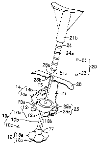
Fig. 1 shows a state in which a gastrostomy tube
extension device 20 according to the present invention is
mounted to a gastrostomy tube 10. The gastrostomy tube 10
includes an
CA 02564132 2006-10-16
WO 2005/105017 PCT/EP2005/004464
7
outer fixing member 10a, a tube member 10b connected to the
center of a lower end surface of-the outer fixing member
10a, and an inner fixing member 10c connected to the lower
end of the tube member 10b which are formed of polyurethane
as shown in Fig. 2. In the following description, the side
of the outer fixing member 10a is referred to as the upper
side, and the side of the inner fixing member 10c is
referred to as the lower side.
[0013]
The outer fixing member 10a includes a main body 12
including a thick ring-shaped body provided with a
vertically penetrating hole 11 at the center thereof; a
cylindrical joint member 12a projecting downward from the
center of a lower surface of the main body 12, outer
holding strips 13a, 13b projecting respectively from both
sides of the lower end portion on the outer peripheral
surface of the main body 12, and a lid member 14 connected
to a distal portion of one of the outer holding strip 13a.
Formed on the upper end portion on an inner peripheral
portion of the hole 11 formed on the main body 12 is an
engaging groove lla extending along the circumference
thereof. Each of the outer holding strips 13a, 13b is
formed into a thin plate of a substantially square shape in
plan view extending horizontally from the outer peripheral
surface of the main body 12 (the boundary between the outer
holding strip 13a and the lid member 14 is a straight
line).
[0014]
The lid member 14 includes a band-shaped joint member
14a joined to the distal portion of the outer holding strip
13a and a plug member 15 provided at the distal end of the
band-shaped joint member 14a. The band-shaped joint member
CA 02564132 2006-10-16
WO 2005/105017 PCT/EP2005/004464
8
14a has flexibility and can bend so as to rotate in the
vertical direction about the joint portion with respect to
the outer holding strip 13a, able to bend at a steep angle.
The distal portion of the band-shaped joint member 14a is
formed with a wide portion 14b having wider width than the
proximal side (at outer holding strip 13a), and the plug
member 15 is provided on the wide portion 14b. The plug
member 15 is provided on the wide portion 14b so as to face
the hole 11 when the band-shaped joint member 14a is bent
and the wide portion 14b is positioned on an upper surface
of the main body 12.
[0015]
The plug portion 15 is formed into a cylindrical
shape which can be inserted into the hole 11 and is short
in axial direction, and a projection 15a which can
detachably engage the groove lla of the hole 11 is provided
along the circumference thereof. Therefore, the groove lla
and the projection 15a can be engaged with each other by
bending the band-shaped joint member 14a and pressing the
plug member 15 against the hole 11, and consequently, the
hole 11 of the main body 12 can be clogged. Also, by
pulling the wide portion 14b of the band-shaped joint
member 14a forcedly upward from this state and releasing
the engagement between the plug member 15 and the hole 11,
the hole 11 of the main body 12 can be opened. The outer
fixing member 10a configured as described above has a
function to prevent the gastrostomy tube 10 from pulling
into the stomach by being fixed to the patient's skin
surface.
[0016]
The upper end of the tube member 10b is fixed to the
outer fixing member 10a while being inserted into the joint
CA 02564132 2006-10-16
WO 2005/105017 PCT/EP2005/004464
9
member 12a, and the interior of the tube member 10a defines
a feed path 16 for feeding fluid substance such as liquid
food. The upper end of the feed path 16 communicates with
the hole 11 of the outer fixing member 10a, and the feed
path 16 constitutes a fluid substance feed hole according
to the present invention in cooperation with the hole 11 of
the outer fixing member 10a. The tube member lOb is
provided with elasticity, and hence is narrowed by being
pulled, and returns to its original state when released
from the pulled force. The tube member l0b has a function
to prevent liquid or the like from leaking from the stomach
by being positioned at a hole 33 (see Fig. 7) formed on the
abdomen of the patient when-it is placed in the hole 33.
[0017]
The inner fixing member 10c includes a cylindrical
joint member 17 connected to the lower end of the tube
member lOb and an inner holding piece 18 connected to the
lower end opening edge of the joint member 17. The joint
member 17 is formed into a cylindrical shape which can
cover the lower end portion of the outer peripheral surface
of the tube member l0b, and is fixed to the tube member lOb
in a state in which the lower end of the tube member l0b is
inserted therein. The upper portion of the inner holding
piece 18 is connected to the lower peripheral edge of the
joint member 17 and includes a substantially dome-shaped
contact portion 18a which comes into contact with the
stomach wall when the inner fixing member lOc is positioned
in the stomach. The lower portion of the inner holding
piece 18 includes a plurality of band-shaped joint members
18b, in this embodiment four, joined to the lower edge of
the contact portion 18c and a connecting portion 18c for
CA 02564132 2006-10-16
WO 2005/105017 PCT/EP2005/004464
connecting the distal portions of the respective joint
members 18b.
[0018]
Formed at the center portion of the upper surface of
the contact portion 18a is a hole which communicates with
the feed path 16 of the tube member 10b. The hole
constitutes the fluid substance feed hole together with the
hole 11 of the outer fixing member 10a and the feed path
16. The center portion of the upper surface of the contact
portion 18a with which the stomach wall comes into contact
is formed into a flat shape. The plurality of joint
members 18b are provided at regular intervals around the
circumference at the lower end of the contact portion 18a,
extend separately axially from the lower edge of the
contact portion 18a downward respectively, and then are
converged at a lower position of the center axis of the
tube member 10b to constitute the connecting portion 18c
and thus are fixed together.
[0019]
In other words, the connecting portion 18c connects
the respective joint members 18b with each other by joining
the lower end portions of the respective joint members 18b,
and is positioned at a lower location of the center axis of
the tube member 10b. Therefore, the inner holding piece 18
is formed into substantially a spherical shape as a whole
with the pairs of opposing joint members 18b, 18b, and the
outline of the contact portion 18a forming circles
respectively.
[0020]
The contact portion 18a and the respective joint
members 18b are formed of soft resilient material having
flexibility, and are maintained in a substantially
CA 02564132 2006-10-16
WO 2005/105017 PCT/EP2005/004464
11
spherical shape as a whole by the resiliency thereof as
shown in Fig. 2 in a normal state. However, when the
connecting portion 18c is pressed downward, it is expanded
to a straight narrow state. In comparison with the sub-
portions of the contact portion 18a above the respective
joint members 18b, the sub-portions other than the above-
described sub-portions are thinner.
[0021]
Therefore, the contact portion 18a is constructed of
the portion extending from the joint members 18b and the
thinned portions therebetween, and hence when the
connecting portion 18c,is pulled downward, it is folded to
a specific shape and is easily narrowed. The connecting
portion 18c`is formed at the center with a hole, and an
engaging portion 19 of a short cylindrical shape is fixed
to this hole. The engaging portion 19 is formed at the
center thereof with a hole 19a for positioning the distal
portion of a rod (see Fig. 3) 21 described later. The
inner fixing member 10c configured as described above has a
function to be fixed to the inner surface of the stomach
wall of the patient and prevents the gastrostomy tube 10
from leaving the patient's body.
[0022]
The gastrostomy tube extension device 20 includes a
rod 21 used as the pushing rod, and an engaging member 22
according to the present invention as shown in Fig. 3. The
rod 21 is provided with a main body 21a formed of a rod-
shaped member possibly formed of stainless steel, and a
holding portion 21b possibly formed of plastic. The main
body 21a is provided with a pushing portion 23, possibly
formed of plastic, attached at the distal end thereof. The
pushing portion 23 includes a secured portion 23a fixed to
CA 02564132 2006-10-16
WO 2005/105017 PCT/EP2005/004464
12
the main body 21a which covers the peripheral surface of
the lower end portion of the main body 21a and a push-
insertion piece 23b extending downward from the lower end
of the secured portion 23a.
[0023]
The outer diameter of the secured portion 23a is set
to be larger than the diameter of the hole 19a of the
engaging portion 19, and the diameter of the push-insertion
piece 23b is set to be smaller than the diameter of the
hole 19a. Therefore, when the rod 21 is inserted downward
from the hole 11 of the gastrostomy tube 10, the push-
insertion piece 23b is inserted into the hole 19a, and the
secured portion 23a is located in such a manner that its
lower surface contacts the upper surface of the engaging
portion 19. Accordingly, when the rod 21 is pressed
downward into the gastrostomy tube 10, the inner fixing
member 10c extends and narrows.
[0024]
A cylindrical portion 24 configured integrally with
the holding portion 21b is formed on the upper portion of
the main body 21a and below the holding portion 21b so as
to cover the entire circumference of the main body 21a, and
a plurality of engaging step portions 24a as the
positioning engaging portions of the present invention are
formed on the outer peripheral surface thereof. Each
engaging step portion 24a is a ring-shaped projection
possibly of substantially triangular shape in vertical
cross-section formed on the peripheral surface of the
cylindrical portion 24 all along the circumference thereof,
and possibly five of these engaging step portions 24a may
be formed at regular intervals along the axial direction of
the cylindrical portion 24. The upper surface of the
CA 02564132 2006-10-16
WO 2005/105017 PCT/EP2005/004464
13
holding portion 21b is ideally formed into a curved surface
depressed into an arcuate shape for allowing the operator's
hand or finger, in particular, the thumb to fit for
operation.
[0025]
The engaging member 22 is formed into a shape as
shown in Fig. 3 possibly by machining a stainless steel
plate, and includes a lower engaging portion 25 as the
first engaging portion of the present invention, and an
upper engaging portion 26 as the second engaging portion of
the present invention. The lower engaging portion 25 and
the upper engaging portion 26 are connected by a joint
strip 27 of a vertically elongated rectangular plate shape.
The lower engaging portion 25 includes a holding strip 25a
of substantially U-shape in plan view which is formed from
the lower end of the joint strip 27, extending horizontally
toward the near side of the drawing and orthogonally to the
joint strip 27, and a pair of claw portions 25b provided in
parallel with the holding strip 25a so as to extend from
the both sides of the lower end portion of the joint strip
27, orthogonally to the joint strip 27 and at a distance
from the holding strip 25a. The inside of the
substantially U-shape of the holding strip 25a is formed
into a recess which can accommodate the joint member 12a of
the outer fixing member 10a and the distance between the
holding strip 25a and the claw portion 25b is set to a
distance which can clamp the outer holding strips 13a, 13b.
[0026]
The upper engaging portion 26 is formed so as to
extend from the upper end of the joint strip 27
horizontally toward the near side of the drawing and
orthogonally to the joint strip 27, and is configured by a
CA 02564132 2006-10-16
WO 2005/105017 PCT/EP2005/004464
14
laterally elongated part extending from both sides of the
joint strip 27. The length of the upper engaging portion
26 in the fore-and-aft direction is set to be short,
relative to the length of the holding strip 25a, and is
formed with an engaging recess 26a in the front center
which can engage the respective engaging step portions 24a.
A pair of projections 26b for preventing the engagement
with the engaging step portion 24a from being released
project downward at both sides of the engaging recess 26a
of the front portion of the upper engaging portion 26. In
addition, laterally both side portions of the upper
engaging portion 26 may be curved downwardly so as to
facilitate operation performed with the operator's hand
hooked therewith, and the distal portion of the holding
strip 25a may be curved upward so as to prevent engagement
with the outer holding strips 13a, 13b from being released.
[0027]
In this structure, in order to place the gastrostomy
tube 10 in the hole 33 formed on the abdominal part of the
patient, the wide portion 14b is pulled to open the hole 11
of the outer fixing member l0a and the rod 21 is inserted
from the hole 11 toward the lower side of the tube member
10. Then, the push-insertion piece 23b of the rod 21 is
aligned with the engaging portion 19 of the inner fixing
member 10c and pushed into the hole 19a. Subsequently, the
engaging member 22 is assembled to the gastrostomy tube 10
and the rod 21 in a state in which the outer holding strips
13a, 13b of the gastrostomy tube 10 in this state are
clamped between the holding strip 25a and the claw portions
25b and the main body 21a is positioned in the engaging
recess 26a to obtain the state shown in Fig. 1 or Fig. 4
CA 02564132 2006-10-16
WO 2005/105017 PCT/EP2005/004464
(the direction of the gastrostomy tube 10 is different from
Fig. 1).
[0028]
Subsequently, in a state in which the operator holds
down the upper surface of the holding portion 21b by hand
to prevent the push-insertion piece 23b from coming apart
from the hole 19a, the operator hooks his fingers with the
lower surface of the upper engaging portion 26 and pulls
the engaging member 22 upward so that the edge of the
engaging recess 26a is engaged with the predetermined
engaging step portion 24a, for example, the engaging step
portion 24a located at the center. Accordingly, as shown
in Fig. 5, the inner fixing member 10c extends straight and
is narrowed, and hence the tube member 10b and the inner
fixing member 10c take a shape similar to one single rod.
[0029]
In this case, not only the inner fixing member 10c,
but also the tube member 10b is brought into an extended
state. The gastrostomy tube 10 and the gastrostomy tube
extension device 20 are assembled in a state in which the
outer holding strips 13a, 13b are prevented from separating
from the holding strip 25a by the curved portion at the
distal end of the holding strip 25a, and the engaging step
portion 24a of the rod 21 is prevented from separating from
the engaging recess 26a by the projection 26b as shown in
Fig. 6.
[0030]
Subsequently, the gastrostomy tube 10 is inserted
into the hole 33 formed on an abdominal wall 31 and a
.stomach wall 32 of the patient shown in Fig. 7 in the
extended state as shown in Fig. 5. When the inner fixing
member 10c enters the patient's stomach, the operator pulls
CA 02564132 2006-10-16
WO 2005/105017 PCT/EP2005/004464
16
the engaging member 22 upward while hooking his/her finger
on the lower surface of the upper engaging portion 26, and
separates the engaging recess 26a from the engaging step
portion 24a as well as separating the holding strip 25a and
the claw portion 25b from the outer holding strips 13a,
13b, whereby the engaging member 22 is removed from the
gastrostomy tube 10. Then, the operator pulls out the rod
21 from the gastrostomy tube 10, and then bends the band-
shaped joint member 14a to press the plug member 15 against
the hole 11 to clog the hole 11 of the main body 12.
[0031]
Accordingly, as shown in Fig. 7, the inner fixing
member 10c returns to the original substantially spherical
shape due to its resiliency, and the upper surface of the
contact portion 18a comes into contact with the inner
surface of the stomach wall 32. The tube member 10b is
also restored to the original state. Consequently, the
gastrostomy tube 10 is prevented from leaving the hole 33,
and maintains the state of being attached to the abdomen of
the patient. The portions of the abdominal wall 31 and the
stomach wall 32 near the hole 33 are fixed so as not to be
displaced in position from each other. In this case, it is
preferable to leave a slight gap between the surface of the
abdominal wall 31 and the lower surface of the outer fixing
member 10a, so that a slight degree of freedom is provided
between the gastrostomy tube 10 and the hole 33.
[0032]
Then, when feeding fluid substance such as liquid
food or nutrient preparation to the patient, the hole 11 of
the outer fixing member l0a is opened, and a fluid feed
tube (not shown) is connected to the hole 11. In this
state, the fluid substance is fed from an opening at the
CA 02564132 2006-10-16
WO 2005/105017 PCT/EP2005/004464
17
end of the fluid feed tube into the fluid feeding tube.
Consequently, the fluid substance is fed from the fluid
feed tube via the hole 11 and the feed path 16 into the
patient's stomach. In this case, the fluid substance coming
out from the lower end opening of the tube member 10b
passes from inside the inner fixing member 10c through the
respective joint members 18b into the stomach. After use,
the operator removes the fluid feed tube from the outer
fixing member 10a and closes the hole 11.
[0033]
When a physical property of the gastrostomy tube 10
is changed, such as expansion after after a certain period
of use, and hence replacement is needed, the rod 21 and the
engaging member 22 are mounted to the gastrostomy tube 10
in the abdomen of the patient as in the aforementioned
operation. In this case, when the gastrostomy tube 10 has
expanded, the engaging recess 26a of the engaging member 22
is engaged at the uppermost engaging step portion 24a or
the second engaging step portion 24a from the top.
Accordingly, the inner fixing member 10c can be brought
into a narrow width which is suitable for its removal. The
gastrostomy tube 10 is taken out from the patient's body
together with the rod 21 and the engaging member 22, with
the inner fixing member 10c narrowed as described above.
Then, the new gastrostomy tube 10 is attached to the
patient's body as in the aforementioned operation.
[0034]
As described above, the gastrostomy tube extension
device 20 according to this embodiment includes the rod 21
and the engaging member 22. Then, the rod 21 is provided
at the lower end thereof with the push-insertion piece 23b
which is engageable with the hole 19a of the engaging
CA 02564132 2006-10-16
WO 2005/105017 PCT/EP2005/004464
18
portion 19 provided on the gastrostomy tube 10, and on the
peripheral surface of the upper portion of the rod 21 with
the engaging step portions 24a. The engaging member 22 is
provided with the lower engaging portion 25 engageable with
the outer holding strips 13a, 13b of the gastrostomy tube
and the upper engaging portion 26 engageable with the
engaging strips 24a of the rod 21.
[0035]
Therefore, when the rod 21 is inserted into the
gastrostomy tube 10, and the outer holding strips 13a, 13b
are engaged with the lower engaging portion 25, by pulling
the engaging member 22 upward and causing the upper
engaging portion 26 to engage with the predetermined
engaging step portion 24a, the inner fixing member 10c is
maintained in a thinned state. Therefore, the operator can
concentrate on the insertion or removal operation without
paying attention to the degree of extension of the
gastrostomy tube 10. Consequently, insertion and removal
of the gastrostomy tube 10 into/from the hole 33 on the
patient are made easy.
[0036]
The distal portion of the holding strip 25a of the
lower engaging portion 25 is bent upward and hence it is
hard for the lower engaging portion 25 to separate from the
outer holding strips 13a, 13b, and a pair of the
projections 26b are formed at the ends of the opening of
the engaging recess 26a on the front portion of the upper
engaging portion 26, so that it is hard for the upper ,
engaging portion 26 to separate from the engaging strips
24a of the rod 21. Therefore, the gastrostomy tube
extension device 20 maintains stable extension of the
CA 02564132 2006-10-16
WO 2005/105017 PCT/EP2005/004464
19
gastrostomy tube 10, never separating from the gastrostomy
tube 10.
[0037]
Also, the engaging step portions 24a may be formed at,
regular intervals, and the length of the gastrostomy tube
can be extended by stages. Accordingly, versatility is
provided, and hence one type of gastrostomy tube extension
device 20 may be sufficient for insertion and removal of
the various gastrostomy tubes. Also, since the engaging
step portion 24a to be engaged with the engaging recess 26a
may be selected according to the change in the expansion or
other physical properties of the gastrostomy tube 10, the
operation in the optimal state is achieved.
[0038]
The gastrostomy tube extension device according to
the present invention is not limited to the aforementioned
embodiment, and may be changed as needed within the
technical scope of the present invention. For example,
although the gastrostomy tube 10 and the engaging member 22
in the aforementioned embodiment are separate members, they
may be formed integrally. In the aforementioned
embodiment, although five engaging step portions 24a are
formed on the rod 21, the number of the engaging step
portions 24a may be plural of four or smaller, or six or
larger, or may be single. The joint members 18c may also
vary in number or shape, even perhaps being formed into one
member, within the scope of this disclosure.
[0039]
In addition, it is also possible to form the engaging
step portion 24a to have an angular portion having a ridge
line 34b at the center like the engaging step portion 34a
formed into the cylindrical portion 34 shown in Fig. 8
CA 02564132 2006-10-16
WO 2005/105017 PCT/EP2005/004464
instead of a smoothly curved shape. This arrangement
further ensures engagement with respect to the engaging
recess 26a. Further, instead of a ring shape, the engaging
step portion may be formed of a projection projecting from
a predetermined position on the cylindrical portion or may
be formed of a recess with which the upper engaging portion
26 can engage. Also, the shapes or materials of other
portions constituting the gastrostomy tube 10 and the
gastrostomy tube extension device 20 may also be changed as
needed.
[Brief Description of the Drawings]
[0040]
[Fig. 1] Fig. 1 is a perspective view showing a
state in which a gastrostomy tube extension device
according to a first embodiment of the present invention is
mounted to a gastrostomy tube.
[Fig. 2] Fig. 2 is a perspective view of the
gastrostomy tube.
[Fig. 3] Fig. 3 is a perspective view of the
gastrostomy tube extension device.
[Fig. 4] Fig. 4 is a front view showing a state in
which the gastrostomy tube extension device is mounted to
the gastrostomy tube.
[Fig. 5] Fig. 5 is a front view showing a state in
which the gastrostomy tube is extended by the gastrostomy
tube extension device.
[Fig. 6] Fig. 6 is a cross-sectional view showing a
state in which an engaging step portion and an engaging
recess are engaged.
[Fig. 7] Fig. 7 is a cross-sectional view showing a
state in which the gastrostomy tube is placed in the
patient's body.
CA 02564132 2006-10-16
WO 2005/105017 PCT/EP2005/004464
21
[Fig. 8] Fig. 8 is a front view showing a
modification of the engaging step portion.