Note : Les descriptions sont présentées dans la langue officielle dans laquelle elles ont été soumises.
CA 02564172 2006-10-24
- 1 -
METHOD FOR THE APPLICATION OF A PROTECTIVE COATING TO A
THERMALLY STRESSED COMPONENT
TECHNICAL FIELD
The present invention relates to the field of thermal
machines and components which are subjected to high
thermal stress in use, and are provided with a heat
insulation layer or a metallic protective layer. It
refers, in particular, to a method for the repair of
damaged places on these layers.
PRIOR ART
Components subjected to high thermal stress, such as
are used, for example in the blading, the lining of the
combustion chamber or as protective shields in the hot-
gas duct of a gas turbine, are often covered with a
metallic protective layer or with a multilayer heat
insulation layer, in order to protect the basic
material lying underneath it against the high hot-gas
temperatures. The multilayer heat insulation layer in
this case comprises a bonding layer (bond coating BC)
applied to the basic material and the actual heat
insulation layer (thermal barrier coating TBC) which
mostly consists of a ceramic material. During
operation, a thermally grown oxide layer (thermally
grown oxide TGO) also forms at the boundary between the
bonding layer and the heat insulation layer and
protects the bonding layer against further oxidation
and corrosion and further improves the bonding of the
heat insulation layer for a specific lifetime range.
Owing to the constant alternating thermal load and
influence of the flowing hot gases and of foreign
bodies entrained in the hot-gas stream, it may happen
that, during operation over a lengthy period of time,
there are local peelings (and consumption, for example
CA 02564172 2006-10-24
2 -
due to erosion) of the protective coating which then
have to be rectified as quickly and as reliably as
possible, so that operation can be resumed as quickly
as possible and maintained, undisturbed, for as long as
possible. For rectification, the sequence of layers of
the protective coating has to be built up again in
succession in the regions of the local damage, so that
the component is fully protected again.
It is also conceivable, however, that, on a component
which is otherwise provided with a protective coating,
there are from the outset untreated places, for example
weld seams or the like, which are free of protective
coating and which subsequently have to be provided
locally with a protective coating in the form of a
metallic protective layer or of a ceramic heat
insulation layer.
A method for rectifying a metallic protective layer has
already been described in the publication US-A-
6,569,492. EP-Bl-O 808 913 discloses a method for
rectifying a ceramic heat insulation layer.
Further rectification methods are known from the
publications US-A-5,735,448, US-A-6,042,880, US-A-
6,203,847, US-A-6,235,352, US-A-6,274,193, US-A-
6,305,077, US-A-6,465,040, US-A-6,605,364, EP1304446A1
and US 5,972,424.
In the known rectification methods for protective
coatings, the following problems arise:
- It is in the nature of metallic protective layers or
PC/TBC multilayer systems that the edges of the
damaged or peeled-off places have a random
configuration without a specific form. There has
hitherto been no proposal for classifying the damage
as a precondition for a decision on repairability and
CA 02564172 2006-10-24
- 3 -
the use of a corresponding standardized preparation
of the damaged place.
- Regions which have been predamaged during operation
in the metallic protective layer or the BC/TBC
multilayer system, but do not appear visibly, cannot
be detected in the known methods and therefore also
cannot be repaired. This results in a high risk of
failure of the component, even if the coating has
been rectified locally. So that a full lifetime cycle
can be ensured, the entire coated surface or, in
particular, the regions put at risk, that is to say
regions subjected to particularly high thermal
mechanical load, must be examined for mechanical
integrity by means of a suitable nondestructive test
method.
- Since the edge regions of the damaged coating
surfaces are irregular, they may be very steep and
not have a sufficient slope between the basic
material, the BC layer and the TBC layer. If special
precautions are not taken, this may result in
uncontrolled preparation during cleaning (including
the risk of damaging the contiguous intact coating
surfaces), and an overlap effect may occur during the
subsequent recoating. This may lead to mismatches in
the BC/TBC multilayer system. Components repaired in
this way are exposed to a high risk of local peeling
on account of a local mismatching of the coefficients
of thermal expansion under thermal alternating load.
According to the known rectification methods, the
local repair of protective coatings is carried out
outside the thermal machine. This requires the
demounting and transport of the components to be
repaired and leads to losses of time and increased
costs.
CA 02564172 2010-11-22
e J
4 -
PRESENTATION OF THE INVENTION
The object of the invention is to specify a method for
the rectification of local damage or for filling up
local untreated places, which avoids the disadvantages
of known methods and is distinguished, in particular,
by a high quality and load-bearing capacity of the
processed regions. In particular, the method is to be
capable of being carried out on the spot on components
installed in the machine (on-site) and on components
demounted from the machine (off-site).
The essence of the invention is, during the
pretreatment of the places to be processed, to process
the edge regions of the layers ending at the local
damage or untreated place, in such a way that the
layers are stripped away in steps in the edge regions,
in that the circumference of the stripped-away surface
of the individual layers decreases in steps from the
outermost layer of the component as far as the surface
of the basic material and a mask of appropriate size is
used for defining the size of that surface of each
layer which is to be stripped away. The edge regions of
the individual layers are therefore processed in
succession, in that each layer is stripped away through
and by means of a mask assigned to it. Using masks
which are adapted with the size of their mask aperture
to each layer of the layer sequence, the geometry and
form of the critical edge layers can be set reliably
and accurately during processing.
Within the second step of the method according to the
invention, for the purpose of refilling the damaged
place, the new layers are applied by means of masks
according to the size of the stripped-away layer. The
use of masks of various sizes one after the other
avoids overlaps of the applied layers with the
CA 02564172 2006-10-24
- 5 -
contiguous layers present. By means of the masks, the
lateral extent of the applied layer regions can be
limited such that the applied layers do not at the edge
significantly overlap the layers already present and
therefore form edge regions of reduced strength and
stability which are conducive to later peeling off. The
masks used in the application of the layers have mask
apertures which increase successively in the same way
as in the case of the masks for processing.
Preferably, the individual layers are stripped away in
the edge regions of the local damage in such a way that
the ends of the individual layers are sloped uniformly.
A uniform slope of the layer ends is achieved, for
example, by means of a sandblasting method. The amount
of slope, that is to say the angle of the slope in
relation to the surface normal, depends in this case on
the sandblasting parameters and the material parameters
of the layers to be stripped away. The slope forms an
angle in relation to the surface normal in a range of
to 75 , preferably of 60 . The slope achieved is
uniform in so far as the angle of the slope is
essentially identical within a layer and over the
entire circumference of the damaged place, that is to
25 say is identical in so far as it can be achieved by
means of a sandblasting method or other blasting
method. The uniformly sloped edge regions thus go from
the bottom upward along the layer sequence, that is to
say from the surface of the basic material toward the
30 outermost layer of the layer sequence, increasingly
outward and back in steps, so that a series of
"terraces" with sloped walls between the terrace levels
is obtained.
Stepping the stripping away of the layers affords the
advantage that, when the corresponding new layers are
applied for the purpose of filling up the damaged
CA 02564172 2006-10-24
- 6 -
place, overlaps from layer to layer are avoided, and
new layer material is applied only to the layer
intended for it and does not pass on to the following
layer.
The sloped ends of the layers afford the additional
advantage of an improved bonding of the newly applied
layers.
Preferably, for safety reasons, a sufficiently broadly
selected region of the layers ending at the local
damage or untreated place is stripped away, so that
irregularities in the critical edge regions can be
reliably ruled out. That is to say, not only are the
obviously damaged places stripped away, but also
regions around the obvious damaged place, which
likewise have to be repaired on account of cracks or a
damaged bonding layer (BC) . The areal extent of the
damaged place which has to be repaired is thus defined.
Furthermore, the depth extent of the damaged place is
also defined, that is to say which part regions of the
composite layer formation have to be repaired, such as,
for example, only TBC or TBC/BC or TBC/BC/BM. The
amount of the region selected for repair and the
presence of hidden damaged regions are detected, for
example, by means of a nondestructive method, such as
FSECT (Frequency Scanning Eddy Current Technique).
Preferably, masks with a rounded, in particular
circular, mask aperture are used. The use of such a
mask form, in contrast to a form with corners, avoids
stresses which could emanate from pointed corners.
A particularly high quality of the rectified or filled-
up region is obtained when, within the second step,
before the application of a layer, the surface of the
layer lying underneath is processed, for example
roughened, in order to improve the bonding of the layer
CA 02564172 2006-10-24
- 7 -
to be applied. This takes place preferably by means of
sandblasting or blasting with ceramic blasting
material.
In order to obtain as smooth a surface of the coated
component as possible after and in spite of the repair,
it is advantageous if, after the application of the
layers, the surface is processed in the region of the
prior local damage or untreated place in order to
eliminate unevennesses, this preferably taking place by
means of grinding and/or polishing.
In order to obtain reliable evidence of the success of
a repair, it is advantageous if, after the elimination
of the local damage or untreated place, the region of
the prior local damage or untreated place is subjected
to a quality test. This takes place preferably by means
of nondestructive methods, in particular thermography
or FSECT (Frequency Scanning Eddy Current Technique).
The method according to the invention has proved
appropriate in a coating which constitutes a heat
insulation layer system which comprises a bonding layer
applied to the basic material and a heat insulation
layer applied to the bonding layer.
Advantageously, the method is carried out on the spot
on installed components, small portable processing
systems, in particular for cleaning and plasma
spraying, being used for processing the local damage or
untreated place. The method is likewise also suitable,
of course, for off-site repairs on demounted
components.
The method according to the invention is suitable both
for components which have been damaged during
operational use and for new components which have been
CA 02564172 2010-11-22
8 -
damaged, for example, during assembly or during
transport.
So that a component can be treated in full within the
scope of the method according to the invention, it is
advantageous if, in the first place, the surface of the
component is examined for mechanical integrity at least
in regions which are at particular risk such as, for
example, the pressure side and leading edge of turbine
blades, by means of a non-destructive test method, and
in this case the areas to be repaired are identified
and their extent is defined. For this purpose,
preferably, FSECT (Frequency Scanning Eddy Current
Technique) is used.
According to a further broad aspect of the present
invention there is provided a method for the
elimination of local damage or an untreated place in a
heat insulation layer or in a metallic protective layer
on a component for use under high thermal stress and
which consists of a basic material. In a first step the
local damage or an untreated place is pretreated and in
a second step, layers necessary for eliminating the
local damage or untreated place are applied. The method
is characterized in that in the first step the edge
portions of the individual layers of the heat
insulation layer are stripped away by means of
sandblasting or a blasting method with ceramic blasting
material one after the other in steps by means of masks
of different size. The size of the masks use becomes
successively larger or successively smaller from step
to step so that the extent of the stripped-away surface
of the individual layers of the heat insulation layer
CA 02564172 2011-06-23
- 8a -
decreases or increases, respectively, in steps from the
outermost layer of the heat insulation layer of the
component up to the surface of the basic material. The
individual layers are stripped away in the edge regions
of the local damage in such a way that the ends of the
individual layers are sloped uniformly. The angle of
the slope is essentially identical within a layer and
over the extent of the edge regions. In the second step
the layers necessary for eliminating the local damage
or untreated place are applied one after the other
through masks of different size with the size of the
masks being assigned to each individual layer.
BRIEF EXPLANATION OF THE FIGURES
The invention will be explained in more detail below by
means of exemplary embodiments, in conjunction with the
drawing in which:
fig. 1 shows a photographic illustration of a top view
of cleaned local damage, prepared by the method
according to the invention for recoating, of a
component or substrate provided with a heat
insulation layer;
fig. 2 shows the component from fig. 1 after the
recoating and subsequent treatment of the
surface;
fig. 3 shows a diagrammatic perspective illustration
of the use of a typical mask for the
pretreatment and recoating of local damage or
of an untreated place;
CA 02564172 2006-10-24
- 9 -
fig. 4 shows a micrograph through repaired local
damage with overlapping of the renewed bonding
layer, which overlapping occurs because of the
absence of masking and would be avoided by
means of the method according to the invention;
fig. 5 shows an enlarged illustration of the
micrograph from fig. 4;
fig. 6 shows a micrograph of an overlap of the renewed
bonding layer along a sloped edge of the heat
insulation layer, said micrograph being
obtained when work is carried out without masks
or with unsuitable masks;
fig. 7 shows, in various part figures, different steps
in the rectification on the spot or off-site of
local damage to an operationally stressed
component provided with a heat insulation
layer, in a preferred exemplary embodiment of
the method according to the invention; and
fig. 8 shows, in various part figures, different steps
in the local application on the spot or off-
site of a new heat insulation layer for the
purpose of refilling a damaged place or a local
untreated place.
WAYS OF IMPLEMENTING THE INVENTION
A first step for rectifying a damaged metallic or
BC/TBC coating on the basic material of a component
comprises a division of the defects into specific
categories, followed by the decision as to which
defective coating part region can be rectified and by
which standardized methods. For this purpose, the
entire coated surface of the component or at least the
CA 02564172 2006-10-24
- 10 -
areas which are at particular risk are investigated for
mechanical integrity by means of nondestructive test
methods. A nondestructive test method which comes under
particular consideration in this case is FSECT
(Frequency Scanning Eddy Current Technique), in which
the eddy currents induced in the component are
investigated and evaluated as a function of the
frequency.
When these preparatory investigations are concluded,
masks 21 of the type illustrated in fig. 3 are
selected, the mask apertures 22 of which correspond to
the extent of the defect. That is to say, the mask
apertures cover the size of the obvious damaged place
and further regions around this obvious damaged place
which have been assessed as damaged by virtue of a
nondestructive inspection (including a safety
addition) . The size of the mask aperture 22 is in this
case selected such that, for safety reasons, an edge
region of sufficient width is always stripped away in
the layer to be stripped away, so as to remove all
damaged areas reliably, but without impairing the
undamaged areas of the layer. The masks 21 are laid
onto the substrate or component 20, whereupon the
damaged coating is successively stripped away through
the mask aperture 22. Masks 21 with mask apertures 22
of different size, more precisely with a successively
smaller size, are used one after the other, in order to
remove the metallic protective layer or the TBC layer,
the BC layer and any oxidized basic material of the
substrate. With the use of the masks 21, a new step or
"terrace level" is produced in each layer. The steps
resulting from this are illustrated in figure 7b. The
method can also be carried out in that the masks used
one after the other become successively larger, that is
to say first the smallest mask and lastly the largest
mask are used. If, for example, sandblasting is used as
CA 02564172 2006-10-24
- 11 -
a stripping-away method, uniformly sloped edge regions
16 are produced in fig. 1, 7 and 8. These are critical
for the subsequent rectification or filling-up process,
in particular for the bonding of the newly applied
layers.
In the subsequent application of new TBC/BC layer
sequences or metallic protective layers, equivalent or
identical masks are used in order to limit the lateral
extent of the newly applied layers and thus to prevent
edge overlaps of the newly applied layers and of the
existing layers from occurring. Examples of overlaps of
this kind are shown in fig. 4, 5 and 6. Fig. 4 and 5
show, in a different magnification, micrographs of an
edge overlap 25 of a subsequently applied bonding layer
17, the result of this overlap being that the ceramic
heat insulation layer 13 lying above it experiences
mechanical weakening there. Fig. 6 shows an overlap 25
on an oblique edge region of the heat insulation layer
13, said overlap likewise leading to mechanical
weakening.
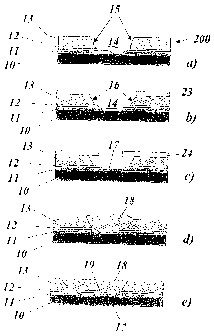
Fig. 7 reproduces, in various part figures, different
steps in the rectification of local damage to a
component 200 provided with a BC/TBC heat insulation
layer system, in a preferred exemplary embodiment of
the method according to the invention. According to
fig. 7a, to protect the component 200, the basic
material 10 of the component 200 has applied to it a
layer sequence consisting of a bonding layer 11, of a
thermally grown oxide layer 12 and of a ceramic heat
insulation layer 13 which has local damage 14. The
individual layers 11, 12 and 13 have irregularly formed
edge regions 15 in the region of the local damage 14.
When the local damage 14 is discovered and selected for
repair, according to fig. 7b, in a first step, the
CA 02564172 2006-10-24
- 12 -
irregular edge regions 15 of the layers are
successively stripped away through suitable masks 23,
so that all the layers 11, 12, 13 have uniformly sloped
edge regions 16 which border an opening in the layer
sequence with a diameter increasing outward. Only one
mask 23 is depicted in fig. 7b. In actual fact, the
individual layers 11, 12, 13 are stripped away one
after the other in part steps, using a mask coordinated
in each case with the layer, so that, in the case of
the three layers 11, 12, 13, at least three masks 23
are employed.
For stripping away the layer 13, a first mask is used,
having the size of the largest opening, that is to say
the opening 14 on the upper surface of the layer 13.
Stripping away is then carried out up to the surface of
the layer 12. The next mask possesses an aperture with
a slightly smaller size, that is to say that of the
opening 14 on the upper surface of the layer 12.
Stripping away is then carried out up to the surface of
the layer 12. The next mask, in turn, is smaller with
an aperture identical to the opening 14 on the surface
of the layer 11.
The staggered stripping away of the individual layers
to produce a terrace-shaped opening 14, as in figure
7b, may also be carried out, using the masks mentioned
in reverse order of size, by commencing with the
smallest mask and ending with the largest mask.
When the local damage 14 is pretreated in this way, the
removed layers can be replaced one after the other.
Fig. 7c shows the replacement of the bonding layer 11
by a renewed bonding layer 17 which takes place through
a mask 24 so as to avoid overlaps. In the same way, a
renewed heat insulation layer 18 is also applied (fig.
7d) which is then adapted (fig. 7e) to the remaining
surface by grinding and/or polishing. When the
component 200 thus repaired is exposed to high
CA 02564172 2006-10-24
- 13 -
temperatures, a newly grown oxide layer 19 (fig. 7e)
forms, so that the original layer sequence is restored
completely.
Whereas fig. 7 relates to the rectification of local
damage 14, fig. 8 reproduces, in various part figures,
different steps in the application of a new heat
insulation layer for refilling a local untreated place
14' of a component 300 provided with a BC/TBC heat
insulation layer system. Such a local untreated place
14' occurs, for example, in the region of a weld seam
when two parts already previously coated are welded to
one another. Since such a component 300 has to be
processed even before its first use, in order to
complete the heat insulation layer, there is not yet
here a thermally grown oxide layer present in the layer
sequence (fig. 8a) . In this case, too, first, the
irregular edge regions 15 of the layers 11, 13 are
changed to uniformly sloped edge regions 16 through
masks 23 by controlled stripping away (fig. 8b) . The
layers 17 and 18 are then newly applied (fig. 8c and d)
through corresponding masks 24 and adapted to the
surface (fig. 8e) . What is achieved by using plasma
spraying or a spraying method which transfers the
material to be applied into a fusible or molten phase
is that the new layers 17, 18 are applied the openings
14' according to the mask aperture.
A photographic illustration of local damage to a
component 100 before the application of the layers and
after repair is shown in fig. 1 and 2. Fig. 1 shows, in
a top view from above, the pretreated local damage 14
with the uncovered basic material 10, the bonding layer
11 and the heat insulation layer 13. The use of masks
of the type illustrated in fig. 3, with circular mask
apertures, results, in fig. 1, in edge regions with a
clearly visible uniform slope. Fig. 2 shows the
CA 02564172 2006-10-24
- 14 -
surface, adapted by grinding, of the renewed heat
insulation layer 18 after the repair (comparable to
fig. 7e and 8e).
The processing of the local damages 14 or untreated
places 14' takes place preferably on the installed
component "on the spot", blasting processes with
ceramic blasting material or sandblasting being used
for cleaning (and similar blasting processes) and for
stripping away, and, to apply the new layers, spraying
methods being used which change the material to be
applied into a fusible or molten state, such as, for
example, by the plasma, microplasma, laser or HVOF
method.
CA 02564172 2006-10-24
- 15 -
LIST OF REFERENCE SYMBOLS
Basic material
11 Bonding layer
12 Oxide layer (thermally grown)
13 Heat insulation layer
14 Local damage
14' Local untreated place
Edge region (untreated)
16 Edge region (sloped)
17 Bonding layer (renewed)
18 Heat insulation layer (renewed)
19 Oxide layer (newly grown)
Substrate (component)
21 Mask
22 Mask aperture
23, 24 Mask
Overlap
100, 200, 300 Component