Note : Les descriptions sont présentées dans la langue officielle dans laquelle elles ont été soumises.
CA 02564628 2006-08-23
WO 2006/002268 PCT/US2005/022120
1
TITLE
Intravascular Dilatation Infusion Catheter
CROSS-REFERENCE TO RELATED APPLICATIONS
Not Applicable
STATEMENT REGARDING FEDERALLY SPONSORED RESEARCH
Not Applicable
BACKGROUND OF THE INVENTION
Field of the Invention
This invention relates to medical devices such as catheters and catheter
assemblies for use in medical procedures. More specifically, this invention
relates to
catheter systems, such as the kind used in percutaneous transluminal coronary
angioplasty (PTCA) procedures, as well as the kind used in cryoplasty and/or
cooling
procedures.
Description of the Related Art
Percutaneous transluminal coronary angioplasty (PTCA) is a procedure
which is well established for the treatment of blockages, lesions, stenosis,
thrombus, ei
present in body lumens such as the coronary arteries and/or other vessels.
A widely used form of percutaneous coronary angioplasty makes use of
dilatation balloon catheter which is introduced into and advanced through a
lumen or
body vessel until the distal end thereof is at a desired location in the
vasculature. Once
in position across a afflicted site, the expandable portion of the catheter,
or balloon, is
inflated to a predetermined size with a fluid at relatively high pressures. By
doing so t]
vessel is dilated, thereby radially compressing the atherosclerotic plaque of
any lesion
present against the inside of the artery wall, and/or otherwise treating the
afflicted area
of the vessel. The balloon is then deflated to a small profile so that the
dilatation
catheter may be withdrawn from the patient's vasculature and blood flow
resumed
through the dilated artery.
It is known that in some angioplasty procedures, the reopening of a
vessel is in whole or in-part frustrated by complete or partial reclosure of
the artery or
CA 02564628 2006-08-23
WO 2006/002268 PCT/US2005/022120
2
vessel. Often the mechanism responsible for the closure of the vessel is
vessel recoil
and/or more commonly restenosis of the lesion resulting from continued growth
of the
lesion back into the vessel.
In angioplasty procedures of the k.ind described above, there may be
restenosis of the artery, which either necessitates another angioplasty
procedure, a
surgical by-pass operation, or some method of repairing or strengthening the
area. To
reduce restenosis and strengthen the area, a physician can implant an
intravascular
prosthesis for maintaining vascular patency, such as a stent, inside the
artery at the
lesion.
In some cases, where the vessel and/or surrounding tissue has had its
blood flow blocked or reduced, it has been shown that by cooling the tissue
the amoun
of necrosis is reduced if re-profusion is established within a given treatment
window.
However current catheter systems do not adequately provide both a mechanism
for
establishing re-profusion and providing a cooling effect within the desired
window.
All US patents and applications and all other published documents
mentioned anywhere in this application are incorporated herein by reference in
their
entirety.
Without limiting the scope of the invention a brief summary of some of
the claimed embodiments of the invention is set forth below. Additional
details of the
summarized embodiments of the invention and/or additional embodiments of the
invention may be found in the Detailed Description of the Invention below.
A brief abstract of the technical disclosure in the specification is
provided as well only for the purposes of complying with 37 C.F.R. 1.72. The
abstract
is not intended to be used for interpreting the scope of the claims.
BRIEF SUIVIlVIARY OF THE INVENTION
In at least one embodiment, the invention is directed to a balloon cathete
that utilizes the inflation lumen and balloon to dilate lesions and infuse
fluid into the
blood vessel or body lumen to reduce the temperature of the tissues at or
around the
lesion site. In some embodiments the catheter is configured to allow the
inflation medi,
to exit the device distal of the balloon while maintaining inflation pressure
of the
balloon.
CA 02564628 2006-08-23
WO 2006/002268 PCT/US2005/022120
3
In at least one embodiment the inflation media is characterized as an
infusate or coolant which has a temperature of less than about 37 degrees
Celsius. In
least one embodiment the coolant has a temperature of about 33 degrees Celsius
to
about 37 degrees Celsius.
In at least one embodiment the balloon comprises a plurality of coolant
ports or openings in the distal cone region of the balloon. The ports are
constructed ar
arranged to allow the balloon during inflation to build pressure while
allowing a
sufficient outflow of infusate to adequately cool the surrounding tissue.
In at least one embodiment the infusate has a viscosity less than that of
blood. In some embodiments the infusate comprises a solution of one or more
fluids
such as saline, Ringer Lactate solution etc.
In at least one embodiment, coolant ports are configured to allow the
infusate to exit the balloon under pressure but prevent or restrict the flow
of bodily
fluids into the balloon during deflation.
In at least one embodiment the catheter comprises a valve mechanism o
other occluding device within the balloon. The valve mechanism configured to
allow
the coolant ports to be selectively occluded or opened to allow the balloon to
expand
and fluid to pass through the ports when desired. In some embodiments the
valve
mechanism has an actuatable bellows configuration.
In at least one embodiment the catheter comprises a baffle member. Th
baffle member defines a plurality of baffle openings offset in position from
the coolant
ports. In some embodiments the baffle member is positioned within the balloon
proximally adjacent the coolant ports. In some embodiments the baffle member
is
positioned external to the balloon, distal of the coolant ports.
In some embodiments a medical device comprises a balloon catheter
wherein the inner shaft distal of the balloon is provided with at least one
coolant exit
port. The guidewire lumen defined by the inner shaft is in fluid communication
with tt
balloon to permit the inflation fluid/coolant to flow from the balloon,
through the inner
shaft and into the guidewire lumen, and out the distal coolant exit port or
ports. In at
least one embodiment the catheter comprises a fluid static valve to control
and/or
prevent pressure loss of the coolant out the proximal end of the guidewire
lumen.
In at least one embodiment the coolant may enter the guidewire lumen
CA 02564628 2006-08-23
WO 2006/002268 PCT/US2005/022120
4
while the guidewire is positioned therein. In some embodiment the guidewire
compri;
a spring tip wire having coils through which the coolant may flow.
In at least one embodiment the guidewire lumen has one or more coolai
entrance ports positioned within the balloon. In some embodiments the coolant
is free
to flow into the guidewire lumen via the entrance port(s) when the guidewire
is
withdrawn proximal of the entrance port. Flow of the coolant through the
guidewire
lumen and out the exit port(s) may be controlled by selectively moving the
guidewire t
block and/or open the entrance and/or exit ports.
In at least one embodiment the catheter is provided with one or more
valve mechanisms to control the direction of the coolant flow through the
port(s). In a
least one embodiment the valve mechanism is positioned inside the guidewire
lumen ti
allow coolant to flow outward from the catheter but prevents backflow of fluid
during
deflation of the balloon.
In at least one embodiment the catheter avoids the use of the traditional
inner shaft and outer shaft configuration by mounting the balloon directly to
a single
shaft which defines a dual inflation/guidewire lumen. The shaft comprises one
or morl
fluid static valves to prevent fluid and pressure loss out the proximal and/or
distal ends
of the catheter.
In some embodiments the balloon is a porous balloon such as the
TRANSPORTTM balloon. In some embodiments the catheter comprises a multi-lumen
balloon such as the CI:[ANNELm balloon to provide the catheter with separate
inflatic
and infusion lumens. The ports may be provided to such balloons to provide for
prope:
infusion characteristics and for transmission of the coolant through the
distal end.
In at least one embodiment the infusion lumen is disposed about the
balloon, but which is expandable therewith.
In some embodiments the catheter is configured to allow body fluids
such as blood to perfuse through the balloon when expanded. As such, the
balloon ma;
be provided with one or more ports of channels therethrough for the
transmission of
bodily fluid through the balloon when in the expanded state.
In some embodiments the catheter may be configured for the delivery of
one or more therapeutic agents. In at least one embodiments a therapeutic
agent is
included with the infusate.
CA 02564628 2006-08-23
WO 2006/002268 PCT/US2005/022120
In some embodiments the catheter may be utilized to deploy a stent or
other expandable prosthesis.
These and other embodiments which characterize the invention are
pointed out with particularity in the claims annexed hereto and forming a part
hereof.
5 However, for a better understanding of the invention, its advantages and
objectives
obtained by its use, reference should be made to the drawings which form a
further par
hereof and the accompanying descriptive matter, in which there is illustrated
and
described a embodiments of the invention.
BRIEF DESCRIPTION OF THE SEVERAL VIEWS OF THE DRAWING(S)
A detailed description of the invention is hereafter described with
specific reference being made to the drawings.
FIG. 1 is a partial cross-sectional side view of an embodiment of the
invention.
FIG. 2 is a partial cross-sectional side view of the embodiment shown in
FIG. 1 including an interior occluding member.
FIG. 3 is a partial cross-sectional side view of the embodiment shown in
FIG. 2 wherein the occluding member is shown collapsed.
FIG. 4 is a partial cross-sectional side view of the embodiment shown in
FIG. 1 including an interior baffle.
FIG. 5 is a partial cross-sectional side view of the embodiment shown in
FIG. 1 including an exterior baffle engaged at one end to the balloon.
FIG. 6 is a partial cross-sectional side view of the embodiment shown in
FIG. 1 including an exterior baffle engaged at one end to the inner shaft.
FIG. 7 is a partial cross-sectional side view of an embodiment of the
invention wherein the guidewire lumen is in fluid communication with the
balloon
interior/inflation lumen.
FIG. 8 is a partial cross-sectional side view of an embodiment of the
invention wherein the balloon is mounted to a single catheter shaft.
FIG. 9 is a partial cross-sectional side view of an embodiment of the
invention wherein a separate infusion member is disposed about the balloon.
CA 02564628 2006-08-23
WO 2006/002268 PCT/US2005/022120
6
DETAILED DESCRIPTION OF THE INVENTION
While this invention may be embodied in many different forms, there a
described in detail herein specific preferred embodiments of the invention.
This
description is an exemplification of the principles of the invention and is
not intended
limit the invention to the particular embodiments illustrated.
For the purposes of this disclosure, like reference numerals in the figure
shall refer to like features unless otherwise indicated.
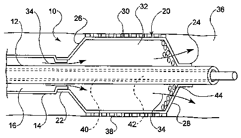
In at least one embodiment, an example of which is shown in FIG. 1, th
invention is directed to a medical device comprising a catheter 10. The
catheter 10
comprises an inner shaft 12 and outer shaft 14 and a balloon 20. The outer
shaft 14 is
disposed about a portion of the inner shaft 12. The radially adjacent portions
of the
shafts 12 and 14 define a lumen 16 therebetween.
The balloon 20 includes a proximal waist 22, a distal waist 24, a
proximal cone 26, a distal cone 28 and a working or body portion 30
therebetween.
When mounted on the catheter 10 the proximal waist 22 of the balloon 20 is
engaged b
a portion of the outer shaft 14 and the distal waist 24 is engaged to a
portion of the innE
shaft 12. As a result of this configuration the interior 32 of the balloon 20
is in fluid
communication with the lumen 16. By transmitting an inflation fluid, indicated
by
arrow 34, under pressure through the lumen 16, the balloon 20 may be expanded
from ;
collapsed and/or folded reduced diameter configuration to an expanded greater
diametc
configuration within a body lumen or vessel 36, such as is shown.
The catheter 10, may be a push catheter, over-the-wire catheter,
MONORAILM catheter, rapid exchange catheter or other type of catheter desired.
In
the embodiment depicted in FIG. 1, the inner shaft 12 defines a second lumen
or
guidewire lumen 40, through which a guidewire 42 is passed. The catheter 10
may thei
be advanced along the guidewire 42 to a predetermined location in the
vesse136.
In some embodiments an expandable endoprosthesis such as a stent 38
may be disposed about the balloon, such that when the balloon 20 is expanded
the stent
is also expanded for delivery into the vessel 36.
As used herein the term 'stent' refers to an expandable prosthesis for
implantation into a body lumen or vessel and includes devices such as stents,
grafts,
stent-grafts, vena cava filters, etc. In some embodiments a stent may be at
least partiallI.
CA 02564628 2006-08-23
WO 2006/002268 PCT/US2005/022120
7
constructed of any of a variety of materials such as stainless steel, nickel,
titanium,
nitinol, platinum, gold, chrome, cobalt, as well as any other metals and their
combinations or alloys. In some embodiments a stent may be at least partially
constructed of a polymer material. In some embodiments a stent may be at least
partially constructed of a shape-memory polymer or material. In some
embodiments a
stent may be balloon expandable, self-expandable, hybrid expandable or a
combination
thereof. In some embodiments a stent or other portions of the catheter may
include one
or more radiopaque members. In some embodiments a stent may include one or
more
therapeutic and/or lubricious coatings applied thereto.
In the embodiment shown in FIG. 1, the distal cone 28 of the balloon 20
defines one or more openings 44 through which the inflation fluid 34 may be
allowed ti
pass from the interior 32 of the balloon 20 out into the vessel 36 distal of
the balloon.
Wlule the openings 44 are configured to allow the inflation fluid 34 to pass
out of the
balloon interior they restrict such outflow to an extent sufficient to allow
the balloon 2(
to build pressure and expand to its expanded configuration despite the loss of
fluid 34
through the openings 44. Openings 44, may be defined as one or more slits,
holes, etc.
having any of a variety of cross-sectional shapes or profiles as may be
desired.
The inflation fluid 34 may be any of a variety of inflation mediums such
as saline (with or without additional therapeutic agents), lactated ringers,
etc. In at leasi
one embodiment the fluid is a liquid. In at least one embodiment the inflation
fluid 34
is also characterized as a coolant, having been cooled to, or having an
inherent
temperature of about 37 degrees Celsius or less. In at least one embodiment
fluid 34 ha
a temperature of about 33 degrees Celsius to about 36 degrees Celsius.
When the fluid/coolant 34 is passed into the balloon interior 32 and morf
significantly directly by outflowing into the vessel 36 via openings 44, the
fluid will
provide a cooling effect to the surrounding tissues of the vessel 36. This
cooling effect
will help to reduce necrosis of the vessel tissue when blood flow is restored
such as by
reopening the vessel by expansion of the balloon 20 and/or placement of a
stent 38.
In some embodiments the fluid 34 comprises a therapeutic agent which
may be passed into the vessel 36 to treat the surrounding tissues as well as
provide the
cooling affect previously mentioned.
In some cases a therapeutic agent may be placed in the balloon interior ol
CA 02564628 2006-08-23
WO 2006/002268 PCTIUS2005/022120
8
inflation lumen in the form of a coating that reacts with or is picked up by
the fluid 34
it flows therethrough. Such an agent may be in the form of a coating that may
also be i
alternatively placed on the balloon exterior and/or the stent. In at least one
embodimer
such a coating includes at least one therapeutic agent and at least one
polymer.
A therapeutic agent may be a drug or other pharmaceutical product sucY
as non-genetic agents, genetic agents, cellular material, etc. Some examples
of suitable
non-genetic therapeutic agents include but are not limited to: anti-
thrombogenic agents
such as heparin, heparin derivatives, vascular cell growth promoters, growth
factor
inhibitors, Paclitaxel, etc. Where an agent includes a genetic therapeutic
agent, such a
genetic agent may include but is not limited to: DNA, RNA and their respective
derivatives and/or components; hedgehog proteins, etc. Where a therapeutic
includes
cellular material, the cellular material may include but is not limited to:
cells of human
origin and/or non-human origin as well as their respective components and/or
derivatives thereof. Where the therapeutic agent includes a polymer agent, the
agent
may be a polystyrene-polyisobutylene-polystyrene triblock copolymer (SIBS),
polyethylene oxide, silicone rubber and/or any other suitable substrate.
While the openings 44 are configured to allow the fluid 34 to pass out o
the balloon 20 when pressurized it is preferable that the openings 44 minimize
or
prevent back flow of fluids, such as blood, from entering the balloon interior
32 from
the vesse136 during the application of negative pressure during
collapse/refold of the
balloon prior to withdrawal of the catheter 10 from the vesse136.
In some embodiments of the invention, the openings 44 may be provide,
with valves, baffles, barriers and/or other mechanisms which permit outflow of
the flui
34 while preventing backflow of the fluid or other bodily fluids.
In at least one embodiment the fluid 34 has a predetermined viscosity
that is less than the viscosity of the blood and/or other fluids typically
present in the
vessel 36. The openings are then sized to allow passage of a fluid having a
viscosity
substantially equal or less than that of the fluid 34 but not fluids having a
greater
viscosity than the fluid 34. In at least one embodiment the openings are sized
and/or
configured to allow fluids having a viscosity similar to that of water and/or
saline to
pass theretbrough, or approximately 1-2 centipoises. In some embodiments the
openings 44 are about 8 microns to about 75 microns in area.
CA 02564628 2006-08-23
WO 2006/002268 PCT/US2005/022120
9
In at least one embodiment, an example of which is shown in FIGs. 2 ai
3, the catheter 10 further comprises an occluding member 46 which is
actuatable
between a collapsed position shown in FIG. 3 and an occluding position shown
in FIG,
2. In at least one embodiment the occluding member is a substantially cone-
shaped
member of flexible material such as polyurethane, SIBS, silicone, Pebax, etc..
The
occluding member 46 has a narrow end region 48 and a wider end region 50. The
narrow end region 48 defines an inner diameter substantially the same as that
of the
inner shaft 12. In at least one embodiment the narrow end region 48 is bonded,
welded
or otherwise engaged to the inner shaft 12 to effectively fix the end region
48 in place
about the inner shaft 14.
When allowed to expand, the wider end region 50 defines an outside
diameter sufficient to expand over and substantially cover the region of the
distal cone
28 which includes the openings 44. In the embodiment show in FIG. 2 the wider
end
region 50 has an outer diameter which is substantially equal to the expanded
inside
diameter of the balloon 20.
When the occluding member 46 is in the expanded state shown in FIG.
the distal cone 28 is occluded from the rest of the balloon interior 32. As a
result, the
flow of fluid 34 to the openings 44 is reduced or eliminated. By varying the
expansion
and size of the occluding member 46 the flow rate of the fluid 34 to and
through the
openings 44 may be regulated as desired.
Several devices may be utilized with the catheter 10 to provide a
mechanism for manipulating the position of the occluding member from the
occluding
position shown in FIG. 2 and the collapsed position shown in FIG. 3. For
example, a
tubular member disposed about the inner shaft 12 and moveable relative
thereto, a
plurality of actuation wires or other elongate member(s) 52 may be connected
to the
occluding member 46 which extend to the proximal end of the catheter (not
shown). B;
pulling the members 52 proximally relative the inners shaft 12 the occluding
member 4
may be pulled toward or into the collapsed position shown in FIG. 3.
Conversely, by
advancing the members 52 distally relative to the inner shaft 12 the wider end
region 5(
of the occluding member 46 may be expanded to occlude the distal cone 28 of
the
balloon 20.
In at least one embodiment the occluding member 46 is provided with a
CA 02564628 2006-08-23
WO 2006/002268 PCT/US2005/022120
bellows which may be configured to elongate down against the inner shaft 12
when the
occluding member 46 is in the collapsed state.
In at least one embodiment, an example of which is shown in FIG. 4, thE
catheter 10 comprises a baffle 54, which is positioned within the interior 32
of the
5 balloon 20, proximally adjacent to the distal cone 28. In some embodiments
the baffle
54 may be positioned distally exteinal of the distal cone 28. The baffle 54 is
an annulai
ring or other member which is disposed about the inner shaft 12, and which
extends
radially outward to engaged the balloon 20 thereby ensuring that its position
within the
balloon interior is maintained regardless of the inflation characteristics of
the balloon.
10 The baffle 54 is constructed of a flexible material which is be capable of
some degree o
expansion and flexing to accommodate the change in balloon shape and size
during
expansion.
The baffle 54 defines one or more baffle openings 56 therethrough. Eac]
baffle opening 54 is positioned on the baffle 54 in such a way so that a given
baffle
opening 56 is longitudinally and/or radially offset from a distally adjacent
balloon
opening 44. As a result of this offset positioning diffusion of the fluid 34
being pushed
out of the balloon openings 44 is improved. Furthermore, when applying
negative
pressure to the balloon 20 during balloon deflation, the offset nature of the
openings 44
and 56 will allow the distal cone 28 and baffle 54 to have a tendency to
occlude the
respective openings therethrough, as the baffle 54 will tend to occlude the
balloon
openings 44 while the distal cone 28 will tend to occlude the baffle openings
54 as the
distal cone 28 collapses against the baffle 54. The baffle 54 may be
constructed of any
of a variety of suitable materials including but not limited to:
polyurethanes, Polyether
block polyamide copolymers (PEBA), SIBS, silicone, polyesters, polyethers,
etc.
In some embodiments a baffle 54 may be provided external of the
balloon 20, such as in the examples shown in FIGs. 5 and 6. Like the interior
baffle
depicted in FIG. 4, an externally mounted baffle may define one or more baffle
openings
therethrough. However, in the embodiments shown in FIGs. 5 and 6 rather than
define
openings through the material of the baffle 54, the baffle 54 is fixedly
engaged along
only one end region 56 to the balloon 20 (in the embodiment depicted in FIG.
5) and/or
to the inner shaft 12 (in the embodiment depicted in FIG. 6).
By providing the catheter 10 with an external baffle 54 which is engaged
CA 02564628 2006-08-23
WO 2006/002268 PCT/US2005/022120
11
to balloon 20 or shaft 12 in this manner, the baffle acts as a one way flap or
valve, whic
permits the exit of fluid 34 from the balloon interior 32, but which limits or
prevents
entrance of bodily fluid such as blood, indicated by arrow 35, from entering
the balloon
during deflation. When the balloon 20 is expanded by injecting fluid 34 into
the interic
32 of the balloon via lumen 16, the pressure is sufficient to expand the
balloon and also
eject some fluid 34 from the balloon through the openings 44. The pressure
exerted by
the fluid 34 against the baffle 54 is sufficient to lift the free end 58 of
the baffle off of
the distal cone 28 to allow the fluid 34 to pass out of the catheter 10.
During deflation
of the balloon 20, negative pressure is applied to the balloon, such as by
vacuum
through the lumen 16. Such a negative pressure will tend to pull the free end
58 of the
baffle 54 against the distal cone 28, thereby forming a fluid tight seal over
the openings
44.
In some embodiments the catheter 10 may be configured to avoid the us
of openings in the balloon 20 to permit flow of fluid 34 distally out of the
catheter. For
example, in the embodiment shown in FIG. 7, the balloon interior 32 is in
fluid
communication with the guidewire lumen 40 through one or more openings or
entrance
ports 60 through the inner shaft 12. Thus a fluid path is provided, which
allows fluid 3~
which is transmitted through the inflation lumen 16 and into the balloon
interior 32 to
pass through the shaft entrance port 60 and into the guidewire lumen 40.
The guidewire lumen 40 and/or the guidewire 42 may be sized or
otherwise configured to prevent and/or limit the flow of fluid 34 from
entering the
lumen 40 while the guidewire 42 is positioned across the port 60. By
withdrawing the
guidewire 42 proximally to unblock the port 60 the fluid 34 is free to enter
the
guidewire lumen 40.
Once the fluid 34 is in the guidewire lumen 40 the fluid 34 is able to
travel through the lumen 40 and out the opening 64 at the distal end 66 of the
inner shafi
12. In some embodiments a valve mechanism may be positioned in the distal
portion to
prevent fluid from entering the lumen 40.
In some embodiments the inner shaft defines at least one exit port 68
through which the fluid 34 may exit the guidewire lumen 40. One or more exit
ports 68
may be provided to alter the diffusion and/or direct the fluid 34 as it leaves
the catheter
10.
CA 02564628 2006-08-23
WO 2006/002268 PCT/US2005/022120
12
In many catheter assemblies the guidewire lumen is typically open at
both the distal end and proximal end of the catheter to allow the guidewire to
pass freel,
therethrough. However, because the guidewire lumen 40 in this case is
configured to
transmit fluid 34 therethrough, the lumen at one or more points may include
one or moi
valves, flaps, regulators or other flow regulating devices, herein after
referred to
collectively as valve mechanism(s) and depicted by reference numera162, which
allow
the guidewire 42 to pass therethrough but which provide a fluid seal in at
least one
direction to the lumen 40. For example, in at least one embodiment at the
proximal end
portion 70 of the lumen 40 a valve mechanism 62 may be provided which acts as
a fluic
static valve to prevent fluid 34 from exiting the catheter proximally
therethrough, but
which allows the guidewire 42 to freely pass. Additionally or alternatively, a
one way
valve mechanism 62 may be provided distal of the shaft entrance port 60 which
is
configured to permit the outflow of fluid 34 but prevents and/or limits bodily
fluid such
as blood from entering the balloon during deflation.
In at least one embodiment, an example of which is shown in FIG. 8, the
catheter 10 comprises a single shaft 12, similar in configuration to the inner
shaft
previously described in FIG. 7, about which the balloon 20 is mounted. The
single shaf
12 includes one or more shaft entrance ports 60 and exit ports 68 to allow the
balloon
interior 32 and the guidewire lumen 40 to be in fluid communication such as in
the
manner described above. The shaft 12, and more significantly the guidewire
lumen 40
defined by the shaft have a proximal portion 72 and a distal portion 74.
The proximal portion 72 is configured so that the inner diameter of the
shaft 12 (i.e. guidewire lumen 40) is greater than the inner diameter of the
distal portion
74. In at least one embodiment the distal portion 74 has an inner diameter of
about
0.015 inches to about 0.020 inches, whereas the proximal portion 72 has a
greater inner
diameter of about 0.028 inches to about 0.032 inches. In at least one
embodiment the
inner diameter of the distal portion 74 is about 0.017 inches.
The proximal portion 72 is sized, such that when the guidewire 42 is
present within the proximal portion 72 of the lumen 40 a space is maintained
between
the shaft 12 and the guidewire 42 which also functions to provide a lumen
through
which the fluid 34 may be transported.
The guidewire 42 and the distal portion 74 of the lumen 40 are of a
CA 02564628 2006-08-23
WO 2006/002268 PCT/US2005/022120
13
complementary diameter size, which is less than that of the proximal portion
72, such
that when the guidewire 42 is passed into the distal portion 74 of the
guidewire lumen
40, there is insufficient space to provide adequate flow of the fluid into the
distal portio
74. By removing the guidewire proximally from the distal portion 74, the
distal portion
of the lumen 40 becomes unobstructed to the flow of fluid 34 as depicted in
FIG. 8. In
some embodiments a valve mechanism may be provided distally of the fluid
entrance
port 60, within or external to the lumen 40 to regulate pressure in the
balloon interior 3:
and flow of the fluid 34 out of the catheter 10.
In the various embodiments discussed thus far, the catheter 10 employs z
fluid 34 which acts to inflate the balloon 20 as well as act as an infusate or
coolant
medium that is diffused distally out of the catheter 10. As indicated above,
however
configurations of the catheter 10 which accommodate a single
inflation/infusate fluid 3z
may require the use of various ports, valve mechanisms and/or other devices
such as
baffles to properly diffuse the fluid and to prevent backflow of bodily fluids
during
balloon collapse. In some embodiments however, the catheter may be configured
with
an inflation lumen which is separate and distinct from an infusate or coolant
lumen.
These embodiments may avoid the need for many of the flow regulating
mechanisms
previously described.
In at least one other embodiment, an example of which is illustrated in
FIG. 9, the catheter 10, may have the balloon mounting configuration using an
inner
shaft 12 distally and an outer shaft 14 proximally, such as that previously
shown and
described in FIG. 1. However, the catheter 10 shown in FIG. 9 also includes an
outer
sheath 90. The outer sheath 90 effectively forms the outer perimeter of a
dedicated and
separate infusate lumen 82 whereas, moving proximally to distally, the outer
shaft 14,
the balloon 20 and optionally the inner shaft 12 defines the inner perimeter
of the
infusate lumen 82.
The addition of the sheath 90 may be used on a wide variety of existing
catheter assemblies to provide the catheter with a coolant delivery mechanism.
The above disclosure is intended to be illustrative and not exhaustive.
This description will suggest many variations and alternatives to one of
ordinary skill in
this art. The various elements shown in the individual figures and described
above may
be combined or modified for combination as desired. All these alternatives and
CA 02564628 2006-08-23
WO 2006/002268 PCT/US2005/022120
14
variations are intended to be included within the scope of the claims where
the term
"comprising" means "including, but not limited to". Those familiar with the
art may
recognize other equivalents to the specific embodiments described herein which
equivalents are also intended to be encompassed by the claims.
Further, the particular features presented in the dependent claims can be
combined with each other in other manners within the scope of the invention
such that
the invention should be recognized as also specifically directed to other
embodiments
having any other possible combination of the features of the dependent claims.
For
instance, for purposes of claim publication, any dependent claim which follows
should
be taken as alternatively written in a multiple dependent form from all prior
claims
which possess all antecedents referenced in such dependent claim if such
multiple
dependent format is an accepted format within the jurisdiction (e.g. each
claim
depending directly from claim 1 should be alternatively taken as depending
from all
previous claims). In jurisdictions where multiple dependent claim formats are
restrictec
the following dependent claims should each be also taken as alternatively
written in
each singly dependent claim format which creates a dependency from a prior
antecedent-possessing claim other than the specific claim listed in such
dependent clain
below.
This completes the description of the preferred and alternate
embodiments of the invention. Those slcilled in the art may recognize other
equivalents
to the specific embodiment described herein which equivalents are intended to
be
encompassed by the claims attached hereto.
This PCT application claims priority from US Application No.
10/875,560, filed on June 23, 2004, the entire contents of which is hereby
incorporated
by reference.