Note : Les descriptions sont présentées dans la langue officielle dans laquelle elles ont été soumises.
CA 02565952 2006-11-15
VEHICLE WASH APPARATUS WITH AN ADJUSTABLE BOOM
10 FIELD OF THE INVENTION
The present invention relates generally to automatic vehicle washing systems
and,
more particularly, to an overhead cleaning platform capable of independent
vertical and
pivotal positioning of a plurality of nozzles attached thereto.
BACKGROUND OF THE INVENTION
"Brushless" automated vehicle washing systems are commonly utilized to quickly
and efficiently clean vehicles without requiring any hand scrubbing or contact
between
cleaning members and the exterior of a vehicle. Brushless vehicle washing
systems utilize
jets of pressurized cleaning fluid sprayed from a plurality of nozzles to wash
away dirt and
grime from the exterior surfaces of a vehicle. In one common type of washing
system, the
nozzles are commonly arranged in a gantry. The gantry either 1) passes over
and around the
vehicle or 2) is stationary and the vehicle passes through it. In either
instance, the nozzles
direct jets of cleaning fluid over most if not the entire exterior surface of
the vehicle.
The cleaning efficiency and effectiveness of a vehicle washing system is
largely
dependent upon two factors: the force at which the pressurized cleaning fluid
impinges on
the vehicle surface; and the effective area on the vehicle's surface impacted
by the
pressurized cleaning fluid. In order to effectively clean the entire surface
of a vehicle, the
cleaning fluid jet must impact the adjacent surface with a requisite amount of
force in order
to dislodge any dirt or foreign matter resident on the adjacent surface. The
amount of force
per unit area imparted on the adjacent surface is dependent on several factors
including the
CA 02565952 2006-11-15
speed and angle at which the jet of cleaning fluid impacts the adjacent
surface. As the
distance between the nozzle and the adjacent surface increases, the speed of
the cleaning
fluid decreases; also the jet begins to fan increasing the impact area on the
adjacent surface,
thereby spreading the impact force over a greater area, and reducing cleaning
effectiveness.
Accordingly, those parts of a vehicle that are furthest from the nozzles may
not be
adequately cleaned.
Typically, gantry-type cleaning systems have the most difficulty cleaning the
front
and rear of a vehicle, since the nozzles located at the sides and top of the
gantry normally
direct jets of cleaning fluid parallel or at a very shallow angle to the
vehicle's front and rear
surfaces. Gantry-type washing systems have been developed wherein overhead
nozzles are
mounted on moveable platforms that (1) pivot to increase the angle of
incidence between the
fluid jet and the front and rear surfaces of the vehicle, (2) move vertically
to decrease the
distance between the nozzles and front and rear surfaces, or (3) both pivot
and move
vertically. The last type of moveable platform is preferred, wherein the
platform maybe
lowered to get close to front or rear surfaces and pivoted so that the fluid
jets impact the
surface at a desired angle.
Despite what type of vehicle washing system is utilized, vehicle owners often
desire
the option of applying additional specialty solutions to their vehicle, such
as spot free rinse
solutions and clear solutions. Both of these solutions are relatively
expensive when
compared to the other liquids used during the wash cycle such as water.
Accordingly, it is
desirable to minimize waste of the specialty solutions, while maximizing
coverage of the
vehicle's surface. Current art gantry-systems apply these solutions in a
number of ways.
Using one method, specialty solutions may be applied through the same high-
pressure
nozzles that are utilized to apply the cleaning and rinsing solutions. This is
undesirable for
at least two reasons: one, the specialty solution left in the supply lines
must be purged prior
to the beginning of the next vehicle wash; and two, the use of a high pressure
delivery
device might deliver a greater than necessary volume of specialty solution to
the vehicle as
the gantry traverses the vehicle's length. The result is an inefficient use of
the expensive
specialty solutions. It is noted that high-pressure delivery of specialty
fluid is rarely
necessary since specialty solutions are chemical cleaners, not dynamic
cleaners;
2
CA 02565952 2006-11-15
accordingly, the primary goal when applying a specialty solution is simply to
obtain
complete vehicle coverage.
Another method utilized to apply specialty solutions has been to spray the
specialty
fluid, often in the form of a foam, onto the sides of the vehicle from
discharge openings
spaced along vertical dispensing tubes attached to the gantry's side legs. The
problem of
inefficiency is minimized, since there is no need to purge the dedicated
specialty fluid
delivery system after each vehicle wash. Unfortunately, these vertically
mounted delivery
systems have difficulty in delivering solution in a manner that completely
covers the top
surfaces of a vehicle as there is often little impetus for the applied
specialty solution to flow
along the horizontal top surfaces of the vehicle, especially when the solution
is in the form
of a foam.
SUMMARY OF THE INVENTION
An automatic vehicle washing system is described. In one embodiment, a
vertically
moveable platform is suspended from a left end while being supported from
below on the
right end. One or more nozzles are coupled with the platform for spraying jets
of cleaning
fluid onto the surface of a vehicle. Preferably, the left end of the platform
is suspended by a
belt, cable or chain wherein the belt, cable or chain is slideably coupled to
the frame and
ultimately connected to the right end of the platform for uniform vertical
movement
therewith. The right end of the platform is supported by a lift actuator.
Accordingly, when
the lift actuator is actuated to lift the right end of the platform, the belt,
cable or chain slides
through the frame coupling and is pulled upwards at its junction with the left
end, causing
the left end to rise in unison with the right end.
In a preferred embodiment, the lift actuator is pneumatic and in communication
with
a compressor to provide the pressurized air necessary to lift and lower the
platform. A
pressurized air tank may be provided to serve as a backup in case of a power
failure or car
wash system malfunction. The air tank may be coupled to a pneumatic switch
which
automatically opens and allows pressurized air into the lift actuator to raise
the platform to
its topmost position should power to the compressor be interrupted. In other
embodiments,
CA 02565952 2006-11-15
a mechanical lift actuator that uses a lead screw, a drive screw or a drive
belt may be used in
place of a pneumatic lift.
Typically, the platform comprises a pivoting boom attached to a reciprocating
pivotal actuator. A plurality of cleaning nozzles are coupled with the boom
and by pivoting
S the boom; the angle of the fluid jets emanating from the nozzles can be
changed. In a first
variation of the pivoting boom, mechanical stops are utilized to set the
clockwise and
counterclockwise pivoted positions of the boom, thereby varying the angle of
the fluid jets
off vertical. In a second variation of the pivoting boom, the actuator is
utilized in
conjunction with a guided follower arm. The follower arm permits a certain
amount of
pivotal movement of the boom depending on the vertical location of the
platform. In a third
variation of the pivoting boom, the actuator is capable of pivoting to a
plurality of selected
orientations and holding the boom at that orientation. As necessary, sensors
are utilized to
determine the desired pivotal orientation of the boom.
The nozzles may be coupled to the boom in any suitable fashion, although in
one
1 S embodiment the nozzles are coupled to the boom by way of rotating wand
assemblies
wherein the nozzles are attached to the ends of one or more wands. In another
embodiment,
nozzle-tipped wands may reciprocate about a pivot point on the boom. The
nozzles may
also be directly attached to the boom. The nozzles may be 0-degree nozzles,
turbo nozzles,
slow rotating turbo nozzles, oscillating nozzles or any other type, or
combination thereof. In
the preferred embodiment, the boom nozzles are fluidly coupled with a dump
valve that is
typically located below the boom at a location approximately 3 feet from the
base of the
vehicle wash framework with a hose extending from the dump valve to the floor
of the wash
bay. In operation after a wash cycle has been performed, the dump valve is
activated and a
substantial portion of the cleaning solution remaining within the nozzles is
siphoned out of
the system therethrough.
In the preferred embodiment, one or more low pressure fluid conduits with low
pressure nozzles attached thereto are attached to a bottom surface of the
horizontal span of
the gantry, wherein specialty fluids such as clear coats and spot free rinses
may be sprayed
on the top of the vehicle. Additionally, low-pressure fluid conduits may be
provided on
either leg of the gantry to spray the fluids onto the side of the vehicle. By
providing a low-
4
CA 02565952 2006-11-15
pressure conduit for each specialty fluid, the conduits need not be flushed to
change fluids.
Furthermore, by utilizing specialized individual conduits, specialty fluid
efficiency is
enhanced. The overhead and side locations of the conduits ensures accurate and
adequate
application of fluid to all surfaces of the vehicle. In one embodiment, clear
coat (or drying
agent) conduits are located proximate either the front or rear face of the
gantry and spot free
rinse (or reverse osmosis water) conduits are located proximate the other of
the front or rear
face of the gantry, wherein both specialty solutions can be applied in a
single pass of the
gantry over the vehicle.
In the preferred embodiment a series of turbo nozzles are located on the
inside
surfaces of the gantry legs. The nozzles are located at vertical positions
generally
corresponding to the locations of a rocker panel on a vehicle, the middle of a
vehicle and the
upper portion of a vehicle. Typically, the plurality of nozzles in each leg
are supplied high
pressure fluid from a common source and are capable of concurrent operation.
One or more
solenoids or switches may be provided wherein the nozzles corresponding to the
upper or
lower portions of the vehicle may be turned on or off independently of the
other nozzles.
The integration of the rocker panel nozzles and the side nozzles to the same
fluid source
permit both a side rinse and rocker panel blast to occur in the same pass.
The integration of the boom nozzles with the upper and lower side nozzles on
the
gantry legs or the preferred embodiment facilitates pressure profiling of the
vehicle during
the wash cycle. The pressure of cleaning solution supplied to the nozzles is
greatest when
only the boom nozzles are being utilized to clean the front and reax ends of
the vehicle. The
cleaning solution pressure is at a medium level when the boom nozzles are
being utilized in
conjunction with the lower side nozzles of the gantry legs to clean the hood
or trunk and the
sides of the vehicle proximate the hood or the trunk. The cleaning solution
pressure is at its
lowest when the boom nozzles and the upper and lower side nozzles of the
gantry legs are
all utilized simultaneously to clean the cab of the vehicle.
In the preferred embodiment of the invention, a moving gantry is utilized that
moves
over and alongside a stationary vehicle on a set of rails. A gear motor is
utilized that can
move the gantry at a plurality of speeds along the rails. The motor is
interfaced with a
microprocessor controller. Through the controller, which measures the gantry's
movement
5
CA 02565952 2006-11-15
along associated rails through a pulsar wheel and sensor, the gantry's rate of
travel over the
vehicle can be varied not only from pass to pass but responsive to various
zones identified
on the vehicle that is being washed. When the boom is deployed in front of or
behind the
vehicle, the controller is further configured to override the set speed for
the associated zone
as necessary to ensure that the boom does not come into contact with the
vehicle.
Other aspects, features and details of the present invention can be more
completely
understood by reference to the following detailed description of the preferred
and selected
alternative embodiments, taken in conjunction with the drawings, and from the
appended
claims.
BRIEF DESCRIPTION OF THE DRAWINGS
Figure 1 is a front elevation of a gantry-type washing system with an
automobile
positioned in-between the gantry.
Figure 2 is a fragmentary section taken along line 2-2 of Figure 1.
1 S Figure 3 is a fragmentary section taken along line 3-3 of Figure 1.
Figure 4 is an enlarged section taken along line 4-4 of Figure 1.
Figure 5 is a fragmentary section taken along line 5-5 of Figure 2 & 3.
Figure 6 is an enlarged fragmentary section taken along line 6-6 of Figure 5.
Figure 7 is a section taken along line 7-7 of Figure 6.
Figure 8 is a section similar to Figure 7 with components in a different
position.
Figure 9 is a fragmentary isometric of the pivoting boom assembly.
Figure 10 is a fragmentary isometric illustrating the left end of the pivoting
boom
assembly.
Figure 11 is a fragmentary isometric illustrating the right end of the
pivoting boom
assembly.
Figure 12 is a fragmentary isometric of the pivoting moveable platform
illustrating
the downward vertical movement of the boom and the operation of the rotating
wands.
Figure 13 is a fragmentary isometric of the pivoting moveable platform similar
to
Figure 12 illustrating the orientation of the pivoting boom after a clockwise
rotation.
6
CA 02565952 2006-11-15
Figure 14 is a fragmentary isometric of the pivoting moveable platform similar
to
Figure 12 illustrating the orientation of the pivoting boom after a
counterclockwise rotation.
Figure 15 is a fragmentary isometric of a portion of a first alternative
pivoting
moveable platform that utilizes reciprocating wands and turbo nozzles in place
of the
rotating wands.
Figure 16 is a fragmentary top plan view illustration of the alternative
pivoting
moveable platform showing the spray pattern of the turbo nozzles.
Figure 17 is a fragmentary top plan view illustration of the first alternative
pivoting
moveable platform showing the range of reciprocating movement of the wands.
Figure 18 is a section taken along line 18 - 18 of Figure 16.
Figure 19 and 20 are fragmentary isometric views looking at the outside and
inside
respectively of the left leg of the gantry in an alternative tilting
mechanism.
Figure 21 is top view of the bay of a vehicle wash system illustrating the
wheel stops
and vehicle guide members.
Figure 22 is an enlarged isometric view of the wheel stop and the guide
platform of
the outside vehicle guide member.
Figure 23 is an enlarged fragmentary section taken along lines 23-23 of Figure
2
illustrating a series of turbo nozzles.
Figure 24 is an enlarged section similar to Figure 4 illustrating a variation
in the
configuration of the low pressure delivery tubes.
Figures 25 and 26 are side views of one leg of the gantry with cut away
portions
illustrating a pivoting boom centering mechanism according to one variation of
the present
invention.
Figure 27 is a fragmentary isometric of a portion of a variation of the first
alternative
moveable platform that utilizes reciprocating wand attached to a twin tube
boom.
Figure 28 is a fragmentary isometric of a portion of another variation of the
first
alternative moveable platform that utilizes reciprocating wand attached to a
twin tube boom.
Figures 29 and 30 are fragmentary isometrics of a portion of a second
alternative
pivoting moveable platform that utilizes turbo nozzles attached directly to a
twin tube boom
in place of the rotating or pivoting wand assemblies.
7
CA 02565952 2006-11-15
Figures 31 and 32 are sectional views of the second alternative pivoting
moveable
platform taken along lines 31-31 and 32-32 of Figures 29 and 30 respectively.
Figure 33 is a flow diagram illustrating the operations performed during a
four pass
vehicle wash cycle.
Figure 34 is vertical section of a turbo nozzle.
Figure 35 is an isometric view of a rotating nozzle member of a turbo nozzle.
Figure 36 is a section of the rotating nozzle member taken along line 36-36 of
Figure
35.
Figure 37 is a section of the turbo nozzle taken along line 37-37 of Figure
34.
Figure 38 is a section of the rotating turbo nozzle taken along line 38-38 of
Figure
34.
Figure 39 is a section of the turbo nozzle taken along line 39-39 of Figure
34.
Figure 40 is a section similar to Figure 39 illustrating a variation of the
rotating
nozzle member at line 39-39.
Figure 41 is a partial section of a prior art fast rotating turbo nozzle taken
along lines
36-36 of Figure 34 having a single inlet orifice into the nozzle body.
Figure 42 is a partial section of a slow rotating turbo nozzle taken along
lines 36-36
of Figure 34 having four inlet orifices into the nozzle body.
Figure 43 is a exploded isometric view of an oscillating nozzle.
Figure 44 is a fragmentary isometric of an oscillating nozzle showing atypical
spray
pattern of an oscillating nozzle
Figure 45 is a side view of a vehicle segmented into three zones illustrating
the path
of the overhead nozzles during a wash cycle.
Figure 46 is a block diagram of a vehicle washing system's controller
interfaced with
the vehicle washing system's sensors and drive mechanisms.
DETAILED DESCRIPTION
A gantry-type vehicle washing system in accordance with the present invention
incorporates a single pneumatic cylinder to lift and lower both sides of an
overhead cleaning
platform in cooperation with a drive belt, eliminating the need to coordinate
movement
8
CA 02565952 2006-11-15
between two lifting mechanisms located on either ends of the platform. The
platform
includes a reciprocating pivotal actuator that is coupled with a boom such
that the boom can
be pivoted. A plurality of fluid delivery nozzles are coupled to the boom.
Advantageously,
the pivotal movement of the boom is operationally independent from the
vertical movement,
thus permitting greater adaptability of the washing system to vehicles of
differing profiles.
Furthermore, one or more low-pressure conduits are disposed lengthwise across
the top span
of the gantry and vertically along the legs of the gantry with nozzles spaced
thereon to
deliver specialty fluids to the top and sides of the vehicle. Nozzles located
near the end of
the manifolds may be angled inwardly slightly as to insure the specialty
fluids impact the
vehicle. One set of conduits for a first type of fluid, such as a clear coat,
may be located
near one face of the gantry and another set of conduits for a second type of
fluid, such as a
spot free rinse, may be located near the other face of the gantry.
Advantageously, during a
single pass of the gantry over the vehicle, the first type of fluid may be
applied to the vehicle
as the one face passes overhead, and the second type of fluid applied to the
vehicle as the
other face passes overhead shortly thereafter. Finally, a switch or solenoid
is provided,
wherein the fluid supply to the upper high pressure nozzles on each gantry leg
can be shut
off without interrupting the fluid supply to the lower high pressure nozzles.
Additionally,
another switch or solenoid is provided wherein both the upper and lower
nozzles on a gantry
leg can be turned off during a wash cycle while the high pressure nozzles
associated with the
moveable platform can continue to operate. Accordingly, depending on the
profile of the
vehicle being washed, the upper nozzles can be turned off when their fluid
jets would not
impact the side of the vehicle and both the upper and lower nozzles can be
turned off when
the gantry is in front of or behind the vehicle such as when the front or rear
surfaces of the
vehicle are being washed.
A First Embodiment
A first embodiment of a gantry type vehicle washing system 100 in accordance
with
the present invention is illustrated in Figures 1-14 and 21-26.
Referring to Figure 1, the gantry type vehicle washing system 100 comprises a
gantry structure 105, gantry guide rails 110, and vehicle guide members 112.
Generally, the
gantry structure 105 includes the plumbing and mechanicals necessary to
effectively clean a
9
CA 02565952 2006-11-15
vehicle 120, such as an automobile, truck, van or SUV, as will be described in
detail herein.
In the preferred embodiment, the gantry structure 105 moves reciprocally along
the length of
a vehicle on gantry guide rails 110. Rail wheels and a gear motor (neither
shown) are
contained within the gantry structure 105 to propel it back and forth. A
preferred
embodiment of the gantry also includes an idler wheel (not shown) that is in
contact with the
rail and coupled with a pulsar wheel and associated sensor (neither shown).
The pulsar
wheel sensor is coupled to the controller to provide the controller with
signals concerning
the rate of travel of the gantry. In the preferred embodiment, the gear motor
is also coupled
to the controller and is adapted to propel the gantry structure 105 at a
plurality of selectable
speeds (0.33 to 1.52 feet/second) along the rails. It is to be understood that
in alternative
embodiments, movement of the gantry structure relative to the vehicle being
cleaned could
be accomplished in any conceivable manner with or without the use of rails 110
that would
be obvious to one of skill in the art. For instance, automobile 120 may merely
drive through
a fixed and stationary gantry structure. In another instance, the gantry 105
could be
suspended from a ceiling and slide or roll along guides provided therein.
Vehicle guide
members 112 are also provided to help the driver of a vehicle properly
position the vehicle
under the gantry 105, at a proper distance from the sides of the gantry 105.
An example of a
gentry structure of the general type described is shown in United States
Patent No.
5,076,304 which is of common ownership with the present : invention. ,
As illustrated in Figures 21 and 22, inside and outside vehicle guide members
112,
113 and 114 are provided. The left and right outside guide members comprise
both raised
tubes 112 that run generally parallel to the gantry guide rails 110 and a
guide platform 113
disposed on the inside of the raised tubes 112 that has inside vertical
surfaces that are angled
inwardly towards a set of front tire stops 115. A vehicle 120 enters the car
wash by driving
between the raised tubes 112. If the vehicle 120 approaches the front tire
stops 11 S too far
to one side, the inside vertical surface of one of the guide platforms 113
impacts the outside
of the vehicle's front tire and guides the vehicle 120 towaxds the tire stops
115. The inside
guide member 114 comprises a generally V-shaped raised tubular structure that
is centered
relative to the inside surfaces of the left and right legs of the gantry with
the vertex of the
CA 02565952 2006-11-15
"V" facing the vehicle wash entrance. Accordingly, if the vehicle 120 strays
to the left or
right as it approaches the tire stops 115, the inner guide member 114 impacts
the inside of
the vehicle's front tire and guides the vehicle back towards a center
position. As can be
appreciated, the shortest distance between the vertical surfaces of the outer
guide member's
guide platform 113 must be greater than the widest track of the type of
vehicle the vehicle
wash is designed to service.
In a prior art wash system with only an outside guide member, a vehicle with a
small
track width can be positioned within the wash in such a manner such that the
distance
between the nozzles on one leg of the gantry and one side of the vehicle is
much smaller
than the distance between the nozzles on the other leg and the other side of
the vehicle. The
inside guide member 114 has a maximum width at the opening of the "v" shape
that is
smaller than the shortest distance between the inside surfaces of the tires on
a vehicle having
the smallest track that the vehicle wash system is designed to service.
Advantageously, a
vehicle with a small track width that is too far to the left or the right upon
entering the
vehicle wash will be guided by the inside guide member towards a center
position between
the left and right legs of the gantry, thereby minimizing the difference in
distances between
the side nozzles and the respective side surfaces of the vehicle.
Referring again to Figure 1, the typical gantry structure 105 is in the form
of an
inverted-U having a left leg 205, a right leg 210, and a top span 21 S.
Located along the front
side of the gantry structure 105 is a dryer apparatus 220 designed to blow
high velocity air
onto a vehicle as the gantry 105 moves along and over the vehicle after the
wash cycle has
been completed. The high velocity air is generated by one or more fans (not
shown)
contained within the dryer apparatus housing and blown through ducting 222 and
out vents
224 located on the three inside surfaces of the gantry 105. Alternative
embodiments of the
washing system 100 may not incorporate a dryer apparatus 220 or the apparatus
220 may be
separate from the gantry structure 105.
Refernng to Figures 2 & 3, a plurality of turbo nozzles 230 are distributed on
the
inside surface of the left and right legs 205 & 210 of the gantry structure
105 and are located
in a vertical line between the front and rear of each of the legs in the lower
portion of the
legs corresponding generally to the side surfaces of a vehicle. The advantages
of turbo
11
CA 02565952 2006-11-15
nozzles over traditional 0 degree nozzles will be discussed in detail infra.
Suffice it to say,
the fluid j et from each turbo nozzle more effectively cleans a given area of
the vehicle
surface than traditional nozzles, thereby either reducing (1) the number of
nozzles required
or (2) the need to have the nozzles attached to rotating wand assemblies. It
is to be
appreciated that both turbo nozzles and traditional zero degree nozzles as
described herein
are high pressure nozzles wherein fluids supplied to these nozzles are under
pressures
typically in excess of 500 pounds per square inch (psi) to upwards of 1000
psi. The high
pressure nozzles are typically utilized in a vehicle wash to supply a cleaning
solution, which
is typically soft water, to the surface of the vehicle in such a manner that
the dirt and debris
is dynamically removed from the vehicle's surface.
A preferred configuration of the plurality of turbo nozzles 230, as
illustrated in
Figure 23, comprises several rocker panel blaster nozzles 230A, several middle
nozzles
230B for cleaning the side of the automobile and several upper nozzles 230C
for cleaning
the sides of the body that are typically vertically located above the hood.
The rocker panel
1 S Masters 230A are typically high volume turbo nozzles that can effectively
dislodge the types
of debris, such as mud, that can accumulate on the rocker panels of a vehicle
between
washes. The middle and upper turbo nozzles 230B and 230C typically spray a
lower volume
of solution than the rocker panel blasters 230A since the middle and upper
portions of a
vehicle typically do have as much debris on them as the rocker panels.
Generally, the
plurality of turbo nozzles 230 located in each leg 105 of the gantry are
connected in series to
a manifold 236 and are turned on or off through a solenoid valve 237 located
at the base of
the manifold proximate a location where the manifold joins the solution supply
line.
Accordingly, the control system can control the supply of solution to the
plurality of nozzles
230 depending on the operation being performed during a particular wash cycle.
Additionally, a second solenoid valve 238 is provided along the manifold 236
between the
middle and upper nozzles 230B and 230C such that the control system can turn
the flow of
solution to the upper nozzles 230C off or on depending on the location of the
gantry relative
to the side of a vehicle. Accordingly, the upper nozzles 230C can be turned
off when the
gantry is traveling over the hood or trunk of the vehicle since the jets
emanating from these
12
CA 02565952 2006-11-15
nozzles would not impact the side of the vehicle or could be turned on when
traveling over
the cabin of the vehicle which is higher on the sides.
A variation of the plurality of turbo nozzles 230 is contemplated wherein a
third
solenoid valve is specified to selectively control the flow of cleaning
solution to the rocker
panel blasters independent of both the middle and upper nozzles. It is to be
appreciated that
although the series of nozzles described herein are connected to a manifold in
series, each of
the sets of rocker panel, middle and upper nozzles can be attached to the
manifold or
multiple manifolds in parallel as would be appreciated by someone of ordinary
skill in the
art with the benefit of this disclosure.
Additionally, referring to Figures 2 and 3, several low pressure presoak
solution
nozzles 242 are distributed on the inner surface of the legs and the top span.
These nozzles
are typically configured to spray a detergent solution onto the vehicle as the
gantry 105
passes over it. The key consideration in locating the presoak nozzles 242 is
to insure that
the vehicle can be completely covered in presoak solution. The relative force
per area at
which the presoak solution impacts the surface of the automobile is generally
not important.
Low pressure nozzles, such as the presoak nozzles and specialty solution
application nozzles
(as will be described below), typically operate at pressures between SO and
150 psi.
Variations of the invention may incorporate any number of different
configurations of side
nozzles to perform both the presoak and wash cycles as would be obvious to one
of skill in
the art with the benefit of this disclosure.
Figure 4 is a view looking up at the inside of the top span 21 S. Two low-
pressure
fluid delivery tubes 235 (or manifolds) are located proximate the front and
rear sides of the
top span 215. Each of.the fluid delivery tubes 235 is in operative connection
with a reservoir
of specialty fluid and a low-pressure pump (both not shown). Several low-
pressure nozzles
237 & 239 are distributed on each of the low-pressure fluid delivery tubes 235
to spray
specialty solutions, such as a clear coat, a soft water rinse or a spot free
rinse (using reverse
osmosis water) onto a vehicle. As with the application of presoak solution,
the primary
concern in applying a clear coat is obtaining complete coverage of the surface
of a vehicle
with relatively little concern regarding the force at which the solution
impacts the surface
when compared to dynamic application of cleaning solution by the high pressure
nozzles.
13
CA 02565952 2006-11-15
Although still low pressure nozzles, the spot free rinse is typically applied
at slightly higher
pressures (around 100 psi) using nozzles that have a greater volumetric
capacity than the
clear coat nozzles in order to induce a "squeegee" effect to ensure complete
coverage of the
vehicle. The low pressure nozzles 237 located proximate the intersection
between the inner
surface of the left and right legs and the inside of the top span may be
angled inwardly
towards the side surfaces of the vehicle so that the specialty solution is
sprayed thereon.
Depending on the embodiment, additional specialty solution nozzles maybe
located on the
inside of the right and left legs 205 & 210 to insure complete coverage of the
side surfaces.
Although two low-pressure fluid delivery tubes 235 are shown, it is understood
that
alternative wash systems may have more or fewer low-pressure fluid delivery
tubes 235
located on the inside of the top span 215.
In a variation of the low pressure delivery tubes, as shown in Figure 24, a
clear coat
or drying agent delivery tube 235A is located proximate the front or rear edge
of the top
span 215, as well as, the corresponding edge of the legs 205 & 210, and a spot
free rinse
(using reverse osmosis water) or soft water delivery tube 235B is located
proximate the
opposite edge of the top span 215. In operation, as the gantry passes over the
vehicle, the
clear coat or drying agent is first applied to the surface of the vehicle and
has time to soak
until the other edge of the gantry passes overhead and the spot free rinse
(reverse osmosis
water) or soft water solution is applied to the vehicle. Advantageously, the
application of
both specialty fluids can be performed in a single pass instead of two passes
that would
typically be required using prior art vehicle wash systems.
Again refernng to Figure 4, as well as, Figures S & 9, a moveable platform 240
is
located at the proximate front-to-rear center of the inside or bottom of the
top span 215 and
is substantially coextensive with the top span 215. The moveable platform 240
comprises:
(1) a pivoting boom 245; (2) two rotating wand assemblies 250 attached to the
pivoting
boom 245; (3) a reciprocating rotary pivotal actuator 260 pivotally attached
to the pivoting
boom 245; and (4) a mounting system to secure the moveable platform 240 to the
gantry
105.
The rotating wand assemblies 250 each typically comprise three hollow wands
252
radiating from a rotating manifold 254. Each wand 252 is adapted to carry
pressurized
14
CA 02565952 2006-11-15
cleaning fluid therein and one or two zero-degree nozzles 256 are generally
attached to its
distal ends. In other variations, an oscillating nozzle or a turbo nozzle may
be specified. The
wand assemblies 250 are normally orientated on the pivoting boom 245 parallel
to the
ground such that the nozzles 256 spray a substantially vertical fluid jet. The
rotating
manifold 254 is both attached to and in fluid communication with a bearing
seal element 258
that permits both rotational motion and the transfer of high pressure cleaning
fluid to the
manifold 254. Another end of the bearing seal element 258 is coupled with the
shaft of a
unidirectional motor 253 either directly or through a gear set 255. The
unidirectional motor
253 is configured to facilitate the rotation of the wand assembly 250 at a
predetermined
speed. Additionally, a high-pressure fluid conduit 265 for transporting
cleaning fluids is
coupled with the bearing seal member 258. Various alternative embodiments of
the cleaning
fluid delivery systems are contemplated as would be obvious to one of ordinary
skill with
the benefit of this disclosure. One embodiment is described in detail later
that utilizes
reciprocating wands with turbo nozzles attached to their ends. Other
variations, for example,
might include stationary turbo nozzles disposed along the length of the
pivoting boom 245,
wherein the boom 245 may be adapted to serve as a cleaning fluid delivery
conduit.
Refernng to Figures 5 and 9, the moveable platform 240 is vertically supported
in
the gantry structure 105 at its right end by a pneumatic lift 270 in operative
connection with
an actuator bracket 275. The reciprocating pivotal actuator 260 is fixedly
attached to the
actuator bracket 275, and the right end of the pivoting boom 245 is attached
to the shaft of
the reciprocating pivotal actuator 260. A clamp member 280 extends
perpendicularly from
the actuator bracket 275 and a first end of a linear drive belt 285 is
anchored thereto. From
the first end, the drive belt 285 extends: downwardly and through a first
idler pulley 290
near the base of the right leg 210; upwardly and through a second idler pulley
292 located at
the top of the right leg 210; horizontally along the top span 215 and through
a third idler
pulley 294; and downwardly until terminating at a second end that is anchored
to an inverted
T-shaped clamp member 295 located at the left end of the moveable platform
240. The left
end of the pivoting boom 245 is pivotally attached to the T-shaped clamp 295.
Accordingly,
the left end of the moveable platform 240 is suspended from the drive belt
285. In the
preferred embodiment, the drive belt 285 is comprised of a Kevlar reinforced
polymeric
CA 02565952 2006-11-15
material, although in alternative embodiments, the belt may be comprised of
any number of
materials having the necessary strength characteristic to support the moveable
platform 240.
The belt may be replaced altogether with a suitable cable or chain.
Additionally, any
number of configurations are possible for routing the belt 285 from one side
of the moveable
platform 240 to the other.
Any weight imbalances in the rotating wand assemblies 250 may cause lateral
forces
to be induced in the moveable platform 240. To prevent unwanted lateral
movement of the
moveable platform 240 caused by the lateral forces, the moveable platform 240
is
constrained by right and left slide members 305 that are each disposed between
and
slideably attached to two vertical guide rails 310 that extend a substantial
portion of the
length of each gantry leg (best seen in Figures 4, 10 & 11). The pivoting boom
245 passes
through a vertically elongated bore 312 in each slide member 305. The
elongated bores 312
have widths slightly greater than the diameter of the pivoting boom 245,
thereby
constraining the moveable platform 240 from any substantial lateral movement.
In the
preferred embodiment, each slide member 305 comprises two additional bores 314
& 316.
Electrical cabling (not shown) from the unidirectional motors is typically
routed through
middle bore 316 on the right slide member 305, and the cleaning fluid conduit
is routed
through the upper bore 314 on both slide members 305. The slide members 305
are
fabricated from a polymeric material such as Derlin~ or nylon, but any
suitable material
may be utilized. Any number of alternative structures may be utilized to
constrain the
lateral movement of the moveable platform with or without the use of slide
members and/or
guide rails as would be obvious to one of ordinary skill in the art.
To lower the moveable platform 240 as shown in Figure 12, the pneumatic lift
270 is
retracted, lowering the right side of the moveable platform 240.
Simultaneously, the drive
belt 285 travels through the idler pulleys 290-294 as indicated, increasing
the length of the
portion of the drive belt located between the inverted T-shaped clamp 295 and
the third idler
pulley 294, thereby lowering the left side of the moveable platform 240 a
corresponding
'amount to that of the right side. To raise the moveable platform 240, the
pneumatic lift 270
is extended, pushing the right end of the moveable platform 240 upwardly and
pulling the
16
CA 02565952 2006-11-15
drive belt 285 as to shorten the length of the portion between the inverted T-
clamp 295 and
the third idler pulley 294 to pull the left end of the moveable platform 240
upwardly.
Depending on the design and construction of the vertical lift system, a
malfunction
within the vehicle wash system, such as a compressor failure, a power failure,
or an air leak,
may cause the pneumatic lift 270 and the moveable platform 240 to lower,
possibly on to the
surface of a vehicle that is being washed. Accordingly, the preferred
embodiment
incorporates one or more fail-safe features that in the event of a
malfunction, cause the
moveable platform 240 to rise to the top of the gantry 105 and lock in its
retracted position
until normal operation can be restored. A pressurized air tank 320 (Figure 5)
is
pneumatically coupled by way of one or more air hoses (not shown) with the
pneumatic lift
270 providing a reservoir of compressed air to facilitate emergency operation
of the lift 270
in the event of a malfunction. In one embodiment, a solenoid coupled with a
pneumatic
switch (neither shown) may be utilized to trigger the raising of the moveable
platform 240.
The switch may be triggered by a power failure or by a drop in pressure in the
line supplying
the actuator to below 65 psi (pounds per square inch). In operation, after a
malftmction, the
solenoid trips the normally closed pneumatic switch permitting pressurized air
to travel from
the air tank 320 to the pneumatic lift 270, causing the lift 270 to rise. As
long as sufficient
pressurized air remains in the tank 320, the moveable platform 240 will be
retained in the
retracted position. It is understood, that a wide variety of switch mechanisms
as would be
obvious to one of ordinary skill may be utilized to cause the moveable
platform 240 to rise
in the event of a power failure and the one described herein is merely
illustrative.
A latch or locking mechanism 325 may also be utilized in certain embodiments
to
retain the moveable platform 240 in the retracted position after a power
failure. One type of
locking mechanism 325 is illustrated in Figures 6-8. A latch plate 330 extends
vertically
from the actuator bracket 275. At the top of the latch plate 330, a horizontal
tongue 332
extends leftwardly. The top and bottom surfaces 336 & 334 of the tongue 332
are beveled.
When the moveable platform 240 is fully retracted, the tongue 332 is located
adjacent to a
solenoid actuator 340. Preferably, the solenoid actuator 340 is pneumatic,
wherein
compressed air is routed into the solenoid when power to it is interrupted,
causing a shaft
342 to extend rightwardly from the solenoid body. Alternatively, the solenoid
may be spring
17
CA 02565952 2006-11-15
loaded, wherein the spring biases the shaft 342 to the right. Attached to the
end of the
solenoid shaft 342 is a latch member 344 having a rightwardly extending tongue
346
corresponding to the leftwardly extending tongue 332. The rightwardly
extending tongue
332 comprises beveled upper and bottom surfaces 348 & 349.
S During a vehicle wash malfunction, the electrical current to the solenoid
340 is
interrupted and compressed air encourages the solenoid shaft 342 into its
extended position.
If the moveable platform 240 is already in its retracted position, the upper
surface 348 of the
rightward extending tongue 346 will slide below and support the bottom surface
334 of the
latch plate's leftwardly extending tongue 332, effectively locking the
moveable platform
240 in its retracted position. If the moveable platform 240 is not retracted
at the time of
failure, the top beveled edge 336 of the leftwardly extending tongue 332 meets
the
rightwardly extending tongue 346 as the moveable platform 240 is raised,
causing the
solenoid's biased shaft 342 and the rightwardly extending tongue 346 to move
leftwardly.
Once the rightwardly extending tongue 346 is pushed back enough, the
leftwardly extending
tongue 332 passes it as the moveable platform 240 is returned to its retracted
position, and
the top surface 348 of the rightwardly extending tongue 346 is encouraged
under the bottom
surface 334 of the leftwardly extending tongue 332, thereby locking the
moveable platform
240 in the retracted position.
Refernng primarily to Figures 9-11, the reciprocating pivotal actuator 260 and
other
associated structure relating to the pivoting or rotating of the pivoting boom
245 will now be
described. As was described above it is useful to pivot the boom 245 to change
the direction
of the fluid jets emanating from the nozzles 256 at the distal end of the
wands 252 in order
to more effectively clean the various surfaces of a vehicle. The shaft of the
reciprocating
pivotal actuator 260 is coupled with the pivoting boom 245 on the right end of
the moveable
platform 240. The pivoting boom 245 passes through the elongated bores 312 of
the right
and left slide members 305, both of which permit the boom 245 to pivot freely.
On the left
end of the moveable platform 240, the inverted T-clamp 295 is pivotally
attached to the
boom 240 by way of a bearing (not shown), thus the inverted T- clamp 295 may
maintain its
positioning, ensuring proper alignment between the clamp 295, the drive belt
285 and the
third idler pulley 294. Attached to the distal ends of the inverted T-clamp's
arms are two
18
CA 02565952 2006-11-15
proximity sensors 350. Adjacent and just to the right of the sensor faces are
two or more flat
sensor plates 355 that radiate from the pivoting boom 245 at predetermined
locations. In
variations of the vehicle wash system, the sensors and associated sensor
plates may be
located in any number of suitable locations, such as the right side of the
pivoting boom
proximate the pivoting actuator. Depending on rotational orientation of the
pivoting boom
245 relative to the inverted T-clamp 295, the plates 355 may cover the face of
one of the
sensors 350 causing the covered sensor 350 to transmit a signal to the control
system (not
shown). Based on the received signal, the control system can determine the
pivotal position
of the boom 245 (i.e. whether the boom is pivoted clockwise or
counterclockwise) and
activate or deactivate the reciprocating pivotal actuator 260 accordingly. It
is to be
appreciated that any number of sensor configurations can be utilized by a
mechanical or
computerized control system to determine the relative pivotal orientation of
the boom 245.
Additionally, in some embodiments the need to use sensors 350 to determine the
position of
the boom may be obviated by the use of advanced reciprocating actuators that
are capable of
accurately pivoting the boom 245 a specified amount based only on the
appropriate input
from the control system.
Referring to Figure 11 illustrating the right end of the moveable platform
240, the
base of a short c-shaped channel 360 is adjustably mounted against the
vertical surface of
the actuator bracket 275 at a lengthwise location between the right slide
member 305 and the
reciprocating pivotal actuator 260. The legs of the c-shaped channel 360
extend over and
under the corresponding section of the pivoting boom 245. A radial arm 365 is
attached to
the pivoting boom 245 at the same proximate location along the boom 245 that
the legs of
the c-channel 360 extend over the boom 245. When the moveable platform 240 is
in its
retracted position with the nozzles 256 aimed vertically downwardly, the
radial arm 365 is
generally centered between the planes formed by the inside surfaces of the
upper and lower
legs. Together, the radial arm 365 and the c-channel 360 serve to control the
clockwise and
counterclockwise positions of the pivoting boom 245. For instance, if the
pivotal actuator is
engaged to rotate the boom 245 clockwise, movement of the boom is stopped when
the
radial arm impacts the lower arm of c-channel 360. Likewise, if the pivotal
actuator is
engaged to rotate the boom 245 counterclockwise, movement of the boom is
stopped when
19
CA 02565952 2006-11-15
the radial arm impacts the upper arm of c-channel 360. The amount of pivotal
movement in
either direction may be adjusted by moving the c-channel inwardly or outwardly
relative to
its mounting location on the actuator bracket. Accordingly, if the c-channel
is moved away
from the mounting bracket, the radial arm will impact the ends of the c-
channel arms sooner
lessoning the pivotal movement. Conversely, by mounting the c-channel as close
as possible
to the bracket, the radial arm must pivot further before impacting the ends of
the c-channel.
Ideally, the c-channel and radial arm are adjustable to permit between 60 and
90 degrees of
pivotal movement in both the clockwise and counterclockwise directions. Stops
to limit
pivotal motion, such as the c-channel and radial arm assembly, may not be
utilized in all
embodiments of the invention. For instance, an advanced reciprocating pivotal
actuator can
be utilized that is capable of precisely controlling the amount pivotal
movement of the boom
obviating the need for external mechanical stops.
In general, the pivotal movement of the pivoting boom 245 is independent of
the
vertical position of the moveable platform 240 thus permitting the car wash
system 100 to
adjust to vehicles of a number of different profiles. This is different from
many prior art
systems wherein the tilt of a moveable platform to which overhead nozzles are
attached
depended directly on the vertical position of the movable platform. That
having been said,
certain embodiments may limit the pivotal movement of the moveable platform
240 until it
is lowered vertically a minimum distance to prevent the distal ends of the
rotating wands
252 from impacting the top span 215 of the gantry structure 105.
In a variation of the pivoting mechanism, the reciprocating pivoting actuator
260 is
actuatable to pivot the pivoting boom 245 either to the right or the left from
the centered
position; however, it is not configured to return the boom 245 to the centered
position once
it has been pivoted, nor is it configured to hold the boom in the centered
position. To
accomplish these tasks a centering mechanism, as illustrated in Figures 25 and
26, is
provided wherein the pivoting boom 245 is returned to its centered position
when the
moveable platform 240 is retracted. The centering mechanism comprises a pair
of spaced
parallel tracks 244 that are positioned on either side of the pivoting boom
245. At a common
vertical location, the two tracks 244 diverge from each other at an acute
angle, such that the
two tracks when viewed together have an inverted Y-shape. The centering
mechanism also
CA 02565952 2006-11-15
comprises a downwardly extending arm 246 that is fixedly attached to the
pivoting boom
245 at a distal end and has a wheel 248 rotatably attached to its proximal
end. The wheel
248 is normally positioned between the spaced and parallel tracks 244 when the
pivoting
boom 245 is in its retracted position as shown in Figure 29. It can be
appreciated that in this
position the boom 245 cannot be pivoted but it can be freely moved up or down
as part of
the moveable platform 240 to adjust the distance between the nozzles 256 or
405 attached
therewith and the top of a vehicle. Once the wheel 248 is lowered below the
location, where
the tracks 244 diverge the reciprocating pivoting actuator 260 can be
activated to pivot the
boom 245. Refernng to Figure 26, as the boom 245 is retracted from the lowered
and
pivoted position, the wheel 248 impacts one of the divergent tracks 244 and
guides the
pivoting boom 245 back into its centered position.
The pivoting operation of the moveable platform 240 will now be briefly
described.
First, to clean the front end of a vehicle as shown in Figure 13, the gantry
105 is moved into
a position forwardly of the front end of the vehicle. Next, the moveable
platform 240 is
lowered vertically at least the minimum amount. At this point, a pneumatic
switch is opened
by the control system, permitting compressed air to enter the proper chamber
of the
reciprocating pivotal actuator 260, causing the pivoting boom 245 to rotate
clockwise. The
pivoting boom 245 will continue to pivot until stopped when the radial arm 365
impacts the
lower arm of the c-channel 360. It is noted that the moveable platform 240 may
be moving
vertically while the boom 245 is pivoting. When the front end cleaning cycle
has been
completed, the moveable platform 245 is raised and the pivoting boom 245 is
pivoted
counterclockwise back into its retracted position. To clean the rear surfaces
of the vehicle,
the gantry 105 is moved behind the vehicle and the process is repeated except
that the boom
245 is pivoted counterclockwise until the radial arm 365 impacts the upper c-
channel arm.
Given the manner in which the moveable platform 240 may be raised and lowered
vertically combined with the independent pivotal movement of the boom 245, it
is
appreciated that depending on the control system utilized by the washing
system 100, the
operation of the moveable platform 240 may be customized to any number of
vehicles to
maximize cleaning effectiveness. First, The vertical position of the nozzles
may be adjusted
for the height of the vehicle being washed, and to account for the different
heights between a
21
CA 02565952 2006-11-15
hood/truck and the roof of the cabin. Accordingly, the nozzles can be
maintained at the
optimum distance from the upper surface of the car to maximize cleaning
effectiveness.
Second, the boom 245 can be pivoted to an angle of 60-90 degrees so the
nozzles can
directly face the front and rear ends of the vehicle and more effectively
clean the ends when
S compared to prior art wash systems that spray the front and rear surfaces at
shallow acute
angles. While jets of fluid are sprayed onto the front or rear ends at angles
that are nearly
perpendicular, the platform may be moved up and down as appropriate to ensure
the entire
front surface is washed. Accordingly the front and rear ends of a high profile
vehicle such as
an SUV may be cleaned as effectively as a lower profile vehicle such as a
sedan. As the
gantry 105 moves rearwardly, jets of fluid are sprayed on the hood. As the
gantry 105 moves
over the windshield, the pivoting boom 245 may be pivoted to an angle whereby
the nozzles
directly face the windshield. As jets of fluid are sprayed onto the windshield
at
approximately a right angle, the gantry moves towards the top-rear of the
windshield and the
platform 240 rises as necessary to maintain a predetermined spacing between
the nozzles
and the windshield surface. As the gantry 105 moves over the roof of the car,
the pivoting
boom 245 pivots back to a position where the wands are horizontally disposed.
As has been discussed above, the exemplary embodiments described herein are
not
intended to limit the scope of the invention. Many alternative embodiment
gantry-type
vehicle wash systems have been contemplated that retain one or more of the
innovative
aspects of the invention. A first alternative embodiment is illustrated in
Figures 15-18,
wherein the rotating wand assemblies are replaced with reciprocating wands
that utilize
turbo nozzles. A second alternative embodiment is illustrated in Figures 29-
32, wherein
turbo or oscillating type nozzles are affixed directly to a pair of parallel
and spaced boom
tubes. A third alternative embodiment is illustrated in Figures 19 and 20,
wherein the
amount (or degree) of tilt of the pivoting boom is controlled based on the
vertical position of
the pivoting boom.
A First Alternative Embodiment
With reference to Fig.l7, the reciprocating wand assembly 400 of a first
alternative
embodiment is shown mounted on the pivoting boom 245 which has been adapted to
serve
as a high pressure fluid delivery manifold as well. The pivoting boom 245 is
connected to a
22
CA 02565952 2006-11-15
supply (not shown) of pressurized liquid to be sprayed onto the vehicle and
supports three
equally spaced reciprocating wands 410 through vertical hollow pivot shafts
420 associated
with each wand 410. It is to be appreciated that the hoses that supply the
pressurized liquid
(cleaning solution) are coupled to a dump valve (not shown), typically located
well below
the pivoting boom 245 on the framework, for reasons that will be made apparent
below.
The shafts 420 are mounted on appropriate bearings 425 that allow the wands to
reciprocate
in a horizontal plane through their operative connection with a drive/link
system 415. Each
hollow pivot shaft is in fluid communication in a conventional manner with the
interior of
the pivoting boom 245 so that liquid within the manifold boom can pass from
the manifold
into the interior of the hollow pivot shaft. Each pivot shaft is, in turn, in
fluid
communication with the interior of each wand 410, which is also of hollow
tubular
configuration, so that liquid from the manifold can be passed into the wands
in equal
quantities. Each wand has a turbo nozzle 405 mounted at each end thereof with
the nozzles
being directed downwardly to direct a cyclical conical spray of fluid in a
downward
1 S direction and in a manner to be described in more detail hereafter.
Each pivot shaft 420 has a crank link 430 fixed thereto adjacent to its
uppermost end
with the crank link being keyed to the shaft so that pivotal movement of the
crank link in a
horizontal plane about the vertical axis of the pivot shaft causes the pivot
shaft 420 and the
connected wand 410 to reciprocate in a corresponding manner. The drive/link
system 415
includes a drive member 435 and a plurality of crank and link members that
interconnect the
drive member with the reciprocating wands. In the first alternative
embodiment, the drive
member is an electric motor having an output shaft (not seen) operably
connected through a
gear box 440 to a primary crank arm 445 that is rotated in a horizontal plane
about a vertical
output shaft 450 of the gear box. The distal or free end 455 of the primary
crank arm is
pivotally connected to a drive link 460 whose opposite end is pivotally
connected to a
bifurcated secondary crank arm 465 that is keyed to the vertical pivot shaft
420 of the first
reciprocating wand 410, i.e. the wand that is closest to the motor 435.
As will be appreciated, when the drive motor 435 is driven in either
direction, the
primary crank arm 445 rotates and causes the drive link 460 to pivot in a
horizontal plane
while being slid reciprocally within the horizontal plane along a path
parallel to the length of
23
CA 02565952 2006-11-15
the pivoting boom 245. This sliding and reciprocating movement of the drive
link causes
the secondary bifurcated crank arm 465 to pivot back and forth in the same
horizontal plane
about the vertical shaft 420 of the first reciprocating wand thereby causing
that vertical
shaft, the connected wand and the associated crank link 430 to reciprocate in
a
corresponding manner. The free end 470 of the first crank link is pivotally
connected to a
first connecting link 475 whose opposite end is pivotally connected to the
free end of the
crank link 430 of the second wand 410 (i.e. the wand closest to the first
wand). A second
connecting link 480 longitudinally aligned with the first connecting link 475
is pivotally
connected to the free end of the second crank link at the same location as the
first connecting
link and has its opposite end pivotally connected to the crank link 430
associated with the
third wand 410 or the wand that is furthest removed from the drive motor 435.
It is important to appreciate that the crank links 430 and the bifurcated
secondary
crank artn 465 are relatively short so that the connecting links 475 and 480,
which
interconnect adjacent crank links, are positioned parallel to and are closely
adjacent to the
pivoting boom 245. In the preferred embodiment, the connecting links and crank
link are no
more than 3/4 of an inch from the manifold and preferably about'/2 inch. This
provides for a
very compact system for reciprocating the wands 410 as will be described
hereafter. The
compactness is important inasmuch as the manifold, as described previously,
may be
mounted to pivot about its longitudinal axis or an axis parallel thereto so
that the spatial
orientation of the wands 410 can be changed between horizontal and vertical or
any angle
therebetween, and the close proximity of the links and crank arms to the
manifold allows
this to be accomplished without an unwieldy mechanism.
In operation, it will be appreciated that as the drive motor 435 is operated,
its output
shaft causes the primary crank 445 to rotate thereby causing the connected
drive link 460 to
reciprocate effecting reciprocation of the secondary bifurcated crank arm 465
in a horizontal
plane which, in turn, causes the connected pivot shaft 420 of the first wand
410 to pivot
about its longitudinal axis a corresponding amount. That same pivotal movement
is
transferred to the first crank link 430 with the pivotal movement of the first
crank link being
transferred from the first crank link to the second crank link through the
first connection link
475 and from the second crank link 430 to the third crank link 430 through the
second
24
CA 02565952 2006-11-15
connection link 480. Each reciprocating wand is thereby enabled to pivot in
unison in a
horizontal plane as illustrated best in Fig. 17. In Fig. 17, it can be seen
from the full line and
dashed line positions of the reciprocating wands that the associated nozzles
are pivoted back
and forth along an arc "A" a predetermined degree which, when associated with
the spray
pattern of the nozzles on the reciprocating wands as described later, provide
complete
coverage of the surface of a vehicle being washed with the apparatus.
As best appreciated by reference to Figs. 16 and 18, each turbo nozzle 405
emits a
beam or stream of liquid in a straight line that is directed at an acute angle
from a central
axis of the nozzles. The straight beam or stream of liquid emitted from the
nozzle is caused
to move, by the nozzle's internal construction, in a circulating pattern which
creates a
conical wall or pattern of liquid 485 which, of course, is circular in
transverse cross section
as illustrated in Fig. 16. Fast rotating turbo nozzles (approximately 1600 to
2000
revolutions per minute (rps)) are commercially available in several different
configurations
as described in greater detail below. Slow rotating turbo nozzles, which are
not
commercially available, can also be specified wherein the speed of rotation is
generally 600-
1400 rpm. With either the fast or slow rotating turbo variant, the single
stream fluid jets
emanating from the nozzles appear to form a circular impact ring on the
surface of the
vehicle as illustrated in Figures 16 and 18. The diameter of the impact rings
is dependent
on the angle at which the fluid jet leaves the nozzle as well as the distance
of the nozzle
from the surface of the vehicle. Although the impact rings shown in dotted
lines in Figure 16
are tangential to each other, it is appreciated that depending on the cleaning
application, the
nozzles specified, and the distance from the cleaning surface, the impact
rings may overlap
or they may not touch at all. A variant of the turbo nozzle, the oscillating
nozzle may also
be utilized on the reciprocating wands. As the name suggests oscillating
nozzles tend to
oscillate back and forth in a generally linear path.
A reciprocating wand assembly of the type described above is also shown in
U.S.
Patent No. 6,394,370, which is of common ownership with the present invention.
In a one variation on the first alternative embodiment, the reciprocating wand
assembly 400 may be connected with a boom comprising twin boom tubes 412 as
illustrated
CA 02565952 2006-11-15
in Figure 27. The cleaning solution is delivered to each of the wands 410 from
one of the
twin boom tubes 412 by a hose 414, as shown. The operation of the wand
assembly 400 is
substantially the same as described above. Another twin boom variation is
illustrated in
Figure 28, wherein each of the wands 410 is pivotally connected to a transfer
arm 416 that
transfers the pivotal motion applied to the first wand by the motor 435 to the
other two
wands.
A Second Alternative Embodiment
Figures 29-32 illustrate a second alternative embodiment, wherein oscillating
or
turbo nozzles 705 are attached directly to parallel and spaced boom tubes 710.
The cleaning
action of the turbo andlor oscillating nozzles 705 ensures complete coverage
of the
underlying vehicle surface without the utilization of rotating or pivoting
wand assemblies.
As shown, the boom tubes 710 also double as fluid delivery conduits to carry
the high
pressure cleaning fluid to the nozzles 705. Preferably, cleaning solution can
be routed to
either one of the tubes 710 independently of the other, whereby one bank of
nozzles attached
to one tube can be turned off while the bank of nozzles are turned on. The
nozzles may be
orientated in a variety of angles relative to the boom tubes 710 depending on
the spray
pattern of the chosen nozzles. Typically, the boom tubes 710 will be spaced
apart from each
other a distance of around 18 inches, which has found to be effective in
helping ensure
complete coverage of the front and rear of a vehicle when the moveable
platform is in its
lowered position and the boom is tilted. As illustrated, the twin boom tubes
710 are attached
to end brackets 715 which are connected to shafts 720 on either end for
rotatably attaching
the assembly to the gantry for pivotal movement relative thereto. It is
appreciated that
numerous other pivot boom configurations can be specified in addition to the
embodiments
and variations described herein as would be obvious to one of ordinary skill
with the benefit
of this disclosure.
A Third Alternative Embodiment
A third alternative embodiment is illustrated in Figures 19 and 20, wherein
the tilt of
the pivoting boom 245 is directly dependent on the vertical position of the
moveable
platform 240. Although this system does not offer the same degree of
customizability for
vehicles of differing profiles, it less complicated than the preferred
embodiment and
26
CA 02565952 2006-11-15
potentially much less expensive to produce as well. In the third alternative
embodiment, a
follower arm 505 is keyed to the pivoting boom 245. The follower arm 505 is
typically an
elongated member that is vertically orientated along its length. The follower
arm 505 is
attached at an upper end to the pivoting boom 245. The follower arm 505 rides
between two
opposing guides surfaces 515 formed by framework 510 within the left leg 205
of the gantry
structure 105. Near the top of the left leg 205 the wand assemblies 250 are
preferably
orientated parallel to the ground. Accordingly, the opposing guide surfaces S
15 are
vertically disposed and spaced from each other a distance only slightly
greater than the
width of the follower arm 505. At a predetermined vertical location below the
top of the left
leg 205, the two opposing surfaces 515 diverge from each other at an acute
angle, wherein
the opposing guide surfaces 515 viewed together have an inverted Y-shape.
In operation, a biasing force is applied to the pivoting boom 245 to encourage
it to
rotate clockwise or counterclockwise depending on the location of the gantry
105 relative to
the front or rear of a vehicle. It is appreciated that any suitable biasing
means may be
utilized, including a less sophisticated pneumatic actuator that merely
applies a rotational
bias to the pivoting boom 245 but is not able to pivot to and hold the
pivoting boom 245 at
discrete angular orientations. Next, the moveable platform 240 is lowered as
described
supra. As the follower arm 505 enters the divergent portion of the guide
surfaces 515, the
pivoting boom 245 rotates in the biased direction until the lower portion of
the arm 505 is in
contact with the appropriate guide surface 515. As the pivoting boom 245 is
lowered
further, it pivots further as controlled by the distance between the center
axis of the pivoting
boom 245 and the appropriate guide surface 515 relative to the length of the
follower arm
505. A maximum possible pivoting movement in either direction of 90 degrees is
achieved
when the distance between the pivoting boom's axis and the appropriate guide
surface 515 is
equal to the distance between the center axis and the distal end of the
follower arm 505.
Based on the operation of this tilting system, it can be appreciated that
sensors and a means
for measuring and interpreting the sensors concerning the pivotal position of
the pivoting
boom 245 are not required.
As discussed supra, the embodiments and alternative embodiments described
herein
are merely illustrative. A number of other alternative embodiments keeping
within the scope
27
CA 02565952 2006-11-15
of the invention as expressed in the appended claims have been contemplated.
For instance,
either or both the pneumatic reciprocating rotary actuator and the pneumatic
lift could be
replaced with mechanical versions. Furthermore, the placement of the various
elements of
the washing system relative to each other could be varied. For example, rather
than having
both the pneumatic lift and the reciprocating pivotal actuator located in the
right leg, either
could be located in the left leg. Additionally, many different types of
nozzles may be
utilized in the moveable platform based on considerations of cleaning
effectiveness and cost.
A Four Pass Wash
Given the construction of the various embodiments of the vehicle wash system
combined with a suitable control system, such as the one described in U.S.
Patent 6,277,207
which is commonly owned by the assignee of this . application,
a vehicle can be economically and effectively cleaned in four passes including
the
application of both a clear coat and a spot free rinse solution. This compares
to six passes
that are typically required during a wash cycle to similarly clean a vehicle
using prior art
vehicle wash systems. Figure 33 is a flow chart illustrating the operations
performed in each
pass of a four pass wasr. cycle according to one embodiment of the present
invention.
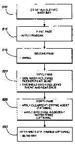
First, the vehicle is driven into the car wash bay as indicated by box 605.
During a
first pass 610, the gantry moves along and over the vehicle at a first speed
(1 foot per second
in one preferred embodiment), typically from the front of the vehicle to the
back, spraying
the vehicle with a presoak solution from the presoak nozzles 242. Also during
the first pass,
the length of the vehicle is determined and relative height of the vehicle is
profiled for
reasons that will become apparent below.
During a second pass 615, the gantry travels back beyond the front of the
vehicle at a
second speed. During the time it takes for the gantry to travel from the back
to front, the
presoak solution has time to penetrate and loosen any dirt on the vehicle's
surface. It can be
appreciated that the second speed of the gantry 205 can be set via the
microprocessor
controller at different rates depending on various factors including, but not
limited to, the
time of year (longer soaks may be used in the winter when more dirt and salt
is likely to be
on the vehicle), and the premium level of the wash (economy washes may have
shorter
soaks than "the works" washes).
28
CA 02565952 2006-11-15
During the third pass 620 water under high pressure is sprayed from the both
the side
and top high pressure nozzles 230 and 256. As described above, the side
nozzles 230 can
comprise a lower set of rocker panel nozzles 230A, a set of middle turbo
nozzles 230B and a
set of upper turbo nozzles 230C. As the gantry passes over the hood of a
typical vehicle,
both the middle set of nozzles 230B and the rocker panel Masters 230A are
activated, and
depending on the height of the hood and trunk, the upper set of nozzles 230C
may not be
activated. If the vehicle has a low hood/trunk height, the solenoid valve
connected to the
upper set of nozzles will close to prevent cleaning solution from needlessly
being sprayed
over the top of the hood and trunk. On the other hand, if the hood and/or
trunk has a high
profile then the upper nozzles 230C will be activated as the clearance eye
sensor 232 located
on one of the gantry legs senses the increased height of the vehicle. As the
gantry passes
over the middle portion of the vehicle, the rocker panel, middle and upper
nozzles are all
typically activated. Next, as the gantry passes over the back of the vehicle
the upper set of
nozzles 230C may be deactivated if the vehicle has a low trunk as typically
would be the
1 S case with a sedan.
Before the Gantry passes over the vehicle during the third pass, the moveable
platform 240 is lowered until it is in front of the front of the vehicle and
the pivoting boom
245 is rotated until the upper nozzles 256 face the front of the vehicle. The
nozzles 256 are
activated and the front of the vehicle is impacted by jets of fluid as the
platform 240 is
raised. Once the platform 240 has been raised above the height of the front
end, the pivoting
boom 245 is rotated back to its unpivoted centered position with the nozzles
256 facing
downwardly. Next, the gantry during the third pass passes over the hood of the
vehicle with
the nozzles 256 spraying jets of water downwardly. Depending on the height of
the hood the
movable platform 240 may be held in a position below the retracted position
such that the
distance between the hood and the nozzles 256 is reduced. As the gantry passes
over the
windshield, the moveable platform 240 rises to clear the roof and/or maintain
a preferred
distance between the nozzles 256 and the top surface of the vehicle. Depending
on the
height of the rear portion of the vehicle, the platform 240 may again be
lowered to maintain
a preferred distance between the surface of the rear deck and the nozzles 256.
Finally, the
gantry moves behind the vehicle and the moveable platform 240 is lowered until
it is located
29
CA 02565952 2006-11-15
behind the back of the vehicle. Simultaneously, the pivoting boom 245 is
rotated so that the
nozzles 256 face the front of the vehicle. Once the backside of the vehicle
has been washed,
the boom 245 rotates back to its neutral position and the moveable platform
240 ascends to
its retracted position.
The speed at which the gantry 205 passes over the vehicle 120 during the third
pass
(0.57 feet/second in one preferred embodiment) is typically slower than the
speed of the first
pass. Further, different gantry speeds may be specified for a plurality of
zones of the vehicle.
The zones are determined as the vehicle is profiled during the first pass and
typically include
(i) the length of the vehicle that corresponds to the hood, (ii) the length of
the vehicle that
corresponds to the cab, and (iii) the length of the vehicle that corresponds
to the trunk. It is
appreciated that high profile vehicles, such as SUV's and vans may not include
all of the
three typical zones depending on their configurations. Varying the speed of
the gantry based
on the various zones of a vehicle is discussed in greater detail below in the
section entitled
"Speed Profiling."
During the forth pass 625 at a fourth speed (1.5 feet/second in one preferred
embodiment), the gantry is moved from the back of the vehicle towards its
initial position in
front of the vehicle. Both a clear coat and a spot free rinse are applied in
the manner
described previously. Fifth and/or sixth optional passes at a fifth speed
(0.33 feet/second in
one preferred embodiment) may be included wherein a dryer apparatus 220
mounted on the
gantry dries the vehicle. Alternatively, stationary blowers may dry the
vehicle as it passes
out of the wash bay. It is also appreciated that a three cycle wash may also
be run in which
the forth pass is not utilized.
It is appreciated that any number of sensor arrays maybe utilized to determine
the
profile of the vehicle being washed. The preferred embodiment, however,
utilizes a
clearance eye sensor 232 and front and rear locator sensors 233 and 234, as
illustrated in
Figure 2. The clearance sensor eye 232 is located on one of the legs of the
gantry in a
vertical position below the lowest overhead deployed position of the moveable
platform 240.
Typically, the clearance sensor 232 will be positioned approximately 40 to 46
inches off the
floor of the vehicle wash bay. If the "beam" of the sensor 232 is broken, it
indicates a
portion of a vehicle with a height above the height of the clearance sensor,
and the upper set
CA 02565952 2006-11-15
of side nozzles 230C are typically activated by the control system. If the
beam is intact, a
lower portion of the vehicle is indicated, causing the control system to lower
the moveable
platform 240 and to deactivate the upper set of side nozzles 230C.
The front and rear sensors 233 and 234 indicate whether the gantry is in front
of or
behind the vehicle. Typically, these sensors are located closer to the floor
on one of the
gantry legs, the front sensor 233 proximate the front face of the gantry, and
the rear sensor
234 proximate the rear face of the gantry. An unobstructed sensor "beam"
indicates that the
gantry is either in front of or behind the vehicle. Typically, when both beams
become
unobstructed the control system recognizes the gantry is either in front of or
behind the
vehicle and it then travels an additional predetermined distance in its
direction of travel to
ensure it is behind or in front of the vehicle enough to allow operation of
the moveable
platform 240 and pivot boom 245 to clean the respective front or rear end of
the vehicle.
Pressure Profiling
By selectively turning the various sets of nozzles of the vehicle wash system
off and
on depending on the position of the gantry 205 relative to the vehicle 120,
the pressure of
the cleaning solution exiting the active nozzles can be varied to maximize the
vehicle wash
system's cleaning effectiveness. During the wash cycle, while the moveable
platform 240 is
lowered so that the boom nozzles 256 face the front surfaces of a vehicle, the
gantry side
nozzles 230 are deactivated so that the pressurized cleaning solution is sent
only to the boom
nozzles 256 at the highest possible pressure. In one embodiment, the pressure
of the
cleaning solution supplied to the boom nozzles ranges from 1100 to 1300 pounds
per square
inch (psi) with 1100 psi being typical. The high pressure helps facilitate the
effective
cleaning of the typically hard to clean front end of a vehicle. It is
appreciated the side
nozzles 230 may also be deactivated when the platform is lowered to clean the
rear end of a
vehicle.
As the boom is retracted and the gantry moves over the hood, the lower side
nozzles
230A and B are activated which causes the pressure to drop to a second
intermediate level
(900-1100 psi in one embodiment with 1000 psi being typical). Cleaning
solution exiting the
active nozzles at this intermediate pressure is effective in cleaning the
front fender surfaces
that are often dirtier than other parts of a vehicle due to the fenders
proximity to the wheels
31
CA 02565952 2006-11-15
and splash back often caused by driving through puddles. Further, the distance
between the
bottom of the boom nozzles 256 and the surface of the hood (or trunk) is often
greater than
the distance between the boom nozzles and the top surface of the cab,
accordingly, the
higher pressure cleaning solution is desirable when the boom nozzles are over
the hood and
trunk.
Finally, over the center portion of the vehicle, typically corresponding to
the
vehicle's cab, the upper side nozzles 230C are activated and are utilized in
conjunction with
the lower side nozzles 230A and B and the boom nozzles 256. As a result, the
pressure of
the cleaning fluid exiting the nozzles drops to a third level that is lower
than the first and
second levels (less than 900 psi in one embodiment with 800 psi being
typical). Since the
top surface of a vehicle and the side surfaces proximate the cab do not
typically get as dirty
as the front surfaces and the fender surfaces, the lower pressure cleaning
solution is effective
in cleaning the vehicle in these areas.
Speed Profiling
Speed profiling is a process by which the controller of the vehicle wash
system
adjusts the speed at which the fluid nozzles are moved along the vehicle
relative to the
vehicle depending on the profile of the vehicle. As described above, the
nozzles are typically
attached to a moveable gantry in the preferred embodiments, although the
nozzles may be
attached to any suitable type of framework in alternative types of vehicle
washes. In a
manner similar to that described above, one or more sensors are utilized to
determine the
profile of the vehicle. An exemplary method of speed profiling is described
herein for a
gantry-type wash system during the wash passes) (described above as the third
pass). It is to
be appreciated that the speed at which the various nozzles move relative to
the vehicle
during a pass may be varied in other passes as well, such as the presoak pass,
the clear coat
application or spot free rinse passes. Further, the speed at which a drying
blower passes over
a vehicle may also be varied depending on the profile of the vehicle that is
being dried.
As illustrated in Figure 45, the profile of the vehicle is divided is
typically divided
into three zones: a hood zone 4505; a cab zone 4510; and a trunk zone 4515.
The hood zone
4505 comprises the front portion of a vehicle that is typically less than 42"
above the floor
of the vehicle wash's bay. The cab zone 4510 comprises the portion of the
vehicle that has a
32
CA 02565952 2006-11-15
height in excess of 42" and the trunk zone 4515 comprises the rear portion of
the vehicle
that has a height of less than 42". It is appreciated that certain vehicles
depending on their
profile may only have one or two zones or more than three zones. For example,
the height of
a van may be in excess of 42" along substantially its entire length so it
would only have a
cab zone. An SUV would generally have a hood zone and a cab zone, but no trunk
zone. It is
further appreciated that a different zone dividing height other than 42" may
be utilized in
alternative embodiments.
Through the controller, the speed of the gantry 205 relative to a vehicle 120
can be
set independently to anyone of 10-15 available speeds (other numbers of
available speeds
may be specified in other embodiments). For example, the speed in the hood
zone 4505 can
be set relatively low to ensure that the hard to clean front of the vehicle
and the fenders are
blasted with a greater amount of cleaning solution. Conversely, the speed of
the gantry 205
as it travels over the cab zone 4510 can be set at a higher speed since the
cab zone of a
vehicle is typically not as dirty as the hood zone. Additionally, the speed of
the gantry may
be set to an intermediate speed as it travels over the trunk zone of a
vehicle. The operator
may also program the controller to move the gantry at different speeds
depending on the
type of vehicle that is being washed or based on the premium level of the
wash. For
example, if a premium wash is chosen, the gantry may move at relatively slow
speeds during
the wash cycle when compared to the speeds utilized in an economy wash. It is
to be
appreciated that there are a large of number potential combinations of speeds
that can be
programmed by a vehicle wash operator to accommodate the operators desires
regarding the
quality and effectiveness of a wash compared with the cost and time necessary
to perform an
entire wash.
Because the moveable platform 240 lowers itself to a position in front of the
vehicle,
the vehicle wash system controller is adapted to monitor and control the
movement of the
platform 240 and/or the gantry 205 to ensure that the moveable platform does
not come into
contact with the vehicle during a wash operation. Figure 46 is a block diagram
illustrating
how a computerized controller can be interfaced to ensure proper operation of
the vehicle
wash system. The controller 4610 is typically comprised of a microprocessor
and associated
computer readable memory for storing operator instructions and profile
information for a
33
CA 02565952 2006-11-15
vehicle being washed. The controller is coupled with a user interface 4620
through which an
operator may program the various wash options including the gantry speeds to
be utilized
during the various passes of the gantry 205 during a wash. A second user
interface (not
shown) may also be provided through which the owner of a vehicle may deposit
money and
select a wash for his vehicle.
The controller 4610 is also coupled to a number of sensors including profiling
sensors 4630, a moveable platform position sensor 4640 and a pulsar wheel
sensor 4650.
The profiling sensors 4630 determine the locations and positions of the
various zones of the
vehicle. The moveable platform position sensor 4640 determines the vertical
position of the
platform 240. In one embodiment, the platform position sensor 4640 measures
the number
of rotations of a pulley wheel over which the drive belt 285 passes to
determine the position
of the platform below its stowed location. The pulsar wheel sensor 4650
measures the
number of rotations of the pulsar wheel. The pulsar wheel is coupled with a
idler wheel that
is in direct contact with one of the guide rails. The controller 4610 utilizes
the signals from
the pulsar wheel sensor to calculate the position of the gantry 205 relative
to a reference
position. It is appreciated that a wide variety of sensors and sensor types
may be utilized to
determine the positions of the gantry 205 and the moveable platform 240 as
would be
obvious to one of ordinary skill in the art. Finally, the controller 4610 is
coupled with (i) the
gear motor 4660 for moving the gantry 205 and (ii) the pneumatic lift 270 for
vertically
moving the platform 240.
Refernng back to Figure 45, the operation of the gantry 205 utilizing speed
profiling
will be described. First, the vehicle is profiled during the presoak or first
pass from the front
of the vehicle to the rear. The gantry then returns to a position in front of
the vehicle after
the soak (or second) pass. Next, the moveable platform 240 lowers itself and
the boom 245
tilts inwardly so that the boom nozzles 256 face the front of the vehicle. In
a preferred
embodiment, the platform 240 is lowered 41" below its stowed position and is
located 24" in
front of the front end of the vehicle in a front high pressure position (FHPP)
4520. The
nozzles 256 are activated and cleaning solution is sprayed onto the vehicle.
The gantry 205 begins to move rearwardly at the predetermined speed for the
hood
zone 4505 that has been set by the operator. As the gantry moves, the moveable
platform
34
CA 02565952 2006-11-15
240 shown by the dotted line 4525 in Figure 45, is raised vertically at a rate
equal to the
horizontal rate of movement of the gantry 205 providing the length of the hood
zone 4505 is
sufficient. Additionally, as the platform is raised, the boom 245 rotates back
to its nominal
position with the nozzles 256 pointed downwardly. In the preferred embodiment
when
cleaning a vehicle with a relatively long hood zone, the platform 240 is
raised 31" to a front
profiling start position (PSPF) 4530, wherein the platform 240 is deployed 11"
below its
stowed position.
From the PSPF 4530, the gantry 205 continues to move rearwardly at the
predetermined speed with the platform 240 disposed a distance below the stowed
position
until the gantry 205 and the associated platform 240 reach front profiling end
position
(PEPF) 4535 which in the preferred embodiment is 6" from the rear end of the
hood zone
4505. From the PEPF 4535 to rear end of the hood zone, the platform 240 is
raised into its
stowed position prior to entering the cab zone 4510, at location 4540.
During the ascent of the platform 240 and the rearward travel of the gantry
205 over
the hood zone 4505, the relative positions of the gantry and the platform are
continuously
monitored by the controller 4610 through the appropriate sensors to ensure the
platform is
ascending at the proper rate. In certain circumstances it is possible that the
platform 240
cannot ascend as fast as the gantry 205 is being moved rearwardly. For
instance, the
operational speed of the pneumatic lift 270 can vary with temperature. The
pneumatic lift
270 may not be able to move the platform as 240 quickly when it is first used
in the morning
as when it has "warmed up." It can be appreciated that the platform could
impact the hood
of the vehicle if the platform 240 is not raised fast enough, especially if
one of the higher
speeds is specified for the gantry's rate of travel in the hood zone 4505.
Accordingly, the
controller 4610 will stop the gear motor 4660 if the ascension rate of the
platform 240 falls
below the travel rate of the gantry. The controller will not restart the gear
motor 4660 until
the platform 240 has caught up. Should the platform fall behind again, the
controller will
again stop the gear motor. In this manner, the platform will not be permitted
to physically
impact the hood of the vehicle. In a similar manner, the controller turns the
gear motor off
and on as the platform ascends between the PEPF 4535 and the rear end of the
hood zone
4505.
CA 02565952 2006-11-15
With certain vehicles, the length of the hood zone 4505 is less than is
necessary to
permit the platform 240 to rise at a one to one relationship with the movement
of the gantry
205. In such a situation, the controller 4610 sets the necessary rate of
vertical ascension of
the platform at a level that is greater than the speed of travel of the
gantry. As described
above, the controller will periodically stop the gear motor 4660 as necessary
to maintain the
proper ascension rate relative to gantry travel. On certain SUVs and vans that
do not have
hood zones, the platform 240 will usually descend in front of the vehicle in 3-
4" increments
to clean the front surfaces and then ascend back into the stowed position
before the gantry
begins moving rearwardly.
Next, the gantry travels rearwardly over the top of the vehicle's cab zone
4510 with
the platform 240 in its fully stowed position at a predetermined speed for the
cab zone that
may be different from the predetermined speed for the hood zone 4505. Once the
gantry 205
reaches the end of the cab zone at location 4545, the speed of the gantry's
rearward
movement changes to a predetermined speed selected for the trunk zone 4515 and
the
platform 240 begins to descend. Initially on a vehicle with a relatively long
trunk zone as
shown in Figure 45, the platform 240 in the preferred embodiment descends 11"
as it travels
6" rearwardly from the end of the cab zone 4545 to the rear profiling start
position (PSPR)
4550. From the PSPR 4550, the gantry of the preferred embodiment continues to
travel
rearwardly at the trunk zone predetermined speed with the platform 240
deployed 11" below
'the stowed position until the gantry reaches the rear Profiling End Position
(PEPR) 4555.
From the PEPR 4555, the platform 240 begins its descent to its fully deployed
position
behind the rear end of the vehicle into the rear high pressure position (RHPP)
4560. The
location of the PEPR 4555 is determined by the controller 2610 based on
several factors
including (i) the distance between the rear end of the vehicle and the RHPP
4560; (ii) the
length of the trunk zone 4515, and (iii) the preferred one to one descent rate
relative to the
speed of the gantry. For example, with a vehicle having a long trunk whose
rear end is 24"
from the RHPP 4560, the PEPR 4555 would begin 7" from the rear end of the
trunk zone
4515 thereby permitting the platform 240 to descend 31" as the gantry 205
travels 31 ". In
vehicles with short trunk zones 451 S, a greater rate of descent may be
specified.
36
CA 02565952 2006-11-15
With vans, SUVs and other vehicles that do not have a trunk zone, the platform
240
will remain in its stowed position until the gantry 205 is located behind the
vehicle and the
platform can safely descend to the RHPP 4560. In a preferred embodiment, the
platform
descends slowly to the RHPP 4560 from the stowed position in discrete steps
(typically 3
4"). As the boom is lowered, cleaning solution is sprayed onto the rear
surface of the vehicle
using the boom nozzles. In embodiments incorporating pressure profiling,
cleaning solution
can be sent to the boom nozzles alone at a high pressure level as the platform
descends to
maximize cleaning effectiveness. It is to be appreciate that a similar process
can also be used
to clean the front surface of vehicles that do not have a hood zone.
As described above concerning the hood zone 4505, the pneumatic lift 270 may
not
be capable of lowering the platform 240 fast enough to maintain the controller-
specified
descent rate based on the trunk zone predetermined speed of the gantry. Unlike
with the
ascent of the platform over the hood zone, there is no threat that the
platform will impact the
vehicle if it descends too slowly. Accordingly, the controller 2610 permits
the gantry 205 to
continue on its rearward travel unimpeded at the predetermined speed
regardless of the
location of the platform.
The various distances and dimensions specified herein relate to a preferred
embodiment of the vehicle wash system and a wide variety of variations are
anticipated that
could be effectively utilized with speed profiling. Further, similar speed
profiling operations
may also be utilized in other passes during a vehicle wash, or when the gantry
is moving
from the rear of the vehicle to the front of the vehicle. In general, when the
gantry is moving
towards the cab zone 4510 (i.e. the zone where the vehicles height is greater
than a specified
height) the gear motor 4660, which is moving the gantry 205 at a pre-selected
speed, will be
deactivated by the controller if the platform 240 does not ascend at a
controller determined
rate to permit the platform to catch up. Conversely, when the gantry is moving
away from
the cab zone, the gantry will be permitted to move at the preselected speed
regardless of the
position of the platform.
The Dump Valve
After a wash cycle as described above, it is desirable to purge the cleaning
solution
from the boom nozzles 256, as well as, the hoses (and/or supply lines) that
fluidly connect
37
CA 02565952 2006-11-15
the nozzles to the source of the cleaning solution. If the nozzles and supply
lines are not
purged, cleaning solution (typically, soft water) left in the nozzles and
supply lines may drip
onto the vehicles surface during a spot free vehicle rinse and/or clear coat
application. Drops
of soft water, as opposed to the reverse osmosis water that is typically used
in a spot free
S rinse solution, may leave unsightly white rings on the vehicle after drying.
In prior art vehicle wash systems, the cleaning solution is purged from the
nozzles
and supply hoses using pressurized air prior to beginning a rinse or clear
coat application
pass. However, the time necessary to blow out the nozzles can be prohibitive,
especially if
the nozzles have large bodies, such as slow rotating turbo and oscillating
nozzles.
Accordingly, a dump valve is attached inline with a supply hose to the boom
nozzles at a
location near the base of the gantry. When the gantry has completed its wash
pass, the dump
valve is opened by the controller and the majority of the cleaning solution in
the supply
hoses and boom nozzles is siphoned onto the floor of the vehicle wash bay.
Subsequently a
relatively short blast of pressurized air through the supply hoses and the
nozzles can
1 S effectively purge any remaining cleaning solution.
Turbo and Oscillating Nozzles
As described above various types of high pressure nozzles are utilized in the
various
embodiments of the present invention, including zero degree nozzles, fast
rotating turbo
nozzles, slow rotating turbo nozzles, and oscillating nozzles. Zero degree
nozzles are well
known in the art and are commercially available from a variety of vendors.
Typically, zero
degree nozzles shoot a single jet of fluid from a fixed orifice, such that
each they impact on
a relatively small area on the surface of a vehicle when used in conjunction
with a vehicle
wash system. Accordingly, they are typically utilized with rotating wands that
move the
nozzles over the surface of the vehicle to obtain complete coverage of the
associated surface,
such as the rotating wand assemblies described concerning the first
embodiment. Given the
high integrity of the fluid jets that emanate from Zero degree nozzles, they
typically have a
maximum effective range of up to 80 inches.
As illustrated in Figure 34, both the fast and slow rotating turbo nozzles
comprise a
rotating nozzle member 805 that has an orifice 810 that rotates within the
body 815 of the
nozzle causing the fluid jet emanating therefrom to assume a spiral shape as
illustrated in
38
CA 02565952 2006-11-15
Figure 16. This causes a single turbo nozzle to have a circular impact area,
which makes
obtaining complete coverage of the vehicle surfaces simpler. For instance, in
certain
circumstances, the use of fast rotating turbo nozzles 405 with the
reciprocating wand
assemblies 400 of the second alternative embodiment result in better coverage
of the vehicle
surfaces and more effective cleaning of the surfaces than the zero degree
nozzles used with
the rotating wands of the first embodiment. Furthermore, by substituting fast
rotating turbo
nozzles for the zero degree nozzles in the rotating wands of the first
embodiment, multiple
impacts of the stream with the automobile surfaces results for improved
cleaning
performance. The versatility of the fast rotating turbo nozzle is also
demonstrated by the
second alternative embodiment where the use of reciprocating wands are
eliminated, since
turbo nozzles with spray patterns that overlap at least partially can
effectively clean the
entire top surface of a vehicle when combined with the movement of the gantry
over the
vehicle. It is also noted that the series of turbo nozzles located on either
leg of the gantry
effectively replace side wand assemblies utilizing zero degree nozzles without
a reduction in
cleaning effectiveness. Another advantage of turbo nozzles generally is there
ability to
operate effectively at lower pressures than the typical zero degree nozzle.
Whereas, zero
degree nozzles generally require pressures of around 900 psi or greater,
typical turbo nozzles
can operate at pressures of as low as 600 psi.
Fast rotating turbo nozzles, in which the nozzle orifice rotates at speeds of
round
1600 to 2000 rpm, are commercially available in a variety of sizes from
several vendors and
have been utilized in various applications on vehicle wash systems. However,
fast rotating
turbo nozzles suffer from a drawback that has limited their application in
certain vehicle
wash system applications, namely, they have a limited effective range of 28"
to 36"
depending on the size of the fast rotating nozzle specified. At distances in
excess of the
effective range, the spiraling fluid jet looses its integrity and becomes a
mist, which
although increasing the coverage of the underlying surface, does not impart
enough of an
impact force on the vehicle to effectively dislodge dirt and debris. It can be
appreciated that
the total distance traveled by any portion of cleaning solution in a spiraling
fluid jet as it
spirals towards a vehicle's surface is much greater than the distance between
the nozzle
orifice and the surface to be cleaned. In other words, the length of an
uncoiled spiraling jet
39
CA 02565952 2006-11-15
would be much greater than the distance between the nozzle tip and the surface
of the
vehicle. It follows, therefore, that the aerodynamic drag incident on a
spiraling fluid jet
from mist and air would be significantly greater than on a comparable straight
fluid jet (such
as from a zero degree nozzle). This aerodynamic drag tends to dissipate some
of the
spiraling j ets energy. Furthermore, the complex force vectors acting on the
spiraling fluid j et
as it leaves the nozzle and travel towards the vehicle surfaces tends to
compromise the
integrity of the spiraling jet contributing to its effective disintegration at
much short
distances than a comparable straight fluid jet.
Slow rotating turbo nozzles of the present invention as their name would
suggest
rotate at greatly reduced rate of around 600-1400 rpm when compared to their
fast rotating
cousins. The fluid j ets emanating from them spiral at a significantly slower
rate than their
fast rotating cousins, making less turns before reaching the surface of the
vehicle. The
distance traveled by any portion of the fluid jet from a slow rotating turbo
nozzle would be
less than that of a jet from a fast rotating nozzle situated a similar
distance from a vehicle
surface. The fluid jet of a slow rotating turbo nozzle would, therefore,
encounter less energy
dissipating aerodynamic drag than its fast rotating cousin and the energy of
the fluid jet from
the slow rotating turbo nozzle would dissipate less than the fluid jet from
the fast rotating
turbo nozzle. Accordingly, a slow rotating turbo nozzle has a greater
effective range
(similarly sized fast and slow rotating turbo nozzles have approximate ranges
of 36" and 42"
respectively). Even at distances within the effective ranges of the fast
rotating turbo nozzle,
the slow rotating turbo nozzles delivers a fluid jet having a greater impact
force per unit area
than the comparable fast rotating turbo nozzle. By using slow rotating turbo
nozzles in a
vehicle wash system, all surfaces of the vehicle can be hit with jets of
cleaning solution at
effective levels of impact force to dislodge most dirt and debris, especially
those on
contoured surfaces of a vehicle that might be outside of the range of fast
rotating turbo
nozzles.
Figures 34-40 and Figure 42 illustrate a slow rotating turbo nozzle.
Furthermore,
Figure 41 illustrates a cross section of a fast rotating turbo nozzle for
purposes of
comparison. Unless otherwise indicated, the description proved herein
generally applies to
CA 02565952 2006-11-15
both fast and slow rotating turbo nozzles. Distinctions between the fast and
slow turbo
nozzles will be specifically indicated.
As shown in Figure 34, A typical turbo nozzle comprises three basic
components: a
nozzle body 815; an inlet cap 820 that is threadably received into the top of
the body; and a
rotating nozzle member 805 that is contained within the body. The hollow
nozzle body 815
has a generally conical shape beginning with a threaded opening to receive the
inlet cap 820
at a distal end. From the distal end, the walls of the body 815 taper until
terminating at the
proximal end in a ceramic seat 825. The ceramic seat 825 has a concave inside
surface
configured to receive the orifice of the rotating nozzle member and a passage
830
therethrough to permit the fluid jet emanating from the orifice to exit the
turbo nozzle.
The inlet cap 820 is a generally cylindrical member having a partially
threaded
outside surface for being received into the threaded opening of the nozzle
body 81 S with an
o-ring seal 835 disposed thereon. The inlet cap 820 further comprises a
vertical bore 840
that is partially threaded for coupling with a cleaning solution supply
manifold or hose. The
1 S bore is closed at its bottom end; however, one or more small jet
passageways 845 extend
through the vertical wall of the bore 840 at generally acute angles and into
the interior of the
nozzle body 815 as illustrated in Figure 37. The angles that the one or more
passageways
845 extend through the wall, the diameter of the passageways and the
interaction between
the fluid jets emanating thereform during operation are all critical in
determining the
rotational speed of the turbo nozzle as will be described below. Lastly, A
small nib 850
extends from the center of the outside surface of the closed bottom end of the
inlet cap 820
for reasons that will become apparent.
The rotating nozzle member 805 is illustrated in isolation in Figures 35 and
36. The
rotating nozzle member 805 typically comprises a brass tube 855 having a
perforated
support piece 860 spanning the interior of the tube proximate its distal end
to provide
support and additional strength thereto. The distal end of the tube is capped
with a ceramic
orifice 810 from which the spiraling jet of the turbo nozzle emanates. The
ceramic orifice
810 has a generally conical shape that terminates in a rounded end. The
rounded end is sized
to nest in the concave portion of the ceramic seat 825 such that when under
pressure the
41
CA 02565952 2006-11-15
ceramic orifice 810 effectively seals the passage through the ceramic seat
825. The diameter
of the ceramic orifice 810 ultimately controls the volumetric output of the
nozzle.
The outside surface of the brass tube 855 is covered by one or more plastic
shrouds
865, 870 and 875. In general, the plastic shrouds serve to protect the brass
tube 855 as the
S nozzle member 805 is rotated within the nozzle body 815 at high speeds.
Depending on the
particular configuration of the turbo nozzle, a single unitary plastic shroud
maybe utilized,
although as illustrated, three separate and distinct shrouds 865, 870 and 875
are indicated.
The upper shroud 865 serves to guide the nozzle member 805 around the nib 850,
as best
illustrated in Figures 34 and 38. The middle shroud 870, which is shown having
a
hexagonal outer surface, serves to guide the nozzle member 805 along the
inside surface of
the nozzle body 815 as best illustrated in Figure 39. Because the middle
shroud 370 is
hexagonal, it will cause the orifice 810 to rotate in a more hexagonal
pattern, thereby
altering the characteristics of the fluid jet emanating therefrom.
Furthermore, the hexagonal
surface of the middle shroud 870 will not rotate as easily around the inside
surface of the
nozzle body 815, thereby increasing the rotational friction of the nozzle
member 805,
slowing its effective rate of rotation even further. As illustrated in Figure
40, the hexagonal
shroud 370 can be replaced with a circular shroud 870A in variations thereof.
The operation of a typical turbo jet will now be described. First, the
cleaning solution
enters the inlet cap 820 from a source under high pressure. The cleaning
solution then
travels through the one or more passageways 845, wherein the cleaning solution
is
accelerated and is propelled from the nozzles as a stream in a direction
generally
perpendicular with the center axis of the turbo nozzle towards the
corresponding inner
surface of the body 815. The stream impacts inner surface of the body 815 at
an acute angle,
which induces the cleaning solution to rotate in a clockwise direction. A
clockwise vortex of
cleaning fluid is created within the body 815 which is completely filled with
the pressurized
cleaning solution during operation. By reversing the angle of incidence
between the stream
and the wall of the body, a counterclockwise vortex could be created as well.
The vortex
causes the nozzle member 805, which is in its path, to rotate at essentially
the same velocity
as the vortex. It is appreciated that the nib 850 prevents the nozzle member
805 from
positioning itself in the calm center of the vortex. Next, the pressurized
cleaning fluid
42
CA 02565952 2006-11-15
contained in the body is forced into the top end of nozzle tube 855 and
through the orifice
810, wherein the cleaning solution is accelerated and exits the nozzle in the
form of a
spiraling fluid j et.
The speed of rotation of the nozzle and the speed of rotation of the fluid jet
emanating therefrom is directly related to the rotational velocity of the
vortex created within
the nozzle body 815. The velocity of the vortex is dependent on both the angle
at which the
fluid streams emanating from the inlet cap passageways 845 are incident on the
inner
surface of the body wall, as well as, the velocity of the streams. A
horizontal cross section of
a typical fast rotating turbo nozzle showing a single passageway 845 through
the bore 840 in
the inlet cap 820 into the body of the nozzle is illustrated in Figure 41. A
corresponding
section of a slow rotating turbo nozzle is illustrated in Figure 42, wherein
four passageways
845 are shown. The four passageways 845 have a combined cross sectional area
greater than
that of the single passageway 845 of fast rotating turbo nozzle of Figure 41.
For a given
pressure of fluid being passed through the passageways of both nozzles, the
fluid stream
emanating from the passageway of the fast rotating nozzle will be faster than
the streams
emanating from each of the passageways of the slow rotating turbo nozzle.
Accordingly, the
rotational speed of the vortex created in the slow rotator will be less than
the speed of the
vortex in the fast rotator, resulting in a slower rotating nozzle member.
Other means of creating a slow rotating turbo nozzle are also contemplated.
For
instance, a set of one or more passageways 845 could pass through the inlet
cap 820 at one
angle while a second set of one or more passageways could pass through the
inlet cap at a
second angle, such that the streams emanating from the second set interfere
with the vortex
caused by the streams from the first set such that the speed of the vortex is
reduced. For
instance, streams from the first set of passageways 845 may induce a clockwise
rotating
vortex in the nozzle body 815 having a speed comparable to that of a vortex in
a fast rotating
turbo nozzle. The streams from the second set of passageways may exit the
passageways at
angles that would by themselves induce a counterclockwise rotation. The
combination of
these two sets of streams effectively results in a vortex of a reduced speed.
It is to be
appreciated that a wide variety of combinations of sets of passageways can be
utilized to
43
CA 02565952 2006-11-15
tailor the speed of the vortex and consequently the rotational speed of the
turbo nozzle to a
desired level.
Another type of nozzle used in embodiments of the present invention is an
oscillating
nozzle as shown in Figure 43. The fluid jet emanating from the oscillating
nozzle differs
from the fluid jet of turbo nozzle in that instead of spiraling, it moves back
and forth in a
generally linear path as illustrated in Figure 43. Oscillating nozzles with
small nozzle
bodies 915 are commercially available, which oscillate at a relatively fast
rate; whereas,
slower oscillating nozzles having large bodies 915 are not commercially
available, although
both designs operate in a similar manner as described herein. The oscillating
nozzle has an
inlet cap 920 and body 915 generally very similar to those on a turbo nozzle
except the
ceramic seat 925 is not fixed to the body 915, rather it is fixed to the lower
portion 970B of a
housing 970 contained within the body 915. The tube 955 to which the orifice
910 is affixed
is does not spin, nor does it rotate about a nib (not shown) on the inlet cap
920. Rather, it is
permitted only to pivot side within a slot 975 in the lower portion 970B of
the nozzle
1 S member housing 970. The lower portion 970B of the nozzle member housing
970 is fit into
an opening in the base of the body 915 such that it cannot spin but it can
pivot slightly. An
upper portion 970A of the housing portion is connected to the lower portion
970B, thereby
surrounding the nozzle tube. The attachment of the upper portion 970A with the
lower
portion 970B prevents it from spinning; however, it is free to rotate about
the nib on the inlet
cap 920 in a fluid vortex created in the body 915. Rotation of the upper
portion 970A of the
housing causes it to impact an o-ring 980 circumscribing the brass tube 955
proximate its
top end causing the orifice 910 to pivot back and forth in the slot 975.
In general, the effective range (approximately 45") of the oscillating nozzles
is
greater than that of the turbo nozzles; however, the range of faster small
body oscillators is
less than that of a slower large body oscillator. It is to be appreciated that
the speed of
oscillation is directly related to the velocity of the vortex created in the
nozzle body and the
distance that the vortex must travel to complete a revolution of the inside of
the body 915. It
follows that the speed of oscillation may be reduced by (1) increasing the
size of the nozzle
body whereby the vortex has a greater distance to travel to complete a
revolution, or the
Accordingly and/or (2) using the same types of modifications to the inlet cap
passageways
44
CA 02565952 2006-11-15
945 as described above for turbo nozzles to slow the velocity of the stream
emanating from
passageways 945.
Although the present invention has been described with a certain degree of
particularity, it is understood that the present disclosure has been made by
way of example,
and changes in detail or structure may be made without departing from the
spirit of the
invention as defined in the appended claims. For instance, the various
embodiments of the
vehicle wash system described above are typically of the gantry-type. It is to
be appreciated
that given the benefit of this disclosure that many of the features of the car
wash system may
be utilized in conjunction with other styles of vehicle washes. For instance,
features of this
invention can be adapted for use with a vehicle wash system having an inverted
L-shaped
wash wand with nozzles disposed thereon that travels around the perimeter of a
vehicle. In
this regard, unless otherwise indicated in the appended claims, the claims
shall apply to any
type of vehicle wash system. Further, the word "or" as used in one or more of
the appended
claims is to be construed inclusively to mean " one or another or both".
45