Sélection de la langue

Search

Sommaire du brevet 2567226 

Énoncé de désistement de responsabilité concernant l'information provenant de tiers

Une partie des informations de ce site Web a été fournie par des sources externes. Le gouvernement du Canada n'assume aucune responsabilité concernant la précision, l'actualité ou la fiabilité des informations fournies par les sources externes. Les utilisateurs qui désirent employer cette information devraient consulter directement la source des informations. Le contenu fourni par les sources externes n'est pas assujetti aux exigences sur les langues officielles, la protection des renseignements personnels et l'accessibilité.

Disponibilité de l'Abrégé et des Revendications

L'apparition de différences dans le texte et l'image des Revendications et de l'Abrégé dépend du moment auquel le document est publié. Les textes des Revendications et de l'Abrégé sont affichés :

  • lorsque la demande peut être examinée par le public;
  • lorsque le brevet est émis (délivrance).
(12) Demande de brevet: (11) CA 2567226
(54) Titre français: EMBALLAGE POUR COMPOSANTS ELECTRONIQUES, NOTAMMENT POUR BLOCS-NOTES ELECTRONIQUES
(54) Titre anglais: PACKING FOR ELECTRONIC COMPONENTS, IN PARTICULAR FOR NOTEBOOKS
Statut: Réputée abandonnée et au-delà du délai pour le rétablissement - en attente de la réponse à l’avis de communication rejetée
Données bibliographiques
(51) Classification internationale des brevets (CIB):
  • B65D 85/86 (2006.01)
  • B65D 81/05 (2006.01)
  • B65D 85/30 (2006.01)
(72) Inventeurs :
  • FRIEDRICH, HANNES (Allemagne)
(73) Titulaires :
  • MANFRED JACOB KUNSTSTOFFTECHNIK GMBH
(71) Demandeurs :
  • MANFRED JACOB KUNSTSTOFFTECHNIK GMBH (Allemagne)
(74) Agent: AVENTUM IP LAW LLP
(74) Co-agent:
(45) Délivré:
(22) Date de dépôt: 2006-11-07
(41) Mise à la disponibilité du public: 2008-05-07
Licence disponible: S.O.
Cédé au domaine public: S.O.
(25) Langue des documents déposés: Anglais

Traité de coopération en matière de brevets (PCT): Non

(30) Données de priorité de la demande: S.O.

Abrégés

Abrégé anglais


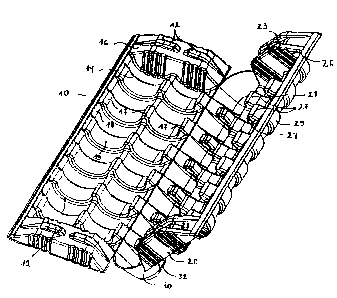
This invention relates to a packing for electronic components and devices and
preferably
for notebooks, characterized in that the packing includes at least two
pivotally connected
elements which can be swivelled between at least one first swivel position and
at least one
second swivel position, wherein in the second swivel position the elements
have a smaller
swivel angle with respect to each other than in the first swivel position, and
wherein in the
second swivel position the elements define a space for accommodating the
component to
be packed.

Revendications

Note : Les revendications sont présentées dans la langue officielle dans laquelle elles ont été soumises.


WE CLAIM:
1. A packing for electronic components and devices and preferably for
notebooks
(100), characterized in that the packing includes at least two pivotally
connected
elements (10, 20, 30, 40, 50) which can be swivelled between at least one
first swivel
position and at least one second swivel position, wherein in the second swivel
position the elements (10, 20, 30, 40, 50) have a smaller swivel angle with
respect to
each other than in the first swivel position, and wherein in the second swivel
position
the elements (10, 20, 30, 40, 50) define a space for accommodating the
component to
be packed.
2. The packing as claimed in claim 1, characterized in that one or more
elements (10,
20, 30, 40, 50) have locking means which fix the elements (10, 20, 30, 40, 50)
relative to each other in the second swivel position.
3. The packing as claimed in claim 2, characterized in that the locking means
comprise
a projection (12, 42) and a recess (23, 43, 53), the projection (12, 42) and
the recess
(22, 43) being arranged at the elements (10, 20, 30, 40, 50) such that in the
second
swivel position the projection (12, 42) is at least partly received in the
recess (23, 43,
53).
4. The packing as claimed in claim 3, characterized in that the locking means
is
configured such that a dovetail connection exists between the elements (10,
20, 30,
40, 50).
5. The packing as claimed in any of the preceding claims, characterized in
that the
elements (10, 20, 30, 40, 50) include a receiving portion (14, 24, 44, 54) and
one,
two or more than two edge portions (16, 26, 46, 56) which define the receiving
portion (14, 24, 44, 54) on one, on two or on more than two sides.

6. The packing as claimed in claim 5, characterized in that one or more
elements (10,
20, 30, 40, 50) have locking means which fix the elements (10, 20, 30, 40, 50)
relative to each other in the second swivel position, and that the locking
means are
disposed in the receiving portion (14, 24, 44, 54) and/or in the edge portion
(16, 26,
46, 56).
7. The packing as claimed in claim 5 or 6, characterized in that the edge
portions (16,
26, 46, 56) of the elements (10, 20, 30, 40, 50) are configured such that in
the second
swivel position they lie on top of each other and that the receiving portions
(14, 24,
44, 54) of the elements (10, 20, 30, 40, 50) are configured such that in the
second
swivel position they define a space for accommodating the component to be
packed.
8. The packing as claimed in any of the preceding claims, characterized in
that the
elements (10, 20, 30, 40, 50) have a receiving portion (14, 24, 44, 54) which
includes
bearing portions (17, 27, 47, 57) spaced from each other.
9. The packing as claimed in claim 8, characterized in that the bearing
portions (17, 27,
47, 57) are spaced from each other in the direction of the swivel axis of the
elements
(10, 20, 30, 40, 50) and/or in a direction vertical to the swivel axis of the
elements
(10, 20, 30, 40, 50).
10. The packing as claimed in claim 9, characterized in that webs (18, 28) or
grooves
(48, 58) extend between the bearing portions (17, 27, 47, 57) spaced in the
direction
of the swivel axis of the elements and arcuate portions (19, 29) extend
between the
bearing portions (17, 27, 47, 57) spaced from each other in a direction
vertical to the
swivel axis of the elements.
11. The packing as claimed in any of the preceding claims, characterized in
that the
packing consists of three elements (10, 20, 30), two of which (10, 20) are
arranged
11

substantially parallel in the second swivel position and with one swivel axis
each are
connected with the third element (30).
12. The packing as claimed in any of the preceding claims, characterized in
that the
elements (10, 20, 30, 40, 50) of the packing are arranged such that in their
second
swivel position they define a space which is open on one side only.
13. The packing as claimed in claim 11 or 12, characterized in that the third
element (30)
is configured such that in the second swivel position it has projections or
bulges (32)
pointing to the outside with respect to the space for accommodating the
component.
14. The packing as claimed in any of the preceding claims, characterized in
that the
packing includes a plurality of elements (10, 20, 30, 40, 50) which are
arranged such
that the first element (10, 50) and the last element (30, 40) of the packing
are
arranged parallel to each other in the second swivel position.
15. The packing as claimed in any of the preceding claims, characterized in
that one of
the elements (50) is formed by a plate-like component.
16. The packing as claimed in claim 15, characterized in that on one or more
sides,
preferably on two opposite sides, the plate-like component is pivotally
connected
with one or more further elements (40) of the packing.
17. The packing as claimed in claim 15 or 16, characterized in that the plate-
like
component includes a bearing surface (54) as well as one or more edge portions
(56)
which define the bearing surface (54) and protrude beyond the same.
18. The packing as claimed in claim 17, characterized in that in the bearing
surface (54)
protrusions (59) are provided, which are outwardly protruding with respect to
the
same.
12

19. The packing as claimed in claim 17 or 18, characterized in that the plate-
like
component has a rectangular or square configuration, that on two opposite
sides of
the component edge portions (56) are provided, which are raised with respect
to the
bearing surface (54), and that on the two remaining sides of the plate-like
component
one ore more further elements (40) are pivotally mounted.
20. The packing as claimed in any of the preceding claims, characterized in
that the
packing is made by deep-drawing.
21. The packing as claimed in any of the preceding claims, characterized in
that the
packing is made of a plastically deformable material or includes such
material.
22. Use of a packing as claimed in any of claims 1 to 21 for accommodating
electronic
components and devices and preferably notebooks (100).
23. The use as claimed in claim 22, characterized in that during assembly, the
electronic
component or device, preferably the notebook (100) rests on the plate-like
component formed by an element (50) and that subsequent to the assembly the
further elements (40) are swivelled relative to the plate-like component.
13

Description

Note : Les descriptions sont présentées dans la langue officielle dans laquelle elles ont été soumises.


CA 02567226 2006-11-07
10544P0203CA01
PACKING FOR ELECTRONIC COMPONENTS,
IN PARTICULAR FOR NOTEBOOKS
The present invention relates to a packing for electronic components and
devices and
pre:E'erably for notebooks.
Such packings are known in a number of different embodiments. Currently used
packings
are made for instance of expanded polystyrene or plastics. They are rigid
components,
which are for instance pushed onto a notebook from both sides.
As the packings known from the prior art constitute substantially rigid
components, the
sanie correspondingly are not flexible, but are each only usable for a
specific device. If
they are deep-drawn plastic packings, another disadvantage consists in that
the same must
have a considerable drawing depth, in order to ensure a sufficient insertion
depth of the
component, for instance the notebook, to be accommodated. Accordingly, the
process of
manufacturing such packings turns out to be relatively complex.
It is the object of the present invention to develop a packing for electronic
components and
devices, and preferably for notebooks, such that the same offers a good
protection of the
accommodated components or devices against being damaged and can be
manufactured
relatively easily.
This object is solved by a packing with the features of claim 1. Accordingly,
it is provided
that the packing includes at least two pivotally connected elements, which can
be swivelled
between at least one first swivel position and at least one second swivel
position, wherein
in the second swivel position the elements have a smaller swivel angle with
respect to each
other than in the first swivel position, and wherein in the second swivel
position the
elements defme a space for accommodating the component to be packed. Thus, the
packing of the present invention is not based on rigid packing elements, but
comprises
I

CA 02567226 2006-11-07
pivotally connected elements, which are movable into different positions and
in at least one
position form a space for the component or device to be accommodated. The
elements are
folded or rolled about the component/device to be packed, which can possibly
provide for
an adaptability to differently dimensioned components/devices.
Preferably, it is provided that one or more elements have locking means which
fix the
elements in the second swivel position relative to each other. The locking
elements can
comprise a projection and a recess, the projection and the recess being
arranged on the
elements such that in the second swivel position the projection is at least
partly received in
the recess. It is conceivable, for instance, that the locking means is
configured such that a
dovetail connection is formed between the elements.
In a preferred aspect of the invention it is provided that the elements
include a receiving
portion and one, two or more than two edge portions which define the receiving
portion on
one, two or more than two sides. The edge porkions thus form for instance a
lateral
boundary of the receiving portion and accordingly a lateral protection of the
accommodated component or device against being damaged.
Another function of the edge portions can consist in receiving said locking
means. In
principle, however, it is likewise conceivable to alternatively or
additionally arrange the
loclcing means in the receiving portion.
In another aspect of the invention it is provided that the edge portions of
the elements are
configured such that in the second swivel position they lie on top of each
other and that the
receiving portions of the elements are configured such that in the second
swivel position
they define a space for accommodating the component to be packed.
The elements can have a receiving portion which includes bearing portions
spaced from
each other. In this case, it is provided that the accommodated component or
device does
not lie flat on the receiving portion, but only or substantially on the
bearing portions.
2

CA 02567226 2006-11-07
The bearing portions can be spaced from each other in the direction of the
swivel axis of
the elements and/or in a direction vertical to the swivel axis of the
elements. Between the
bearing portions, webs, grooves or e.g. arcuate portions can be provided. For
instance,
between the bearing portions spaced in the direction of the swivel axis, webs
or grooves
can extend, and between the bearing portions spaced from each other in a
direction vertical
to the swivel axis of the elements, arcuate portions can extend, which
preferably are curved
to the outside, i.e. facing away from the receiving portion. A reverse
arrangement also is
conceivable. The arcuate portions provide on the one hand a certain
stabilization of the
receiving portion and on the other hand a protection against forces acting on
the receiving
portion from the outside.
In a further aspect of the invention it is provided that the packing consists
of three
elements, two of which are arranged substantially parallel in the second
swivel position
and, with one swivel axis each are connected with the third element.
In a preferred aspect of the invention it is provided that the elements of the
packing are
arranged such that in their second swivel position they define a space which
is open on one
side only. In this space, the accommodated component or device is located,
which in
accordance with this embodiment is surrounded by the packing of the invention
on its
upper and lower surfaces, on its two lateral surfaces and on its end face.
The third element can be configured such that in the second swivel position it
includes
projections or bulges pointing to the outside with respect to the space for
accommodating
the component. These projections or bulges on the one hand serve to stabilize
the third
element and on the other hand provide protection of the component or element
against
being damaged, as they are preferably deformed plastically like the further
components of
the paclting, in case an external force is acting on the same.
The packing can include a plurality of elements which are arranged such that
in the second
3

CA 02567226 2006-11-07
swivel position the first element and the last element of the packing are
arranged parallel to
each other. Preferably, these two elements define a surface from which
protrudes the
component or device accommodated in the packing.
Particularly advantageously, one of the elements is formed by a plate-like
component. On
one or more sides, preferably on two opposite sides, the plate-like component
can be
pivotally connected with one or more further elements of the packing.
Preferably, it is provided that the plate-like component includes a bearing
surface as well
as one or more edge portions raised from the same, which define the bearing
surface. For
protection of the accommodated component or device it can be provided that the
bearing
surface includes projections protruding from the same to the outside.
The plate-like component can, for instance, have a rectangular or square
configuration,
raised edge portions being provided on two opposite sides of the component and
one or
moi-e further elements being each pivotally mounted on the two other sides of
the
component.
Particularly advantageously, the packing is made of plastics. The packing can
be made by
deep-drawing. Due to the inventive configuration of the packing as compared to
known
packings, which for instance are pushed onto a notebook, a comparatively small
drawing
depth is required, which simplifies the manufacture accordingly.
Preferably, the packing is made of a plastically deformable material or
includes such
material. The material preferably is made such that in the case of an impact
or under the
influence of external forces it is deformed plastically and correspondingly
protects the
cornponent by absorbing the impact energy.
The present invention furthermore relates to the use of a packing as claimed
in any of
claims 1 to 21 for accommodating electronic components or devices and
preferably a
notebook.
4

CA 02567226 2006-11-07
Particularly advantageously, the packing is used such that the electronic
component or
deviice or the notebook rests on the plate-like component of the packing,
while assembly of
the component or device is effected or the same is equipped. Upon termination
of the
assembly, the further elements pivotally mounted relative to the plate-like
component are
folded down or rolled up, so that the finished component or device possibly
can be
delivered or stored after further packiing operations.
Further details and advantages of the invention will be explained in detail
with reference to
an embodiment illustrated in the drawing, in which:
Fig. 1: shows a perspective representation of the packing of the invention in
a first
embodiment in a first swivel position,
Fig. 2: shows a perspective representation of two packings as shown in Fig. 1
in a
second swivel position with a notebook accommodated therein,
Fig. 3: shows a perspective representation of the packing as shown in Fig. 1
in a
second swivel position,
Fig. 4: shows a perspective representation of the packing of the invention in
a
further embodiment in a second swivel position,
Figõ 5: shows a perspective representation of the packing as shown in Fig. 4
in the
first swivel position, and
Fig. 6: shows a perspective representation of the packing as shown in Fig. 4
in a
second swivel position with a notebook accommodated therein.
Fig. 1 shows the packing of the invention in a first embodiiment. It consists
of the three
parts 10, 20, 30 pivotally mounted with respect to each other, which are
integrally made by
deep-drawing. At their edges extending in longitudinal direction of the
elements, the
elements 10 and 30 as well as 30 and 20 are connected with each other such
that they can
be swivelled against each other.
Fig. 1 shows the packing in a first swivel position and Fig. 3 in a second
swivel position,

CA 02567226 2006-11-07
Fig. 3 illustrating that in the second swivel position the angle included
between the
elements is smaller than in the first swivel position.
In the fu-st swivel position shown in Fig. 1, the paclcing is open and in this
position easily
provides for insertion of a component or device. As soon as the same is
located in the
corresponding bearing portions, the element 20 is folded against the element
10, so that
there is formed a space defined by the packing on five sides, which only
includes one
opening extending between the edges of the elements 10 and 20, on which no
further
elernents are disposed.
To ensure that upon folding the elements 10, 20 remain in their folded
position as shown in
Figõ 3, locking means are provided in the form of the projections 12 and the
recesses 23.
The same are configured such that in the folded second swivel position as
shown in Fig. 3
the projections 12 engage in the recesses 23 and fix the element 20 at the
element 10.
Preferably, the loclcing means have a dovetail configuration, which provides a
particularly
safe fixation.
The elements 10, 20 include receiving portions 14, 24 in which bearing
portions 17, 27 are
fonned, which rest against the accommodated component or device. The bearing
portions
17, 27 are spaced by means of webs 18, 28 in a direction parallel to the
swivel axes, about
which the parts 10, 30, 20 can be swivelled against each other. In the
direction vertical
thereto, arcuate portions 19, 29 are disposed, which in particular serve to
ensure a
protection of the accommodated component against external influences.
In a lateral direction, the receiving portions 14, 24 are defined by edge
portions 16, 26 on
both sides. These edge portions 16, 26 include the above-mentioned locking
means 12, 23.
In the second swivel position as shown in Fig. 3, the edge portions 16, 261ie
on top of each
other, whereas the bearing portions 14, 24 defme a space between them, which
serves to
accommodate the device or component. .
6

CA 02567226 2006-11-07
In this embodiment, the edge portions 16, 26 not only have the function to
enclose the
locking means, but also provide protection of the bearing portion 14, 24
against forces
acting from the side.
As can be taken from Figs. 1 and 2, the elements 10, 20 are not directly
pivotally
connected with each other, but by means of the third element 30. The same has
a swivel
comiection both with the element 10 and with the element 20., The element 30
has
projections 32 pointing to the outside with respect to the receiving portion,
which provide
protection of the accommodated component against forces acting on the end
face.
Fig. 2 shows a notebook 100 which is surrounded by inventive packings on two
sides.
Only a middle portion of the notebook 100 is kept free, on which there is a
possibility for
inscriptions and the like even after packing.
The packings in accordance with the embodiment of Figs. 1 to 3 have the
advantage that
the accommodated component 100 is protected by the packing on its upper and
lower
surfaces, on its end face and in both edge portions.
The packing of the invention is comparatively easy to manufacture, as it only
requires a
small drawing depth. Handling the packing also is particularly easy, as upon
placing the
component on one of the two bearing portions 14, 24, it is merely necessary to
fold down
the elements, in order to protect the component or device in this region.
As t:he projections 12 have a certain height, it is furthermore possible to
accommodate
corr.iponents or devices with different thicknesses, without the possibility
of locking by
means of the projections 12 and the recesses 23 being lost.
Figs. 4 to 6 show another embodiment of the present invention. The packing in
accordance
witli this embodiment includes an element 50 in the form of a plate-like
component, which
in this embodiment is rectangular. On two opposite sides, the element 50 or
the plate-like
7

CA 02567226 2006-11-07
consponent has raised edge portions 56 extending parallel to each other, which
laterally
define the receiving portion 54 of the element 50. The receiving portion 54 is
divided into
a plurality of bearing portions 57 by means of grooves 58 extending parallel
to the edge
portions 56. From the bearing portions 57, projections or studs 59 extend,
which extend to
the outside with respect to the receiving portion 54, as can be taken from
Figs. 4 and 5. On
the two sides of the plate-like component or element 50, on which the raised
edge portions
56 are not provided, a plurality of elements 40 are disposed, which are
pivotally mounted
with respect to each other and with respect to the element 50. In the
embodiment shown
here, three elements 40 are provided. Each of these elements 40 includes a
receiving
portion 44, which is divided into a plurality of bearing portions 47 by means
of grooves 48
which extend parallel to the grooves 58 of the element 50. As can furthermore
be taken
froin Figs. 4 and 5, each of the elements 40 includes a recess 43 as well as a
projection 42,
and in the second swivel position, a projection 42 of an element is received
in a recess 43,
53 of the adjacent element 40 or 50. The projections 42 have a dovetail
configuration, in
order to ensure a particularly safe locking in the second swivel position. The
elements 40
constitute strips, which in their two end portions have edge portions 46 which
are raised
with respect to the receiving surface 44 and provide a lateral protection of
the component
or device and additionally ensure a fixation of the component or device inside
the packing.
Upon placing the notebook or component or device on the bearing surface 54 of
the
element 50, the elements 40 are folded or rolled about the edge portions of
the device or
component, so that the condition shown in Figs. 4 and 6 is obtained.
In the second swivel position, the projections 42 of the elements 40 are
located in the
respectively adjacent recesses 43 or 53 of the elements 40 or of the plate-
like element 50.
In the illustrated embodiment, the elements 40 have lateral surfaces which
adjoin the
bearing portion 44 and are inclined with respect to each other at an angle of
about 60 . In
this way it is achieved that when swivelling three such elements, the last
element is turned
by 180 , as is shown in Figs. 4 and 6.
8

CA 02567226 2006-11-07
In prinicple, however, more than three elements or less than three elements
are also
conceivable.
The packings in accordance with the embodiment as shown in Figs. 4 to 6 can be
used
particularly advantageously in a process of manufacturing an electronic
component or
device. It is conceivable that the device is mounted on the bearing surface 54
of the
eleinent 50, and upon completion the elements 40 are "rolled" up, until the
position shown
in Fig. 6 is reached. The device packed in this way can then be stored or be
dispatched
afte:r a possible further packing.
The packing preferably consists of a plastically deformable material, which
involves the
advantage that a possible impact energy is absorbed by deformation of the
packing, and in
this way the device/component is protected. Materials such as polypropylene,
impact-
modified polypropylene and other materials come into consideration.
In a preferred aspect of the invention, the packing is configured such that in
a first swivel
position, i.e. in the open condition, it can be stacked empty.
9

Dessin représentatif
Une figure unique qui représente un dessin illustrant l'invention.
États administratifs

2024-08-01 : Dans le cadre de la transition vers les Brevets de nouvelle génération (BNG), la base de données sur les brevets canadiens (BDBC) contient désormais un Historique d'événement plus détaillé, qui reproduit le Journal des événements de notre nouvelle solution interne.

Veuillez noter que les événements débutant par « Inactive : » se réfèrent à des événements qui ne sont plus utilisés dans notre nouvelle solution interne.

Pour une meilleure compréhension de l'état de la demande ou brevet qui figure sur cette page, la rubrique Mise en garde , et les descriptions de Brevet , Historique d'événement , Taxes périodiques et Historique des paiements devraient être consultées.

Historique d'événement

Description Date
Exigences relatives à la révocation de la nomination d'un agent - jugée conforme 2022-01-27
Exigences relatives à la nomination d'un agent - jugée conforme 2022-01-27
Exigences relatives à la révocation de la nomination d'un agent - jugée conforme 2018-05-18
Exigences relatives à la nomination d'un agent - jugée conforme 2018-05-18
Le délai pour l'annulation est expiré 2009-11-09
Demande non rétablie avant l'échéance 2009-11-09
Réputée abandonnée - omission de répondre à un avis sur les taxes pour le maintien en état 2008-11-07
Demande publiée (accessible au public) 2008-05-07
Inactive : Page couverture publiée 2008-05-06
Inactive : CIB attribuée 2008-04-29
Inactive : CIB en 1re position 2008-04-29
Inactive : CIB attribuée 2008-04-29
Lettre envoyée 2007-03-09
Inactive : Transfert individuel 2007-01-30
Inactive : Lettre de courtoisie - Preuve 2006-12-19
Inactive : Certificat de dépôt - Sans RE (Anglais) 2006-12-13
Demande reçue - nationale ordinaire 2006-12-11

Historique d'abandonnement

Date d'abandonnement Raison Date de rétablissement
2008-11-07

Historique des taxes

Type de taxes Anniversaire Échéance Date payée
Taxe pour le dépôt - générale 2006-11-07
Enregistrement d'un document 2007-01-30
Titulaires au dossier

Les titulaires actuels et antérieures au dossier sont affichés en ordre alphabétique.

Titulaires actuels au dossier
MANFRED JACOB KUNSTSTOFFTECHNIK GMBH
Titulaires antérieures au dossier
HANNES FRIEDRICH
Les propriétaires antérieurs qui ne figurent pas dans la liste des « Propriétaires au dossier » apparaîtront dans d'autres documents au dossier.
Documents

Pour visionner les fichiers sélectionnés, entrer le code reCAPTCHA :


Pour visualiser une image, cliquer sur un lien dans la colonne description du document. Pour télécharger l'image (les images), cliquer l'une ou plusieurs cases à cocher dans la première colonne et ensuite cliquer sur le bouton "Télécharger sélection en format PDF (archive Zip)" ou le bouton "Télécharger sélection (en un fichier PDF fusionné)".

Liste des documents de brevet publiés et non publiés sur la BDBC .

Si vous avez des difficultés à accéder au contenu, veuillez communiquer avec le Centre de services à la clientèle au 1-866-997-1936, ou envoyer un courriel au Centre de service à la clientèle de l'OPIC.


Description du
Document 
Date
(aaaa-mm-jj) 
Nombre de pages   Taille de l'image (Ko) 
Description 2006-11-06 9 386
Abrégé 2006-11-06 1 14
Dessins 2006-11-06 8 291
Revendications 2006-11-06 4 143
Dessin représentatif 2008-04-20 1 28
Certificat de dépôt (anglais) 2006-12-12 1 158
Courtoisie - Certificat d'enregistrement (document(s) connexe(s)) 2007-03-08 1 105
Rappel de taxe de maintien due 2008-07-07 1 114
Courtoisie - Lettre d'abandon (taxe de maintien en état) 2009-01-04 1 173
Correspondance 2006-12-12 1 27