Note : Les descriptions sont présentées dans la langue officielle dans laquelle elles ont été soumises.
CA 02567902 2006-11-23
P2004,0225
Description
CARRIER PLATFORM FOR ELECTRICAL COMPONENTS AND MODULE WITH THE
CARRIER PLATFORM
A carrier platform, as well as an electrical module with the carrier platform
and electronic
components, in particular, a module embodied as a power network compensation
device, is
disclosed.
A carrier platform is known from EP 0 387 845.
A problem to be solved consists in disclosing a carrier platform that is
suitable for high
currents.
A carrier platform is based on the idea of making available a stable and
efficient carrier
platform formed of an insulating material, that is suitable for mounting
electrical components,
especially components for power electronics and energy distribution, which
together form a
functional unit, in which current conductors that can be used for high
currents can be integrated.
As the material of the carrier platform, a fiber-composite material that
contains a portion of
reinforcing glass fibers can be selected. The carrier platform made from a
fiber-composite
material can be produced in an economical molding process.
Instead of glass fibers, other suitable fibers can also be used as the
reinforcing fibers in
the fiber-composite material.
A carrier platform with a molded body is disclosed, which contains a fiber-
composite
material with a portion of reinforcing fibers. In the molded body there is at
least one busbar,
which can be contacted by means of contact elements.
In an advantageous embodiment, the contact elements each have a contact area
that is
open and thus accessible from outside of the carrier platform. Preferably, the
busbars are
integrated into the molded body at least partially with a positive fit or are
embedded in the
molded body.
In the sense of the invention, busbars are preferably one-part current
conductors. The term
busbar is understood to be a current conductor that can carry a current
intensity of at least 20 A,
preferably at least 100 A, without breaking down. The busbars - preferably
copper rails - are
embodied preferably as ribbon lines.
In principle, any current conductors, even multiple-part current conductors
can be
integrated and especially embedded at least partially or completely in the
molded body. The
integration of the current conductors, especially in the case of embedding,
means that the current
conductor is surrounded in the circumferential direction on all sides by
material of the molded
P20040225 US N trans1ation
CA 02567902 2006-11-23
2
body, i.e., fiber-composite material. The current conductors or busbars can
have a cross section
with any shape, especially a rectangular or round shape.
Preferably, only the contact areas of one busbar are open, i.e., the contact
areas are
accessible from the outside. One of the busbars represents preferably a
contact strip. A contact
strip includes a busbar, which can have a flat or round cross section, and
preferably at least two
contact elements, which are upright on the busbar or vertical, which are
arranged preferably on
different ends or on different branches of the busbar, and which form in
particular, internal
terminals of the carrier platform for connecting electronic components. The
contact elements are
connected electrically, and are mechanically fixed to the busbar, e.g., by
welding, and can be
covered by plastic or encased in plastic at least partially, but preferably
completely up to its open
contact area.
In one variant of the platform, there is no separate vertical contact element,
because the
busbar itself has contact areas that are open, and therefore can be contacted
from the outside and
which can also be used as contact elements.
A supply line can have a busbar and one or more vertical contact elements for
contacting
components. A supply line can also have, in addition to a busbar, on one side
at least one vertical
contact element for contacting a component and, on the other side, an external
terminal or other
contact element for external contacting.
In the molded body, contact elements preferably are integrated as internal
terminals for
connecting components. Through geometric shaping of the molded body or a hood
used for
forming a closed housing, installation sites, in which certain electrical
components are fitted, can
be defined. At least two internal terminals are allocated to one installation
site. External
terminals can be formed on the molded body of the carrier platform. However,
the external
terminals can also be formed by parts of the busbars integrated in the molded
body and projecting
from the molded body.
Different components are connected electrically to each other or to external
terminals by
means of electrical supply lines (current conductors), wherein at least one
part of the supply lines
is integrated in the carrier platform at least partially with a form fit,
e.g., by a casting or molding
process.
An internal terminal for connecting components contained in the module or an
external
terminal for external wiring of the module can be connected directly to a
supply line or busbar or
formed as an open contact area of the corresponding busbar. It is possible for
at least one supply
line to be formed, e.g., as a phase busbar, which preferably has external
terminals that are
accessible from the outside at its two ends projecting from the molded body.
Preferably, at least two vertical contact elements are allocated to one
installation site.
These contact elements preferably have a mounting device for mounting the
component or are
P20040225 US N translation
CA 02567902 2006-11-23
3
suitable themselves for mounting such a component, e.g., through screws or
plugs. The vertical
contact elements are preferably cylindrical and can have an internal thread.
The vertical contact
elements alternatively can each be formed in the form of a bushing, which is
preferably provided
with spring contacts and has an opening as a mounting device for receiving
plug contacts (of a
component).
The vertical contact elements are preferably arranged in the body of the
carrier platform,
so that only their mounting device is exposed. The mounting device is
connected to a terminal of
the component by means of attachment devices, e.g., attachment bolts, plugs,
or clips.
Alternatively, the vertical contact elements can each be formed as a plug or
threaded bolt,
which projects from the molded body and which can be connected to a
correspondingly shaped
attachment device, in this case a bushing or a screw nut.
In principle, a mechanical connection by means of attachment devices can be
replaced by
a monolithic connection (preferably a weld connection) and vice versa.
A carrier platform described here has the advantage that the supply lines do
not require an
additional insulating sleeve due to their integration in the molded body of
the carrier platform. By
integrating the current conductors into the carrier platform, the expense for
the manual assembly
of the electrical terminals is eliminated.
A fixed, form-fit connection - especially embedding, e.g., by casting,
bonding, or molding
- between the integrated current conductors and the molded body of the carrier
platform has
advantages, due to the high mechanical stability of the molded body, relative
to the known
multiple-part lead-through devices, which are configured, e.g., as plug
connections, which are
known for applications with plastic housings, and which electrically connect
the external
terminals of a functional unit to the terminals of the corresponding assembly.
The embedding of current conductors, especially electrical lead-through
elements, has the
advantage that a hermetic or sufficiently gas-tight module area can be
created.
Embedding busbars in the molded body of the carrier platform is especially
advantageous
when the coefficient of thermal expansion of the busbar material is adapted to
the coefficient of
thermal expansion of the carrier platform material, i.e., when the relative
difference of the
expansion coefficients does not exceed a given threshold 0. According to the
requirements of the
application, 0 can equal, e.g., 10%, 20%, or 30%. Ideally, the expansion
coefficients of the metal
of the embedded current conductors and the plastic of the platform body are
adapted to each
other precisely ((3 S 0.01).
A fiber-composite material is preferably composed of a polymer and a portion
of glass
fibers, which are embedded in a polymer matrix. The glass fibers provide
mechanical strength of
the carrier platform, while the polymer, which is used among other things for
bonding glass
fibers, can guarantee a high insulating strength and seal for the platform.
P20040225 US N translation
CA 02567902 2006-11-23
4
The carrier platform is preferably used (as part of a housing) for setting up
a modular
system for improving the energy quality of lovwvoltage power mains. Here, it
involves power
network compensation devices, also called reactive-power compensators, which
are preferably
set up as housed modules. Such a module preferably has a number of external
terminals
corresponding to the number of current phases.
In a power-factor correcting unit phase busbars are integrated, in the body of
the carrier
platform, as current conductors, which can be connected to a power network.
The phase busbars
are integrated or embedded in the body of the carrier platform, preferably
with a positive fit, and
are connected to supply lines leading to module components. The number of
phase busbars
corresponds to the number of current phases in the power network. Therefore,
for three-phase
applications, three preferably parallel phase busbars are provided in the
carrier platform. In one
embodiment, each phase busbar has external terminals on its two ends and is
connected in
parallel to the power mains line between the power mains operator and the
power mains load.
In a power-factor correcting unit, the carrier platform described here forms
the basis of a
common housing for (preferably all) functionally relevant module components,
with the
components being able to be installed in the housing, in particular, "naked,"
i.e., as unhoused
components, in order to reduce material costs for housing the individual
components, assembly
costs, and installation volume. Therefore, most or all of the components are
preferably unhoused.
In addition, a reactive-power compensator is disclosed, in which unhoused
electrical
components are arranged on a common platform and wherein, a housing common to
at least one
part of the electrical components is arranged on the platform. The platform
need not necessarily
have the properties described in detail here. In particular, capacitors
without individual housings,
as well as contactors and safety devices, can be arranged in the given module.
Also, the breakers
and the contactors preferably do not have individual housings, but instead are
unhoused or
"naked." By eliminating individual housings and by simultaneously forming a
common housing
for several components, the volume can be reduced. In addition, the weight can
be reduced and
the production costs for such a module can also be reduced.
In addition to the cost effectiveness, the described modules offer the
possibility of
standardization, which means that a standardized module suitable for a certain
electrical power to
be regulated is defined, and that for regulating a given electrical reactive
power, the number of
required identical modules can be easily connected one behind the other into
one large power
network compensation device. This offers the advantage, in comparison with
conventional small
job series, that an industrial mass production is allowed with lower
production costs.
Based on the carrier platform described here, new technical solutions, e.g.,
dynamic
power-factor correction, can also be realized. In particular, it is possible
to also use unhoused
semiconductor switching elements in the module for active power-factor
correction.
P20040225 US N translation
CA 02567902 2006-11-23
At least one hood can be arranged on the molded body of the carrier platform
for forming
a housing. In the preferred variant, a hood is provided on opposing sides of
the molded body,
with a first hood preferably being made of, e.g., metal such as stainless
steel, as a tightly closing
hood and a second, preferably removable hood, being made from plastic. Such a
differentiated
housing design can create, in particular, optimum initial conditions for the
components to be
used, if, e.g., the metal hood is used for housing capacitors and the plastic
hood for housing
passive or active switching devices or switching elements.
The proposed design of a power module provides, in particular, for the
fulfillment of
important fire-safety standards and the demand for position-independent
installation, and is
environmentally friendly.
The functional unit of a power-factor correction module is preferably divided
into several
function groups, which are each housed in a separate hollow space or module
area, i.e.,
separately from the other functional groups of the same module. Preferably, a
separate module
area isolated mechanically from the other module areas is allocated to each
functional group.
One functional group is composed of several preferably electrically
interconnected,
preferably identical components, or alternatively of several different
components each realizing
at least one part of a defined compensation circuit. Thus, a functional group
can be composed of
components, which are allocated to different current phases, or of several
components of a circuit
branch allocated to one current phase. Preferably, the power capacitors form a
unique (first)
functional group, while most or all of the other components of the functional
unit form a second
housed functional group.
Mounting points on the carrier platform can be formed preferably as inserts,
i.e., as
bushings with a through-hole or pocket hole and an internal thread or also in
some other way in
the form of mounting areas. In the carrier platform of a module with several
housed module
areas, preferably electrical lead-through elements are integrated or at least
partially embedded,
which electrically interconnect the module areas.
In one embodiment, the molded body of the carrier platform is formed, e.g., in
two parts,
with recesses for receiving busbars, especially phase busbars, formed on its
side facing inwards
(i.e., towards the other part) in at least one of the parts of the molded
body. The parts of the
carrier platform can be, e.g., bonded, screwed, or mechanically fixed in some
other way with
each other and to the busbars after the arrangement of the busbars.
A power network compensation device with the function of a phase shifter is
also
disclosed. A phase shifter module is composed of a functional unit, which is
composed of at least
one capacitor per current phase, this capacitor representing, e.g., a power
capacitor. The
functional unit can further have a switching device - preferably a switching
conductor - and at
least one safety device per current phase.
P20040225 US N translation
CA 02567902 2006-11-23
6
For compensating for the phase shift between the current and voltage in the
power mains,
it is preferable to use self-sealing three-phase power capacitors which can be
fully impregnated
or produced using dry technology.
In a phase shifter or power mains filter module described here, dry three-
phase MKK
capacitors (MKK = metallized plastic film, compact construction) are used as
power capacitors.
Oil-filled and oil-impregnated capacitors can also be used. A capacitor can be
formed as a round,
laminated, or flat coil. Instead of an individual capacitor, a capacitor coil
package can be used for
the capacitance of the module. This package is composed of a defined number of
mechanically
fixed, individual capacitor coils are electrically interconnected by means of
current conductors,
e.g., in a triangle or star arrangement.
The number of capacitor coils in a package for three phases is preferably 3N,
N=1, 2...
Here, the capacitor coil package is preferably "naked," i.e., unhoused in the
module housing,
preferably arranged in a hermetically closed first module area. The hermetic
closure between the
housing parts - i.e., between the molded body and a hood preferably formed as
a metal hood, can
be realized, e.g., through bonding or screws and with the use of a matching
sealant.
The switching of power capacitors, especially when they are switched in
parallel to other,
already charged capacitors, can cause high peak voltages and high switch-on
currents, which
reduces the service life of the capacitors. For damping this loading, a
capacitor connector
construction with pre-charging resistors can be used, preferably essentially
without housing. In
the functional group, capacitor discharge devices, such as discharge inductors
and/or discharge
resistors, can be used, wherein the discharge inductors can be embodied, e.g.,
as air-core coils.
Safety elements can be provided with holders, but are preferably realized
essentially
without housing.
Safety devices, e.g., a temperature sensor or an overpressure switch, can also
be contained
in the functional unit and placed in the module housing. In the preferred
variants, the module
offers several independent safety devices: an pressure-relief switch and a
temperature-sensitive
switch. In addition, optionally an overpressure tearing safety device can be
installed.
The overpressure tearing safety device can be realized in the capacitor area
of the module,
e.g., by selecting the tearing force and the tearing path of a safety device
wire, such that the hood
provides sufficient deformation paths and tearing force when there is
overpressure in the
capacitor area, especially at the end of the service life of the self-sealing
capacitors or in the case
of a fault in order to break the safety device wire.
In particular, a safety device is disclosed for a capacitor, in which a
temperature switch is
arranged in the vicinity of a point of high thermal power (also called a hot
spot). The temperature
switch can be, for example, a temperature-dependent microswitch based on a
bimetal switch.
When the capacitor overheats, the temperature-dependent microswitch switches,
and can
P20040225 US N translation
CA 02567902 2006-11-23
7
activate, for example, a contactor or some other switching device used in the
modules disclosed
here, in order to remove the capacitor from the power mains or to switch it
off and therefore to
prevent further heating of the capacitor and destruction of the entire
arrangement.
In an especially preferred way, the temperature switch is arranged in the
interior of the
central column of the capacitor. The central column is preferably hollow in
the interior and is
wound on the outside with the capacitor coil. Preferably, the safety device is
used with unhoused
capacitors or with capacitors, of which one or more are installed in a module
disclosed here. In
particular, capacitors that can process an electrical reactive power of 12.5
to 50 kvar per
capacitor coil are taken into account.
In addition, the safety design described here can be expanded by a pressure
switch, which
senses the pressure in a capacitor housing or in a housing with several
unhoused individual
capacitor coils and which is also coupled to a switching device. When the
pressure increases
above a given threshold, the pressure switch actuates the switching device and
this, in turn,
separates the capacitor from the power mains.
Preferably, the pressure switch can also be placed in the second functional
group, for
example, for reasons of space or in order to not expose it to the heat of the
first functional group,
i.e., so that the pressure switch is placed on the side of the platform
opposite the first functional
group. In this case, it is advantageous if the pressure coupling of the
overpressure switch with the
capacitors is realized via an insert pressed into the platform. In the
simplest case, this can be a
metallic sleeve made, for example, from brass, which has a through-hole, so
that the two
volumes of the first functional group and the second functional group can be
coupled. With
suitable sealing measures, for example, sealing rings that are used to seal
the pressure sensor
from the surroundings when the insert is pushed in, a sufficient sealing of
the tightly closed
module area preferably containing the capacitors can also be guaranteed.
Mounting devices for fastening control or signal lines for the switch or
sensor can also be
placed on the housing of the module or in the interior of the housing.
The module can have an element, preferably integrated in the housing cover,
with a
display that is visible from the outside, e.g., "on/off," which indicates the
operating state of the
module, or at least one corresponding light element, e.g., a red or a green
lamp.
In another variant, a module with the function of a power mains filter can be
provided as
a power network compensation device.
A power network compensation device designed as a power mains filter can also
include,
just like a device provided for the power-factor correction, in addition to
power capacitors, e.g.,
the following components: filtering circuit chokes as inductors, discharge
chokes or discharge
resistors, safety devices or load-break switches, control assemblies, e.g.,
temperature sensors and
switching devices, e.g., switching contactors or dynamic switching elements,
such as thyristors.
P20040225 U5 N translation
CA 02567902 2006-11-23
8
In addition, a device for power-factor correction is disclosed, in which, a
switching device
for switching the capacitors on or off can also be provided, in addition to
one or more capacitors,
which can also process, if necessary, very high electrical powers. Such a
switching device can be
given, for example, by a switching contactor. However, a switching device can
also be realized
by means of one or more thyristors. Thyristors have the advantage that they
allow a dynamic
switching process, i.e., the capacitor is coupled, to a certain extent,
"smoothly" to the power
mains. Therefore, transient events in the power mains, i.e., the appearance of
harmonic
oscillations, can be prevented to a large extent. In addition, the use of
thyristors also has the
advantage that they experience only extremely low wear and thus a nearly
arbitrary number of
switching processes can be performed for switching the capacitors on or off.
In addition, a power-factor correction module is also disclosed that can
process a high
electrical reactive power with a very small volume and also a very small
weight. In particular, a
module is disclosed that can process a reactive power greater than 20 kvar. In
particular, a
module is disclosed that can process a reactive power of 50 to 100 kvar, as
well as greater than
100 kvar. Such a module has a weight that is preferably less than 50 kg, in
particular, a module is
disclosed with a weight between 20 and 50 kg, preferably between 33 and 38 kg.
The module
disclosed here also has very small dimensions, in particular, the module
requires an enclosed
volume that is less than 100 L. In particular, the necessary volume equals
between 20 and 50 L,
preferably 39 to 53 L.
A module that fulfills the characteristics named above in terms of electrical
power,
weight, and volume can be realized, for example, by using a carrier platform
described above in
connection with unhoused electrical power capacitors, as well as in connection
with optionally
similarly unhoused switching elements such as contactors or thyristors.
A module designed as a power mains filter preferably includes a choked
capacitor, i.e., a
series circuit made from a capacitor and an inductor preferably selected as a
choke coil
(three-phase current coil). Thus, a series resonant circuit, whose resonance
frequency is set, e.g.,
by the design of the choke, preferably so that it lies below a limiting
frequency, for example, of
the fifth harmonic frequency (250 Hz). In principle, any resonant circuit
design can be realized.
In this way, the choked capacitor has an inductive effect for all higher
harmonic frequencies,
which can damp dangerous resonances between the capacitor and power mains
inductors at
higher frequencies. Other components named above can also be contained in the
power mains
filter module.
Power network compensation devices are switched by means of reactive-power
control
control units, which can be provided, e.g., as a separate module and which can
be connected to
the power network compensation modules.
P20040225 US N translation
CA 02567902 2006-11-23
9
In addition, an electronic module is disclosed embodied on the basis of the
carrier
platform described here. In addition to the carrier platform, one or more
capacitors are optionally
installed in a housing. The capacitors can preferably involve power
capacitors. The module can
be applied for many different purposes and need not necessarily be used for
the compensation of
reactive currents.
Instead, functions such as the filtering of harmonics or the use as a harmonic-
oscillation
filter are also conceivable.
In addition, a modular device for phase shifting between the current and
voltage in a
power network is disclosed. The device can also be used as a power-factor
correction device. The
device can contain one or more phase-shifting modules connected one behind the
other. In
particular, the phase-shifting modules described here can include those that
can each process, for
example, an electrical reactive power of 50 to 100 kvar. The modular
construction has the
advantage that a flexible adaptation to the given requirements is possible.
For example, a
phase-shifting device with an electrical power of 200 kvar can be constructed
by connecting two
phase-shifting modules, each with an electrical power of 100 kvar. With the
compact individual
modules described here, the entire phase-shifting device can also be realized
very economically
in terms of space and weight. In addition, the device has the advantage that a
flexible adaptation
to smaller or larger reactive powers to be processed is possible.
The devices described above will be explained in more detail below with
reference to
embodiments and the associated figures. The figures show different examples
with reference to
schematic representations, not drawn to scale. Identical or equivalent parts
are designated with
the same reference symbols.
Figures 1 A, 1 B, 1 C each show a schematic plan view of a module.
Figure 1 D shows a variant of the housing with a carrier platform in schematic
cross
section.
Figure 2 shows a block circuit diagram of a functional unit which is suitable
for
power-factor correction and includes three-phase current capacitors, discharge
chokes or
resistors, three-phase current chokes, safety devices, phase busbars, and a
capacitor connector.
Figure 3 shows a delta connection of individual compact LC elements.
Figure 4 shows the construction of an example LC element.
Figure 5 shows a schematic circuit diagram of the LC element from Figure 4.
Figure 6 shows another compensation module in schematic cross section
perpendicular to
the axes of the phase busbars.
Figure 7 shows an example construction of electrical supply lines.
Figure 8 shows a schematic cross section of the carrier platform shown in
Figure 9.
P20040225 US N translation
CA 02567902 2006-11-23
Figure 9 shows a module from Figure 6 in a schematic cross section parallel to
the axes of
the phase busbars and perpendicular to the plane in which the axes of the
phase busbars lie.
Figure 10 shows a module from Figure 6 in a schematic cross section parallel
to the plane
in which the axes of the phase busbars lie.
Figure 11 A shows another module in a schematic cross section perpendicular to
the axes
of the phase busbars.
Figure 11 B shows the module from Figure 11 A in another schematic cross
section
parallel to the axes of the phase busbars and perpendicular to the plane in
which the axes of the
phase busbars lie.
Figure 12A shows, in a perspective view, the construction of internal
terminals of the
phase busbars integrated in the molded body of the carrier platform.
Figure 12B shows a section of another perspective view of the arrangement from
Figure
12a.
Figure 13A shows an example of a construction of an electrical lead-through,
which is
embedded in the carrier platform, in a broken representation.
Figure 13B shows an example of a construction of internal terminals of the
integrated
phase busbars.
Figure 14 shows a modular phase-shifting device.
Figures 15 and 16 show a safety device design.
Figure 17 shows the coefficient of thermal expansion a, which is dependent on
the glass
content, for different mixtures of a polyester resin with reinforcing glass.
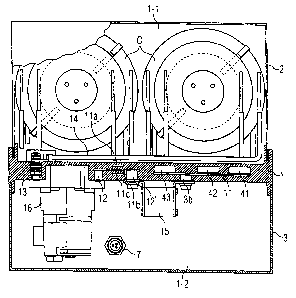
Figure 1 A shows a schematic plan view of a module, which has a molded body 1
as a
carrier platform, a first hood 2, and a second hood 3. The first hood 2 is
preferably formed from
metal. The second hood can be formed from metal or plastic.
Between the molded body 1 of the carrier platform and the first hood 2, there
is a first
module area 1-1, which is preferably hermetically tightly closed and
preferably holds capacitors.
Between the molded body I and the second hood 3, there is a second module area
1-2. Both
module areas are electrically connected to each other and to phase busbars 41,
42, 43 in part
through the carrier platform, by means of electrical lead-throughs, not
visible here, and supply
lines wherein they are mechanically separated from each other by the molded
body 1 of the
carrier platform. The phase busbars 41, 42, 43 are embodied here as three
parallel copper ribbon
lines.
The phase busbars can be formed as copper rails. Preferably, they have a width
of 30 mm
and a thickness of 15 mm. In this way, a sufficient current carrying capacity
is achieved (720 A at
50 Hz as the nominal power) and the copper rails are suitable for a maximum
total power of 500
kvar electrical reactive power. This means that in a modular construction of
several power-factor
P20040225 US N translation
CA 02567902 2006-11-23
11
correction modules connected one after the other, up to five such modules can
be connected in
parallel, wherein each module has an electrical output of 100 kvar. In other
embodiments, the
thickness can also equal only 10 mm or 5 mm.
For phase shifter modules, in which a parallel circuit of several modules is
not provided,
it is sufficient when the busbars have a smaller cross section of, for
example, 30 mm in width
and 5 mm in thickness.
The geometric dimensions are not limited to the above-mentioned numerical
values,
instead one can also consider copper rails, whose width or thickness differs
from the mentioned
numerical values, but whose cross-sectional surface area corresponds
approximately to the values
described here. In principle, the current carrying capacity scales with the
cross-sectional area.
That is, when the cross section doubles, the busbar can also carry twice the
current.
The cross section should preferably not fall below 5 x 20 mm2, corresponding
to a current
carrying capacity of approximately 160 A.
A part of a first 41, a second 42, and a third 43 phase busbar is embedded in
the molded
body 1.
The molded body can preferably be formed so that, in addition to one or more
busbars,
other metallic elements, for example, lead-throughs or inserts, can also be
embedded in this
body. Furthermore, the molded body can be covered with a hood, which engages
in a groove
arranged in the molded body. To guarantee the permanent sealing of the hollow
spaces formed by
the molded body or by the entire carrier platform together with covering hoods
in sufficient
dimensions, it is advantageous if the coefficients of longitudinal expansion
of the different
involved materials are matched to each other.
The production of the molded body can include, in particular, reinforcing
glass (for
example, E-glass fiber), as well as a matrix made from largely unsaturated
polyester or vinyl
ester as components. The molded body can also contain a portion of mineral
fillers.
It is further advantageous if the CTI value is greater than 600. Here, CTI is
the
abbreviation for the term "Comparative Tracking Index." CTI is the comparison
number for the
formation of creepage paths. Insulation materials no longer fulfill their
insulating purpose when
creepage paths are created for the current due to contaminants or moisture on
the surface. CTI is
the maximum voltage - measured in volts - at which 50 drops of contaminated
water does not
cause the formation of creepage paths on the insulation material. This test is
defined in IEC 112.
In addition, it is advantageous if the carrier platform or the molded body
satisfies the
fire-safety standard NFF 16 101/102 with relevant classification.
The mentioned requirements can be fulfilled in an especially economical way
through the
use of a fiber-composite material, for example, with the designation "glass
fiber-reinforced
polyester." Especially preferred is a material that fulfills the requirements
for SMC (= Sheet
P20040225 US N translation
CA 02567902 2006-11-23
12
Molding Compound) or BMC (= Beetle Molding Compound). For a long-lasting
sealing bond
between metal and plastic, wherein here, in particular, a metal hood is used
on one side of the
platform, it is important that the coefficients of longitudinal expansion of
the materials involved
match. For a more detailed explanation of the matching of the coefficients of
longitudinal
expansion, the following table lists examples of information for coefficients
of longitudinal
expansion for possible materials, which are not all-inclusive:
Material Coefficient of longitudinal expansion a(10"6/K
Steel 13
Brass 18
Copper 16.8
Reinforced glass 5-8
Polyester resin 30-45
In a first embodiment of the platform, it is covered with a steel hood. For
the molded
body, a mixture made from polyester resin and reinforced glass in the form of
a composite
material is selected, wherein 30% resin and 70% reinforced glass is contained
in the material. If
one assumes that the resin has a coefficient of longitudinal expansion a of 35
x 10-6/K and the
reinforced glass has a coefficient of longitudinal expansion of 6 x 10⁻⁶/K,
then this produces a
coefficient of longitudinal expansion for the composite material of
approximately 14 x 10-6/K.
In another expansion form of the carrier platform, the coefficient of
longitudinal
expansion can be adapted to a busbar (copper line). Here it is useful to use a
mixture of 50%
resin and 50% reinforced glass, wherein, for the resin, the relevant value for
a coefficient of
thermal expansion a is 30 x 10-6/K and for the reinforced glass the relevant
value for a coefficient
of thermal expansion is 5 x 10⁻⁶/K. Then a composite material is obtained with
a coefficient of
longitudinal expansion a of approximately 10-6/K.
For further explanation, reference is made to the graphical representation in
Figure 17.
There the expansion coefficient of a composite material is shown as a function
of a glass content
percentage in the composite material. The composite material also contains a
resin content,
wherein for two different resin materials, the dependency is indicated by the
glass content for a
composite material produced with the corresponding resin. Figure 17 shows a
curve A for a first
resin composition and a curve B for a second resin composition. The two resin
compositions
differ by their coefficient of longitudinal expansion in the pure, i.e., in
the glass-free state.
The graphical representation shows that, in an especially preferred way, the
setting of the
expansion coefficients is to be implemented by adding a glass portion in the
composite material
P20040225 US N translation
CA 02567902 2006-11-23
13
by means of an assumed linear relationship between the glass content and
expansion coefficient
a. In addition to the glass content, another degree of freedom exists in the
selection of a suitable
resin from an entire group of available resins. Only two different resin
materials are explained in
Figure 17 as examples.
It was also found that resins with a relatively low longitudinal expansion
tend to produce
rather brittle material behavior and thus lead to the formation of hairline
cracks (c~ curve A).
The inverse applies for resins with a somewhat greater longitudinal expansion
(cf. curve B), so
that the tendency to form hairline cracks is rather small. Thus, according to
the requirements, if
necessary, resins with greater coefficients of longitudinal expansion are
preferred.
On the other hand, for process-specific reasons alone, an exact matching of
the
coefficients of longitudinal expansion to another material embedded in the
molded body cannot
be realized completely. However, an adequate matching of the coefficients of
longitudinal
expansion is sufficient, i.e., a small difference between the coefficients of
longitudinal expansion
of the molded body on one hand and the coefficient of longitudinal expansion
of the steel cap,
the brass insert, or the copper rails on the other is definitely allowed.
In an especially preferred embodiment, a glass content of 27% is used together
with a
suitable resin. A platform or molded body produced with such a glass content
has a coefficient of
longitudinal expansion a of approximately 23 x 10-6/K. Thus a mismatch of 10 x
10"6/K is
produced for steel material, of 5 x 10"6/K for brass material, and of
approximately 6 x 10"6/K for
copper material. Such a mismatch corresponds to a preferred embodiment of the
carrier platform.
If necessary, the mismatch can also be greater, for example, the platform can
also have a greater
coefficient of longitudinal expansion.
The use of a relatively low glass content, which is, in particular, less than
that which
would be necessary for setting a coefficient of longitudinal expansion < 20 x
10-6/K (cf. here
Figure 17), is especially advantageous for forming very intricate structures
as integral
components of the molded body. In particular for the shaping of fine ribs,
which stand upright on
the carrier platform and which are used for insulation between components, a
relatively low glass
content is advantageous.
It is especially preferred, in the matching the coefficients of thermal
expansion, to attempt
to achieve the best possible matching to the copper material. The steel
material is relatively
non-critical, because an elastic adhesive, which can easily compensate for
small differences in
longitudinal expansion, can also be provided, if necessary, between the
platform and the steel
cap. For matching the coefficients of thermal expansion to the brass material,
attention must be
paid that the brass material is present in the preferred embodiments of the
platform only in the
form of small inserts, so that here at least small differences in the
coefficient of thermal
expansion are relatively non-critical. Busbars extending along a relatively
long distance of the
P20040225 US N translation
CA 02567902 2006-11-23
14
platform or the molded body have a different behavior, because infinitesimal
differences in
longitudinal expansion add up to a marked difference in longitudinal expansion
or difference in
length when the temperature increases.
In an especially preferred embodiment of the carrier platform, the glass
content in the
fiber-composite material equals between 25 and 35 wt.%.
In this way, the glass content is preferably selected somewhat lower than the
glass content
that would be necessary for a given polyester resin and thus a fixed
coefficient of longitudinal
expansion of the polyester resin in light of the remarks on Figure 17, in
order to achieve an exact
equalization of the coefficients of thermal expansion to the copper material.
Through the reduced
glass content, an improved flowability of the plastic to be processed is
achieved, with which
intricate configurations of the molded body are possible. In particular, the
formation of several
narrow upright ribs close to one another can be simplified.
In one variant of the hood 2, openings 8 are formed, which can be provided as
impregnating openings or as openings for receiving mounting elements or other
elements, e.g.,
connections of an external control device. The openings for mounting
components are preferably
arranged in at least one hood wall or in opposite side walls of the hood.
However, the
components can also be connected rigidly to the carrier platform.
The hood 2 preferably has perforated brackets, which can be angled. The
brackets are
fixed mechanically to the molded body 1, e.g., by means of screws. The
corresponding interfaces
can also be gas-tight or oil-tight, if necessary. The hood 3 can also be fixed
to the molded body
using analogous means and methods. Alternatively, at least one of the hoods or
also both of the
hoods can be removed.
Figure 1B shows a schematic plan view of the module from Figure lA. In an
opening
arranged in the second hood 3, there is a control terminal 7 for controlling a
switching device 16
from Figure 2. The phase busbars 41, 42, and 43 project from the carrier
platform, which is not
visible here, on both sides, and have first external terminals 51, 52, 53 and
also second external
terminals 61, 62, 63. The external terminals of the phase busbars are provided
with bores or
openings for receiving attachment elements.
In Figures 1 A and I B, examples of geometric dimensions of the power-factor
correction
module are also to be found. According to Figure lA, the height hl of the
volume enclosed by
the hood 2 equals approximately 260 mm. The total height h of the arrangement
equals
approximately 400 mm. The width b of the module equals approximately 360 mm
and the depth t
equals approximately 260 mm. In total, a volume of approximately 39 1 is
produced, which is
necessary for a phase-shifting module with an electrical reactive power of 100
kvar.
Figure IC shows another schematic side view of the module from Figure lA.
Inserts 18c
are formed in recesses 10 of the side wall of the molded body 1. The inserts
18c are preferably
P20040225 US N translation
CA 02567902 2006-11-23
threaded bushings, which are used for receiving fastening elements and can be
connected to
attachment angles, e.g., by means of screws.
The external walls of the molded body are preferably formed at a right angle
to the
(longitudinal) axis or base surface of the molded body, at least in the insert
areas, i.e., these areas
do not have bevels. This shaping has advantages when attachment angles are
attached.
In Figure 1 D it is indicated that all of the power electronic components of
the module can
be arranged in a single, preferably enclosed, hollow space 20.
The hood 2 is preferably mounted to the molded body 1 by means of retaining
screws
embodied as self-cutting screws. The molded body can have corresponding
mounting points, e.g.,
in the form of suitable configurations, which as used for attaching the hood
2. The attachment
points of the molded body can have openings for receiving retaining screws,
which preferably lie
opposite the perforated mounting brackets of the hood.
Furthermore, in the molded body 1 there is a recess 18, into which the hood 2
projects.
The recess 18 is preferably formed as a peripheral shaft (or a peripheral
groove) suitable for
receiving an adhesive or sealant that seals the molded body-hood interface. A
rubber piece or a
rubber ring can also be used as a sealant, which, compared with a cast part,
has the advantage
that the hood is well sealed on one hand (i.e., is gas or oil tight) and it is
removable on the other
hand.
This interface can be used as a designed break point, with the removing force
of the
retaining devices named above for the hood being selected so that the hood
tears when a defined
overpressure threshold is exceeded.
The functional unit of a module can be designed, e.g., as a phase shifter or
as a power
mains filter. In a phase shifter, the power capacitors preferably form a delta
connection, whose
nodes can each be connected to a phase busbar 41-43, preferably via a safety
device 15 or
switching device 16, cf. Figure 2. The power capacitors can alternatively be
interconnected in a
star arrangement, with their free connections each being able to be connected
to a phase busbar
or to the corresponding circuit branch of the functional unit.
The safety device 15 preferably represents a short-circuit safety device.
Figure 2 shows the block circuit diagram of a functional unit suitable for
power-factor
correction or for filtering power mains harmonic oscillations. The capacitors
C (power
capacitors) are interconnected into a triangle, with each electrical node of
the delta circuit being
connected to a circuit branch allocated to the corresponding current phase.
The circuit branches
each have a safety device 15, a switching element, which can be, e.g., a
switch contactor, for a
three-phase switching device 16, and a three-phase current choke L, with the
named components
being connected one after the other in the circuit branch. The circuit
branches are each connected
to a phase busbar 41, 42, or 43 integrated in the module. PEN designates a
neutral conductor.
P20040225 L)S N translation
CA 02567902 2006-11-23
16
In a preferred variant, discharge resistors R and discharge inductors L' are
connected in
parallel to the capacitors C. Either the discharge resistors R or the
discharge inductors L' can be
integrated in one power capacitor.
As an alternative, the power capacitors can also be interconnected in a star
arrangement in
a power mains filter and connected to the corresponding circuit branches.
A monitoring unit not shown here is connected to the corresponding current
conductor for
monitoring the phase shift cp between current and voltage on the power mains-
operator side of the
power network, which is shown on the left, e.g., in the figure. When a given
threshold of the
phase shift is exceeded, this monitoring unit connects the functional unit of
a power-factor
correction module to the power network by activating the switching device 16.
As an alternative to the switch contactor in the functional unit of a module,
a different,
especially a dynamic switching device, e.g., a thyristor module for a dynamic
power-factor
correction or for separating the functional group from the power mains, can be
provided. Instead
of a connector switch with three switching elements in each circuit branch of
the functional unit,
a preferably "naked" semiconductor switch in the form of a thyristor can be
provided.
The components shown in Figure 2 (capacitor and inductor) can form a
functional group
of several interconnected (compact) LC elements in one variant of a power-
factor correction
module, see Figures 3 to 5. Compact means that a component (LC element W I,
W2, W3) is
embodied as a housed or preferably unhoused discrete component with electrical
contacts 31, 32.
The LC elements are arranged in the first or second module area and preferably
each is connected
to a load capacitor CL1, CL2, CL3. The load capacitors CL1, CL2, CL3 can be
formed as separate coil
capacitors or optionally together as a three-phase coil capacitor with two
insulating layers. Each
load capacitor can be formed by several parallel capacitors.
A power-factor correction circuit can have modularized components, which each
include
several circuit elements, preferably a combination of a capacitor and an
inductor. Such an LC
element can be realized by a preferably dry capacitor coil optionally wound
concentrically around
a central column.
The delta-star circuit shown in Figure 2 with capacitors C and inductors L can
be replaced
in principle by a circuit of compact LC elements. An LC element is preferably
allocated to one
current phase.
Figure 3 shows schematically in a cut-out, a functional unit that includes
three electrically
interconnected, compact LC elements W1, W2, W3, which are each connected to a
load
capacitor. An LC element preferably has a magnetic circuit. The LC elements
are interconnected
in a symmetric base circuit with three phase connections L1, L2, L3. Several
LC elements
preferably connected in parallel to each other with a load capacitor can be
provided per current
phase.
P20040225 US N translation
CA 02567902 2006-11-23
17
In an advantageous variant, an LC element can be formed as an LC coil with a
UU
magnetic circuit (i.e., with two joined U-shaped magnet cores), which is
connected to an external
capacitive load. The LC coil here is preferably formed in two parts with two
LC sub-coils W 1 a,
W 1 b connected in series, see Figure 4.
The external capacitive load preferably represents the power capacitor or the
capacitor C
of the module, which is arranged in the first module area. The LC element is
preferably housed
and also arranged in the first module area. In this case, the LC element or
the corresponding LC
coil is preferably oil-impregnated and not self-sealing.
In the molded body of the carrier platform, recesses (caverns) for receiving
LC coils or
other components, as well as other correspondingly shaped depressions or
shafts, can be formed
for holding the U-shaped magnet cores or other components of the module.
An LC element preferably corresponds to a single component, here with four
electrical
terminals (31, 32, 33, 34). The electrical terminals 31 and 32 of a first LC
element W1 are
provided as primary terminals (i.e., system connections in the phase direction
for connecting the
LC element between two current phases). The electrical terminals 33 and 34 of
the first LC
element Wl are provided as secondary terminals for contacting to a load
capacitor CLI.
Analogously, a second and a third LC element W2, W3 also have primary and
secondary
terminals.
The primary terminals are connected to the phase terminals L1, L2, D. The
secondary
terminals are connected to a preferably external load capacitor CL1, CL2, CL3.
The load capacitors
are preferably formed as self-sealing capacitors.
The LC coil involves, among other things, a spiral, wound film capacitor, with
the
beginning and end of the two capacitor films - metal films B 1 and B2 - being
contacted
electrically to four connection points 31, 33 (at the beginning) and 32', 34'
(at the end).
The load capacitor is preferably connected, as shown in Figure 4, at the
beginning of the
film of the first LC sub-coil W 1 a and at the end of the film of the second
LC sub-coil W 1 b. Here,
the end of the metal film B 1 or B 1' (B2 or B2') facing inwards is designated
as the end of the
film. The end of the metal film facing outwards is designated as the beginning
of the film.
Analogously, a first primary termina131 is connected to the beginning of the
metal film B2 and a
second primary terminal 32 to the end of the metal film B2.
By suitable selection of the L/C ratio, a resonance frequency of, e.g., 250
Hz, can be set
by connecting the LC element W 1 to the load capacitor CL1.
In an advantageous variant, an LC element can be built on a magnet core, e.g.,
made from
magnetic iron, see Figure 4.
An LC element W 1 shown schematically in Figure 4 is formed by a series
circuit made
from two LC sub-coils W l a, W l b.
P20040225 US N translation
CA 02567902 2006-11-23
18
The first LC sub-coil W 1 a includes two electrically conductive films - metal
films B I and
B2 - which are electrically insulated from each other by a dielectric film 93.
In this example, each
film consists of a three-layer metal film, preferably Al film. The dielectric
films 93 are here
formed with two layers.
The composite layers of alternately arranged dielectric films 93 and metal
films B1 or B2
are wound in a spiral around a central column 92. These composite layers can
have an additional
electrically insulating layer 94 pointing outwards and/or inwards towards the
central column.
The central column 92 is preferably arranged with a positive fit on a magnetic
core. In
this example, the central column 92 of the first LC sub-coil W 1 a is arranged
around a first leg of
a (doubly slotted) annular core, with the annular core being formed by two U-
cores 91, 91' and
magnetic inserts 98 arranged in-between. An annular core formed in this way is
also designated
as a UU core.
The second LC sub-coil W 1 b is built essentially like the first LC coil W 1 a
and arranged
about a second leg of the annular core (UU core) lying opposite the first.
The insert 98 is placed in the interior of the central column 92. The insert
98 and the UU
core each have different magnetic permeability.
All of the layers of an LC coil, especially the metal foils B1, B2, the
dielectric films 93,
and the insulating layers 94 can each be composed of, in principle, one layer
or several partial
layers. For example, in Figure 4, the insulating layer 94 and the dielectric
film 93 are formed
with two layers.
All of the windings of the first metal film B 1 of the LC sub-coil W 1 a are
connected to an
internal terminal 32', which is arranged on a first end of the LC sub-coil W 1
a. All of the
windings of the second metal film B2 of this LC sub-coil are connected to an
internal terminal
34', which is arranged on a second end of the LC sub-coil W 1 a. Analogously,
from one end the
first metal film B 1' of the second LC sub-coil W 1 b is connected to an
internal terminal 33' and on
the opposite end its second metal film B2' is connected to an internal
terminal 31'.
On one side of the component, the internal terminals 32' and 33' of the two LC
sub-coils
W 1 a, W 1 b are interconnected by means of an electrical terminal 96. On the
other side of the
component, the internal terminals 31' and 34' of the two LC sub-coils W 1 a, W
1 b are
interconnected by means of an electrical termina197.
Therefore, the first metal foil B 1 of the first LC sub-coil W 1 a is
connected electrically in
series with the first metal film B 1' of the second LC sub-coil W 1 b. The
second metal film B2 of
the first LC sub-coil W 1 a is correspondingly connected electrically in
series with the second
metal film B2' of the second LC sub-coil Wlb.
P20040225 US N translation
CA 02567902 2006-11-23
19
The wiring of the individual LC sub-coils W 1 a, W 1 b in an LC element W 1 is
shown
schematically in Figure 5. Three LC elements built according to Figure 5 can
form one star
circuit.
Figure 4 shows that the LC element W 1 can be formed as a housed component
with a
housing 95. The housing 95 can be prepared, e.g., in the form of an aluminum
cup with a cover
with the external terminals 31 to 34.
In principle, an LC element can consist of a single LC coil formed as a
compact element.
The magnetic core can be formed axially.
The functional principle of an LC coil, wherein a capacitor coil acts
simultaneously as a
choke coil, consists in the fact that a capacitor coil is wound around a
magnetic core, for
example, an iron core, so that the capacitor coil simultaneously represents a
sufficiently high
inductance. The inductance is achieved in that the current must flow through
all of the windings
of the capacitor coil. Thus, it must flow several times around the iron core,
with which the
windings of a choke coil are simultaneously formed. The construction shown in
Figure 4
distinguishes itself through low weight and low costs.
In Figure 6, an example of a power-factor correction module is shown in a
schematic
cross section perpendicular to the axes of the phase current conductors 41-43.
In this module, a
first hollow space or a first module area 1-1 is formed between a first hood 2
and the molded
body 1. The first functional group, which is composed of or includes power
capacitors, is
arranged in this hollow space or area. A second hollow space or a second
module area 1-2 is
formed between a second hood 3 and the molded body 1. The second functional
group, which
includes safety devices 15 and a switching device 16 with a preferably
multiple-pole control
terminal 7, is arranged in this hollow space or area. The opposing sides of
the molded body 1(in
Figure 6 the top side and the bottom side) each have a recess for receiving
components.
The lead-through 13 is connected on one side to the first functional group by
means of a
busbar 14. On the other side, the lead-through 13 is connected electrically to
the second
functional group. The two functional groups are electrically interconnected by
means of an
electrical lead-through 13. The lead-through 13 is here preferably hidden to a
large extent in the
molded body 1 of the carrier platform. The electrical lead-through 13 is here
allocated to the third
current phase. Preferably, there is a separate electrical lead-through 13 for
each current phase.
The separate electrical lead-throughs 13 can provide, in particular, an
electrical terminal
between a capacitor area, which is also designated as a first module area and
which is preferably
hermetically tightly sealed and therefore difficult to access, and a second
module area, which is
provided with a removable hood and therefore easy to access and which is
allocated to the
switching devices.
P20040225 US I i transiation
CA 02567902 2006-11-23
In principle, electrical lead-throughs, parts of the current conductors, and
also other metal
components optionally integrated in the molded body can also be plugged in. A
module
component available as a plug element can also be formed with multiple parts
and can include,
e.g., spring-like elements, such as contact springs.
Components, i.e., safety devices 15, capacitors C, and switching elements are
interconnected electrically via supply lines. A first supply line includes a
busbar 11 a, 11 b, 11 c, or
14 and vertical contact elements 12', 12".
A second supply line includes a current conductor 11 and a vertical contact
element 36
and is used for electrical terminal of the third phase current conductor 43 to
the safety device 15.
An example construction of a supply line is shown in Figure 7 in perspective
view.
The safety device 15 visible in Figure 6 is connected by means of vertical
contact
elements 12, 12' on one side to the busbar 11 and on the other side to the
busbar 11 b. The busbar
11 b is further connected to a switching element of the switching device 16 by
means of a vertical
contact element 12". The corresponding switching element of the switching
device 16 is
connected with its other contact to the electrical lead-through 13.
The busbars 11 a, 11 c of the first supply lines are connected to other safety
devices
allocated to the first and second current phase and not visible in this figure
and to other switching
elements of the switching device 16 not visible in this figure, wherein the
other switching
elements are connected electrically to the corresponding power capacitors or
with the
corresponding winding of a three-phase power capacitor.
Supply lines, especially the busbars 11 and 11 a-11 c, can be hidden
completely in the
molded body 1. The busbar 141ies bare in the first hollow space in this
variant.
In the carrier platform, for multiple or three-phase applications, preferably
several
metallization levels are provided, in Figure 8 three, ME1, ME2, and ME3 (=
levels for the
electrical lines), which are used as wiring levels for wire-free connection of
components to one
another or to phase busbars. Two metallization levels are separated by a
dielectric layer made
from fiber-composite material.
In addition, a power-factor correction unit is disclosed, in which several
electrical
components are integrated, for example, capacitors or also safety devices,
switching contactors,
or thyristors, and if necessary, also safety devices. At least a few of the
electrical components are
interconnected without wires. Such a wire-free connection is realized, for
example, with one of
the carrier platforms disclosed here, in which rigidly installed busbars are
provided. The
wire-free connection of electrical components has the advantage that the
assembly expense for
producing the device or the current compensation module can be reduced, by
means of which
production costs can be reduced.
P20040225 US N translation
CA 02567902 2006-11-23
21
Depending on the application, the hood can be closed tightly with the molded
body, e.g.,
through adhesion or casting, or else embodied as a removable part. A removable
hood has the
advantage that components arranged underneath can be easily replaced when
there is a fault.
In Figure 6, the first hood 2 projects into the recess of the molded body 1
and is fixed
there by casting. A permanent seal adhesion or sealing between the hood,
especially a metal
cover, and the molded body can be achieved by matching their coefficients of
thermal expansion.
The coefficient of thermal expansion of the casting is preferably also
matched. Matching the
coefficients of expansion means that their relative difference does not exceed
a certain value
defined by the application.
The second hood 3 is set on the collar of the molded body 1 and, in principle,
is
removable. In principle, it is also possible to close the second hood tightly
to the molded body.
The first hood 2 can also have a removable construction if the exchangeability
of the
capacitors is desired. In this case, a capacitor coil can be equipped, e.g.,
with plug contacts.
In Figure 7, supply lines are formed as contact strips, with vertical contact
elements 12',
12" are fixed to the busbars 11 a, 11 b, and 11 c preferably through welding.
The vertical contact
elements 12', 12" represent hollow cylinders, with a hollow cylinder
preferably having an internal
thread. The vertical contact elements can also be composed of brass.
The vertical contact element 12' of a certain supply line is allocated
according to Figures
6, 9 to a first installation site, which is provided for the safety device 15.
The vertical contact
element 12" is allocated to a second installation site, which is provided for
the corresponding
switching element of the switching device 16.
Figure 7 shows that the busbars 11 a, 11 b, and 11 c of different first supply
lines can be
arranged in different metallization levels. Here, the vertical contact
elements 12" of different
supply lines have different heights and are designed so that they are
completely enclosed in the
molded body 1 of the carrier platform up to their top side. It is also
possible for the vertical
contact elements to project partially from the platform and carry, e.g.,
additional mounting
devices.
Each of the parallel first supply lines forms a separate contact strip. The
busbars of
different contact strips are preferably arranged in different metallization
levels and allocated, for
example, to a certain current phase. An arrangement of different supply lines
in parallel levels
allows a compact connection in the module, wherein, in particular, the supply
lines allocated to
the different current phases are run one above the other and can even cross
each other in the
vertical projection, with the risk of short circuits being prevented by the
intermediate dielectric
layer.
P20040225 US N translation
CA 02567902 2006-11-23
22
One busbar can have branches and in this way more than only two internal
terminals or
vertical contact elements. The busbar of one supply line can also be welded,
e.g., to the busbar of
another supply line or a phase busbar.
Figure 9 shows a schematic cross section of the module from Figure 6 in a
plane running
parallel to the direction of the phase busbars 41-43 and vertical to the plane
in which the axes of
the phase busbars lie. In this variant, two safety devices 15 per current
phase connected to the
same metallization level, are provided.
Figure 10 shows a schematic cross section of the module from Figure 6 in a
plane running
parallel to the plane in which the axes of the phase busbars lie.
Figure 10 also shows separating connectors 100, which are integrated in the
carrier
platform and are preferably molded in one piece from the fiber-composite
material of the molded
body. These separating connectors 100 run parallel to each other and each
lengthen the creepage
distance between two connections that belong to different contactor switches
16.
Figure 11A shows another module in schematic cross section perpendicular to
the axes of
the phase busbars. Figure 11B shows this module in schematic cross section
parallel to the axes
of the phase busbars. Here, several (in total twelve) capacitor coils, which
are joined into one
capacitor coil package and which form the first functional group of the
module, are arranged in a
first module area. The capacitor coil package is insulated in this variant
from the preferably
metallic hood 2, such that an intermediate space formed between the capacitor
coil package, the
carrier platform, and the first hood 2 is filled, e.g., with a molecular sieve
granule filling. This
filling provides for good thermal coupling of the capacitor coil package to
the hood or for good
dissipation of the heat generated during operation. This filling is also used
for moisture and noise
protection. Other suitable fillers, especially cast bodies or resins or
granules, can also be used as
the filling. The granule filling is shown in Figure 11A by shading.
To dissipate the heat, sheet-metal parts can also be used in addition to the
capacitor coil.
Two inserts 18c are embedded in each of the opposing external walls of the
molded body
1.
In the first module area there is a temperature sensor 81 and an overpressure
sensor 82 for
monitoring the internal pressure. The overpressure sensor 82 or an pressure-
relief switch is
preferably arranged in the area of the hood 2.
The overpressure in the first module area builds up due to self-healing
breakdowns or in
case of overloading due to non-self-healing breakdowns and leads to
corresponding bulging of
the first hood 2. The overpressure sensor is connected to an external control
unit, which outputs a
signal for turning off the functional unit to the switching device 16, e.g.,
via the control terminal
7 from Figure 9, when there is overpressure in the first module area. The
temperature sensor 81 is
allocated to a switching unit, e.g., a temperature switching unit that
separates the functional unit
P20040225 US N translation
CA 02567902 2006-11-23
23
of the module from the power mains, for example, also by means of the
switching device 16,
when there is a thermal overload.
The module can also include, for example, an overpressure tearing safety
device, which
removes the bulging of the hood 2, i.e., the overpressure in the first module
area, e.g., by means
of a membrane or a steel cable for triggering a tearing mechanism when a given
threshold of the
internal pressure is exceeded. The overpressure tearing safety device is
preferably arranged in an
electrical supply or discharge line connected to the capacitor.
The switching device 16 is connected to the lead-through 13 via a supply line
86.
The section A'-A' of the module presented in Figure 11A is shown in Figure
11B. For
discharging the heat of the capacitor coils, cooling sheets can be provided. A
construction space
77a for a compact, preferably oil-impregnated LC element with load capacitor
is provided.
Therefore, the construction space is preferably closed oil-tight.
An example construction of the lead-through 13 is shown in Figure 13A.
Figure 12A shows the construction of internal terminals of the phase busbars
41, 42, 43.
A busbar 1a is welded on one end to the phase busbar 41. On its opposite end,
the busbar 1a is
welded to a vertical contact element lb. The phase busbars 42 and 43 are
similarly welded to
busbars 2a or 3a. The busbars 2a and 3a each have a vertical contact element
2b or 3b.
The busbars la, 2a, 3a run in a projection plane perpendicular to the phase
busbars 41 to
43. Here, the busbars la, 2a, and 3a - as indicated in Figure 12B - are formed
so that they run
partially (especially in the intersecting areas) in a different metallization
level than the phase
busbars and do not contact the other phase busbars. The busbars la to 3a can
have, e.g., a spacer
101 or a socket, which is arranged on the corresponding phase busbar and is
connected rigidly to
this busbar or to the busbar la, 2a, 3a.
The vertical contact elements lb to 3b preferably have different heights, with
each
vertical contact element 1b, 2b, or 3b guaranteeing the connection to a
separate metallization
level corresponding to the current phase. However, the vertical contact
elements lb to 3b can
also have the same height and can each have a contact area, which is
accessible, e.g., from the
surface of the molded body and is preferably also suitable for mounting
components. These
vertical contact elements can form, for example, internal terminals of the
carrier platform for
connecting a component, preferably a safety device 15.
The configuration of phase busbars can be transferred without additional means
to other
busbars provided, e.g., as supply lines.
Figure 13A shows the lead-through 13, which is partially embedded in the
molded body 1
of the carrier platform. The lead-through 13 has a plug 83a and a bushing 84
embedded in the
molded body 1 of the carrier platform. On the plug 83a there is a bushing 83b,
to which the
busbar 14 used as a supply line to the capacitors or to the first module area
is connected. The
P20040225 US N translation
CA 02567902 2006-11-23
24
bushing 83b is preferably a round plug contact, which allows the later
replacement or repair of
capacitor coils.
The bushing 84 of the lead-through 13 is connected electrically and fixed
mechanically to
the supply line 86 arranged in the second module area and connected to the
switching device 16
by means of a screwed threaded bolt 85.
Figure 13B shows how the first phase busbar 41 can be connected to the busbar
I 1 by
means of a screw 44. In the molded body 1, a recess 49 is provided for forming
direct contacts on
the phase busbar 41.
In a schematic view, Figure 14 shows a phase shifting device with a modular
construction. There is a switch cabinet 150, which can be composed of, for
example, metal,
which offers sufficient space for several individual phase shifter modules I
10, 111. The required
number of phase shifter modules 110, 111, which is based on the electrical
reactive power to be
processed, are arranged one above the other and fixed by means of mounting
elements 141 on
mounting rails 132, 131. The mounting elements 141 can preferably be fixed in
the inserts
arranged in the individual phase shifter modules in the housing. The
attachment is preferably
realized by means of screw connections.
The individual phase shifter modules 110, 111 are also interconnected by means
of
contact elements 120. The contact elements 120 interconnect, in particular,
the phase busbars 41,
42, 43. In particular, it is advantageous to provide the contact elements 120
for a screw
connection with the phase busbars.
Figures 15 and 16 show a safety design in a schematic representation. The
molded body 1
of a carrier platform is sealed on the top side by means of the hood 2 (only
shown schematically
and with dashed lines). On the top side, a capacitor C is arranged in a
hermetically tight part of
the arrangement. Preferably, a leakage rate of 4 to 6 x 10"6 mbar x Llsec is
achieved.
This configuration involves, for example, a high-power capacitor. The
capacitor includes
a capacitor coil 170 which is wound on the outside of a central column 160.
The central column
is hollow on the inside and provides space for a temperature sensor 81. The
temperature sensor
81 here is located approximately in the center of the capacitor, which is also
the place where the
temperature of the capacitor is greatest when current is flowing. This area is
also called a "hot
spot." By placing the temperature sensor 81 in the vicinity of the hot spot,
the safety mechanism
can be triggered extremely quickly when a certain temperature is exceeded. The
resulting heat
still must not pass through time-delaying paths in order to be led from the
heat source to the
temperature sensor 81.
The temperature sensor 81 is coupled by means of a line 180 to a switching
device 16,
which is provided here only for one example phase P and which connects the
phase P to the
capacitor. The switching device 16 is essentially composed of a separating
switch, which
P20040225 US N translation
CA 02567902 2006-11-23
separates the capacitor C from the phase P and thus from the power mains when
the switching
device responds. When the temperature sensor 81 is triggered, it transmits a
signal via the line
180 to the switching device 16 in order to switch off the capacitor in the
case of a fault.
In addition, a device is attached to the bottom side of the molded body, that
is, in the not
necessarily hermetically tight part of the device. However, the overpressure
sensor 82 can also be
arranged at any other suitable position, especially in the interior of the
upper volume of the
arrangement or also in the hood 2.
The coupling of the overpressure sensor 82 is realized by means of an insert
190, which is
molded from plastic material or from composite material and thus is sealed
against the plastic
material. In addition, the overpressure sensor 82 includes a pressure sensor
210, which is pushed
into the insert and which is sealed by means of a sea1200. The entirety of the
molded body 1,
inset 190, pressure sensor 210, and seal 200 thus seals the top part of the
arrangement from the
bottom part, i.e., from the bottom side of the platform.
The overpressure sensor 82 is also coupled to the switching device 16 by means
of a line
180 and can thus switch off the capacitor from the phase P when an
overpressure appears.
If necessary, another safety device 15 can be connected in series to the
switching device
16.
The described devices were explained based on only a few embodiments, but are
not
limited to these.
All of the aspects and features of the devices can be combined arbitrarily
with each other
and also with other known measures, e.g., for attaching the components or for
realizing
lead-through and contact elements. The number of mentioned components and the
separate
module areas to be formed can vary.
List of reference symbols
1 Molded body
1 a Busbar
lb Vertical contact element
2 First hood
2a Busbar
2b Vertical contact element
3 Second hood
3a Busbar
3b Vertical contact element
7 (Multiple-pole) contactor control connection
8 Opening
P20040225 US N translation
CA 02567902 2006-11-23
26
Recess
11 Busbar
lla, llb, llc Busbar
12, 12', 12" Vertical contact element
13 Electrical lead-through
14 Busbar
Safety device
16 Switching device (contactor switch)
18 Recess in the molded body
18c Attachment element (insert)
Hollow space
21 Attachment bracket
22 Bore in the attachment bracket 21
31, 32 Primary terminals of an LC element W 1
33, 34 Secondary terminals of an LC element Wl
31', 33' Internal terminals of an LC sub-coil (Wlb) for connecting another LC
sub-coil
(Wla)
32', 34' Internal terminals of an LC sub-coil (WIa) for connecting another LC
sub-coil
(Wlb)
41 First phase busbar
42 Second phase busbar
43 Third phase busbar
44 Screw
49 Recess in the carrier platform
51 External terminal of the first phase busbar
52 External terminal of the second phase busbar
53 External terminal of the third phase busbar
61 External terminal of the first phase busbar
62 External terminal of the second phase busbar
63 External terminal of the third phase busbar
77a Construction space for an inductor
81 Temperature sensor
82 Overpressure sensor
83a Plug
83b Bushing
84 Bushing
P20040225 US N translation
CA 02567902 2006-11-23
27
85 Threaded bolt
86 Supply line
91, 91' U-core
91 a, 91 a' End face of core leg
92 Core sleeve
93 Dielectric film
94 Insulating layer
95 Housing of a compact LC element W l
96 Electrical terminal between B 1 and B 1'
97 Electrical terminal between B2 and B2'
98 Insert made from magnetic material
100 Separating connector
101 Spacer
110, 111 Phase shifter module
120 Contact element
131, 132 Mounting rail
141 Attachment element
150 Switch cabinet
160 Central column
170 Capacitor coil
180 Line
190 Insert
200 Seal
210 Pressure sensor
B t First metal film
B2 Second metal film
C Capacitor
CL1, CL2, CL3 Load capacitor
L Inductor
L' Discharge inductor
R Discharge resistor
L1, L2, L3 Connections of the current phases in the three-phase system
W 1, W2, W3 LC element
W l a First LC sub-coil
W l b Second LC sub-coil
PEN Neutral conductor
P20040225 US N translation
CA 02567902 2006-11-23
28
ME 1 First metal layer
ME2 Second metal layer
ME3 Third metal layer
h, h 1 Height
b Width
t Depth
p Phase
A First resin composition
B Second resin composition
G Glass content
a Coefficient of expansion