Note : Les descriptions sont présentées dans la langue officielle dans laquelle elles ont été soumises.
CA 02567974 2006-11-23
WO 2005/123555 PCT/EP2005/005368
METHOD AND APPARATUS FOR WINDING UP CORELESS AND SOFT-
CORE ROLLS OF FILM MATERIALS
BACKGROUND OF THE INVENTION
This invention refers to the production of soft-core and coreless rolls of
films or continuous band of thin sheet material such as stretchable and heat
shrinkable plastic films, or bands in paper or different materials, which are
con-
tinuously fed, embossed and wound or rolled up onto a spindle to form a roll
in a
controlled mode.
More precisely, the invention relates to a method and an apparatus for
lo producing soft-core and coreless rolls of a film material namely devoid of
a sup-
port tube, or,provided with a support soft tubular core for winding up the
film. For
thepurpo"se,"of,tho",present invention, "soft-core" means a,core of soft or
flexible
materiai, suW~a ~as paper and the like, for winding up the film, compared to
rigid
cardboc~rd'corzs ,1'
is The invention is also directed to a coreles6= or'soft-core roll of film
material
~..
obtained according to the claimed method.
Although the formation of coreless or soft-core rolls for example of plastic
film, currently has a specific use in the packaging or for winding palletised
loads
with a pre-stretched film, this invention is nevertheless applicable to the
forma-
20 tion of coreless rolls or provided with a soft tubular core, by any type of
extensi-
ble or heat-shrinkable plastic films, paper or different sheet material
depending
upon the circumstance and use.
It is well known that heat-shrinkable or extensible plastic films wound into
roll, are normally used for rolling up and packaging palletised loads or
goods.
CA 02567974 2006-11-23
WO 2005/123555 PCT/EP2005/005368
2
The use of extensible and heat-shrinkable plastic films is widespread in
the packaging field, in that it offers the possibility of adequately
consolidating any
type of palletised load or packaged goods, by simply winding around and making
the film adhere to the load or good with a certain tension.
Furthermore, the use of pre-stretched plastic films proves to be advanta-
geous in that pre-stretching gives the plastic material greater resistance,
and in
that a pre-stretched film can be wound around a load, especially delicate
loads
or goods, without causing excessive stress.
However, in winding up rolls of film, and in their subsequent use, several
io problems arise which have been variously tackled and variously solved in
the
past.
In fact, with usual smooth films, it is difficult to wind coreless rolls or to
wind up the film on a soft tubular core, which has a stable shape, due to
their
tendency to implode.
Moreover, pre-stretched films or elastically yielding films retain an elastic
memory which over time makes them to shrink in such a way that the outer turns
generate a pressure on the inner turns, deforming and making them adhere to
one another, thereby preventing or making it difficult to properly unwind the
stretched film from a roll.
This problem has been partially solved by suitably embossing the film, for
example by forming a plurality of small pockets, by slightly deforming the
film
against an appropriate toothed embossing drum, trapping the air and preventing
a close contact between the turns of the roll.
An apparatus for embossing extensible film wound up into a roll is de-
CA 02567974 2006-11-23
WO 2005/123555 PCT/EP2005/005368
3
scribed for example in EP-A-0 728 102.
According to this document, the plastic film is made to move, at a con-
stant speed, between a set of drawing rollers connected to a control motor; a
toothed drum embosses the film, before it being wound onto a roll, maintaining
the plastic film under a stretched condition so as to make it frictionally
adhere to
the toothed surface of the embossing drum; the teeth of the embossing drum
cause a partial deformation of the plastic film and the consequent formation
of
small pockets in which air remains trapped during a subsequent winding step of
the roll.
This solution has however a number of drawbacks, such as for example
the difficulty in obtaining evenly wound rolls having a constant diameter; in
fact
the deformation of the film, necessary to form the small embossed pockets for
entrapping the air, tends to generate irregularly distributed internal
stresses, with
the consequent formation of creases in the film during the winding up of the
roll.
is Moreover, since the air remains entrapped in the individual pockets,
without any
possibility of venting, the rolls of film have a final diameter, which is
still consid-
ered to be excessive, in relation to the quantity of wound up film.
Lastly, the winding up of coreless as soft-core rolls by the methods and
apparatuses currently in use, leads to the formation of rolls having very
large di-
2o ameters, with consequent higher storage and transport costs due to the
larger
volume incurred by the same rolls.
US-A-5,003,752 describes a winding up method and an apparatus for roll-
ing up a pre-stretched film around a load, which make use of stretching rolls
each having alternate and intermeshing peripheral ridges, arranged such that
CA 02567974 2006-11-23
WO 2005/123555 PCT/EP2005/005368
4
the ridges on each roll mesh with the grooves on the other roll; the plastic
film in-
troduced between the stretching rolls, is continuously folded in the
longitudinal
direction and forcibly drawn, stretched longitudinally and in the crosswise
direc-
tion; the stretched film emerging from the stretching rolls to be wound around
the
load, is again in a smooth or flat form.
OBJECTS OF THE INVENTION
The main object of this invention is to provide a method and an apparatus
for winding up coreless and soft-core rolls of film materials, whereby it is
possible
to adequately obviate the aforementioned problems, improving both the winding
io and the unwinding of the same film from a roll.
In particular, an object of the invention is to provide a method and an ap-
paratus for winding up coreless and soft-core rolls of film materials, in
particular
plastic films, whereby it is possible to wind a larger quantity of film, while
at the
same time maintaining or reducing the diameter of the roll, compared to conven-
tional coreless and soft-core rolls; therefore, one of the advantages of the
inven-
tion consists in the possibility of reducing the volume required by a roll to
wind up
a same quantity of film, which on average can be as much as 30%, thereby con-
siderably reducing the cost for storage and transportation of the rolls.
A further object of the invention is to provide a method and an apparatus
for winding up coreless and soft-core rolls, which are capable of ensuring an
im-
proved rolling up of the film to obtain rolls substantially free from
irregularities.
Another object of the invention is to provide a method and an apparatus
for winding up films, as mentioned previously, whereby it is possible to
obtain
coreless and soft-core rolls, that is to say rolls without the internal
winding core
CA 02567974 2006-11-23
WO 2005/123555 PCT/EP2005/005368
tube, or rolls having a soft core tube maintaining the film in rolled up
conditions
substantially devoid of any stress, sufficient to compensate any shrinking
caused
by the elastic memory of the film, thereby preventing any risk of implosion of
the
rolls.
5 A further object of the invention is to provide a wound roll of film
material
suitably embossed to comprise a large quantity of air entrapped between the
wound up turns, avoiding said turns to adhere to each other.
BRIEF DESCRIPTION OF THE INVENTION
These and other objects of the invention can be achieved by means of the
io method according to claim 1, by means of an apparatus according to claim
18,
and by a roll of embossed film material according to claim 27.
Other features and some preferential embodiments of the method and of
the apparatus according to the invention are defined in the dependent claims.
According to the invention, a method for winding up either coreless and
soft-core rolls of a film material has been provided according to which the
film is
continuously advanced and embossed to be wound up into a roll, comprising the
steps of:
providing a film embossing device comprising an embossing drum having
longitudinally extending grooves;
moving the film in a non-taut condition, by controlling the feed rate of the
film towards the embossing device;
embossing side by side arranged crosswise ribs into the film by making
the film sequentially penetrate by an air jet into the grooves of the
embossing
drum; and
CA 02567974 2006-11-23
WO 2005/123555 PCT/EP2005/005368
6
winding up the embossed film, into a roll.
The feed rate of the film which is advanced towards the embossing drum
is continuously controlled to maintain the film in a no-stretched or non-taut
condi-
tion and, to provide controlled embossing conditions of the film into the
grooves
of the embossing drum; this may be done by providing an adjustable looped path
between a film feeding device and the embossing drum, and by drawing or pull-
ing the film on the embossing drum with a linear speed slightly lower than the
speed of the feeding device.
The looped path may be controlled by controlling the depth and or posi-
io tion of a floating loop freely suspended in the air by suction or by an
upwardly
oriented air jet, or performing the looped path downstream the feeding device
by
a downwardly oriented air jet, or by a movably supported idle roller, which
may
be controlled to balance any difference in the embossing requirements and/or
winding up of the film.
ts By controlling the position and/or the depth of the loop, it is therefore
pos-
sible to selectively control or to change the embossing conditions and the
wind-
ing up of the embossed film onto the roll.
According to another feature of the invention, an apparatus has been pro-
vided for winding up either soft-core and coreless rolls of film material,
according
20 to which the film is made to advance along an embossing path between a film
feeding device and a film embossing device comprising a drum conformed to
emboss the film to be wound onto a roll, characterised by comprising:
means for performing a controlled looped path of the film between the
feeding device and the embossing device;
CA 02567974 2006-11-23
WO 2005/123555 PCT/EP2005/005368
7
the embossing drum having longitudinally extending embossing grooves
on the outer surface; and
air jet generating means on a side of the embossing drum to urge and se-
quentially penetrate the film material into the grooves of the embossing drum.
BRIEF DESCRIPTION OF THE DRAWINGS
These and further features and advantages of the method and of the ap-
paratus according to the invention, will be more clearly evident from the
following
description, with reference to some preferential embodiments of the accompany-
ing drawings, in which:
Fig. 1 shows a diagram of the apparatus, according to a first embodiment
of the invention;
Fig. 2 shows a front view of the embossing drum;
Fig. 3 shows an enlarged cutaway view of the embossing drum, along the
line 3-3 of fig. 2;
Fig. 4 shows an enlarged detail of fig. 1;
Fig. 5 shows the diagram of a second embodiment of the apparatus ac-
cording to the invention;
Fig. 6 shows the diagram of a third embodiment;
Fig. 7 shows a detail of fig. 6.
2o DETAILED DESCRIPTION OF THE INVENTION
With reference to the figures from 1 to 4, a description is given of a first
embodiment of the apparatus and of the method for winding up coreless or soft-
core rolls of film material, according to the invention.
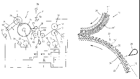
As shown in fig. 1, reference number 10 indicates a film of plastic, paper
CA 02567974 2006-11-23
WO 2005/123555 PCT/EP2005/005368
8
or other material, which is unwound from a roll, not shown, to be embossed and
rolled up or wound onto a spindle 25, to form a coreless or soft-core roll 11.
The film 10, which can be of any type, for example unrolled from large-
sized rolls, or directly from a production line, is made to advance along an
em-
bossing path at a first feeding speed S1 by means of a feeding device 12 com-
prising a drawing roller 13 and a pressure roller 14.
The drawing roller 13 is operatively connected to a first electric motor 15
provided with a first signal generator 16, consisting for example of an incre-
mental encoder.
Subsequently to the first drawing unit 12, the film 10 is deviated by two
idle guide rollers 17 and 18, spaced apart in the longitudinal direction of
the film,
to provide an upwardly extending loop 19; the loop 19 is freely maintained sus-
pended in the air, in a floating condition, for example by an air get
generated by
a nozzle 20, parallely extending on a side of a grooved drum 22 forming part
of
an embossing device, or by several nozzles aligned in the cross direction of
the
film 10, or in any other way, for example by vacuum from above.
Subsequently the guide rollers 17 and 18, the film 10 is advanced towards
an embossing and film wrapping device 21 comprising a longitudinally grooved
drum 22 on which the film 10 is shaped into a corrugated form, by embossing
cross ridges and grooves in absence of any tension or longitudinal stress,
before
being wound onto the roll 11; the roll 11 is made to rotate, by friction, by
the
aforesaid grooved drum 22.
The rotational speed of the drum 22 is controlled by a second electric mo-
tor 23 to draw the film 10 with a second linear speed S2 lower than and corre-
CA 02567974 2006-11-23
WO 2005/123555 PCT/EP2005/005368
9
lated to the speed S1 of the feeding device 12, for the reasons explained
further
on. Therefore the second electric motor 23 for controlling the grooved drum 22
is
connected to a second signal generator 24 for example consisting of an incre-
mental encoder.
The roll 11 of film material is wound onto an idle spindle 25, for example
of expandable type, rotatably supported by a rocking arm 26, which can tilted
around an axle 26' operated by a third electric motor 27, to constantly urge
the
roll 11 against the grooved drum 22 in such a way as to constantly control the
diameter and the compaction degree of the roll 11 during winding.
Means are provided for controlling the feed rate of the film 10 to the em-
bossing device 21; as shown in fig. 1, the feed rate control means comprises a
loop sensing device 28, for example an optical sensor for continuously
detecting
the position of and/or the depth of the loop 19, while reference number 29
indi-
cates a nozzle or group of nozzles which extends transversally, substantially
across the entire width of the film 10, parallel with and at a short space
from the
grooved outer surface of the drum 22; the nozzle 29 is connected to a pressure
air source 30 by means of a pneumatic control valve 31, of proportional type
to
change and adjust the air pressure and/or the air flow rate, consequently to
vary
the air jet which urges the film 10 against to and into the grooves of the
emboss-
ing drum 22; the above will be explained in greater detail further on, with
refer-
ence to figures 2, 3 and 4 of the accompanying drawings.
Lastly, still with reference to fig. 1, reference number 32 indicates an elec-
tronic control unit, which is programmable according to an appropriate
algorithm
for controlling the driving motors 15, 23, 27 and the pneumatic valve 31 for
ad-
CA 02567974 2006-11-23
WO 2005/123555 PCT/EP2005/005368
justing the pressure of the pressurised air, in relation to control signals
received
from the two encoders 16 and 24, and from the sensor 28.
In particular, the electronic unit 32 controls and regulates the various op-
erative parameters of the apparatus, such as the speed S1 for advancing the
5 film 10 by the feeding device 12, and the speed S2 at embossing drum 22 for
winding up the film 10 onto the roll 11 by means of the same embossing device
21; the speed S2 of the film in the embossing device must always be lower than
the feeding speed S1 in the feeding device 12 so that the film 10 is made to
ad-
vance and wound onto the roll 11 under non-stressed conditions; the electronic
io control unit 32, by means of the signals received from the sensor 28 also
con-
trols the depth or the position of the loop 19 of film, the air jet from the
nozzle 29,
as well as the force or pressure exerted by the roll 11 against the grooved
drum
22, all as indicated in fig. 1.
As mentioned initially, the film 10 may be wound up into a coreless or
soft-core roll 11 maintaining an undulated configuration, in a condition
substan-
tially free from stress, so as to trap air along the cross folds or
corrugations be-
tween adjacent turns of the roll.
A similar configuration of the film 10 while it is being wound onto the roll
11, proves to be advantageous for various reasons: firstly, by winding up the
film
into a corrugated form, in the absence of longitudinal stresses, makes it
possible
to achieve a regular formation of structurally more resistant coreless or soft-
core
rolls, capable of absorbing any longitudinal contraction of the film, thus
reducing
the risk of implosion of the same roll in that any contraction is absorbed by
the
cross corrugations or folds in the film.
CA 02567974 2006-11-23
WO 2005/123555 PCT/EP2005/005368
11
By embossing cross folds in the film wound into rolls, having open side
ends, makes it also possible to achieve a partial discharge of the air trapped
be-
tween the turns, both during the winding, and in the event of any shrinkage oc-
curring in the film material, thereby obviating the onset of any stresses
within the
roll itself and a possible implosion of the inside turns; in this way it is
possible to
produce rolls substantially free from irregularities and defects.
This can be achieved by the use of the special grooved roller 22 and the
nozzle 29 for generating a jet of pressurised air, as is illustrated in
greater detail
in the figures from 2 to 4, in which the same reference numbers of fig. 1 have
io been used to indicate similar or equivalent parts.
As shown in figures 2 and 3, the grooved drum 22 can consist, for exam-
ple, of a steel cylinder 33 provided with a rubber sheathing 34 or other
suitable
elastically yielding material, having a plurality of grooves 35 which extend
longi-
tudinally to the drum, parallel to its rotational axis.
The profile of the grooves 35 and the ridges 36 can be of any shape; for
example as shown in fig. 3 the grooves 35, likely the ridges 36, have a
rounded
bottom 35' and a depth "d" ranging from 1 to 5 mm, and a pitch "p" between ad-
jacent grooves 35 ranging from 2 to 8 mm according to the type and thickness
of
the film 10 to be wound up.
The winding of coreless or soft-core rolls in conformity with the method
according to this invention, takes place in the following way: the film 10 is
fed
continuously, by means of the feeding device 12, at a first linear speed S1
corre-
sponding to the tangential speed of the roller 13 under the control of the
elec-
tronic control unit 32. Simultaneously, the film 10 is drawn by the embossing
and
CA 02567974 2006-11-23
WO 2005/123555 PCT/EP2005/005368
12
wrapping device 21 at a second linear speed S2 lower than the preceding speed
S1, coinciding with the tangential speed of the grooved drum 22, and then
wound onto the roll 11 being supported by the idle spindle 25.
The grooved drum 22 is also controlled by the electronic unit 32 in such a
way as to maintain the difference between the two speeds S1-S2 at a constant
pre-established value, depending on embossing conditions and the quantity of
film material in excess which has to be wound onto the roll 11 due to the
number
and depth of the embossed corrugations or folds, compared to the theoretical
quantity of un-embossed film to be wound for each complete rotation of the
1o grooved drum 22; in other words, the difference S1-S2 between the speed S1
and the speed S2, must be such as to supply an additional quantity of film
mate-
rial 10 to compensate for the formation of the embossed folds or corrugations,
at
each rotation of the grooved drum 22.
The above is made possible by the fact that the electronic unit 32 con-
trols, by an electronic gearing connection, the motors 15 and 23 which actuate
the feeding device 12 and the embossing device 21.
Between the two devices 12 and 21, the film 10 is made to advance in a
non-tout condition substantially free from stress; in this connection, as
shown in
fig. 1, in a position between the feeding and embossing devices, in correspon-
2o dence with the two guide rollers 17 and 18, the film 10 is deviated to form
an U-
shaped loop 19 which is freely suspended in the air, in a floating condition,
for
example by means of a weak air jet directed upwards, generated by the nozzle
20, or in any other suitable way, for example by vacuum from above; the
position
or depth of the loop 19 of film is continuously detected by a sensor 28, to
com-
CA 02567974 2006-11-23
WO 2005/123555 PCT/EP2005/005368
13
pensate for any variations in the feeding speed S1 and embossing or winding
speed S2 of the film 10.
Subsequently to the guide rollers 17, 18 and the loop 19, the film 10 is
made to advance drawn by the grooved drum 22, in correspondence with which
a second nozzle 29 is arranged. The nozzle 29 generates an air blade along the
entire length of the grooved drum; by controlling the feed rate of the film 10
and
the pressure of the air jet by' means of a proportional valve 31, it is thus
possible
to make the film 10 penetrate into the individual grooves 35 of the drum 22 by
a
desired quantity under controlled conditions, thereby creating a succession of
1o cross folds or corrugations 10' extending over the entire width of the film
10.
The film 10, in a corrugated condition, drawn or pulled by the drum 22 is
then wound up, without any tension, onto the roll 11 maintained in rotation by
the
grooved drum itself, as shown in the enlarged detail of fig. 5.
The method for winding up and forming rolls 11 of embossed film materi-
als, takes place under the control of the electronic unit 32 conformed for
such
purpose. In fact, the electronic unit 32, with its outlets Ml and M2 controls
the
motors 16 and 23 of the feeding and embossing devices 12 and 21, and conse-
quently the feeding speed S1 and the winding speed S2 of the film 10. With its
outlet Vp it controls the solenoid valve 31, and consequently the air jet and
the
2o depth of penetration of the film 10 into the grooves 35 in the grooved drum
22
which determines the depth of the corrugations and the quantity of film wound
in
excess onto the roll 11 at each turn; as mentioned initially, this helps to
make the
structure of the roll 11 more stable, in the production either of coreless and
soft-
core rolls.
CA 02567974 2006-11-23
WO 2005/123555 PCT/EP2005/005368
14
Moreover, the electronic unit 32 with its outlet F controls, in a programmed
mode, the motor 27 for actuating the support arm 26 for the roll 11, and conse-
quently the pressure exerted by the same roll 11 against the grooved drum 22,
thereby making it possible to control the diameter and the compactness of the
roll 11, during winding of the film 10, in relation to data programmed into
the con-
trol unit 32.
Lastly, at its inlets El, E2 and S the control unit 32 receives control sig-
nals from the encoders 16, 24 and from the sensor 28; therefore, in the event
the sensor 28 is detecting a displacement of the loop 19 of the film, due for
ex-
1o ample to a variation in the winding speed S2, or for any other cause, the
control
unit 32 actuates the motors 15 and/or 23 to restore the balance in the system,
in
relation to operative parameters preset into the control unit 32.
In order to produce coreless or soft-core rolls which are structurally more
stable, as well as free from defects, according to a further feature of the
inven-
tion it has been found advantageous to wound a number of initial turns of the
roll
in a compact mode; this may be done at the beginning of the winding step, for
example by pressing the roll 11 against the grooved drum 22, by means of the
arm 26, maintaining under tension the film during the winding, and then
slightly
releasing the pressure, continuing the winding of the film in the corrugated
form
2o as described previously; this makes it possible to form an initial support
core by
the more compacted turns on which to wind the subsequent turns of the roll,
thereby reducing or eliminating any risk of implosion.
The above has been shown by way of example in fig. 4 where reference
11' indicates the first group of compacted turns wound without corrugations,
CA 02567974 2006-11-23
WO 2005/123555 PCT/EP2005/005368
while reference 11" indicates the subsequent corrugated turns, during the wind-
ing up step of the roll.
In this connection, the control unit 32 is programmed in such a way that at
the beginning of the winding of each roll, the support arm 26 is moved in the
di-
5 rection of the arrow indicated in fig. 5, pressing the roll 11 more against
the
grooved drum 22, during the winding up of the first 20-50 turns of film,
thereupon
continuing the winding of the embossed film while constantly maintaining the
lat-
ter in a non-taut condition.
At the completion of a roll, the latter is withdrawn after having disengaged
1o it from the spindle, for example, by reducing the diameter of the
expandable
spindle 25, or in any other suitable way.
Fig. 5 of the drawings shows a second embodiment of the apparatus,
which differs from the previous one in respect to the system for forming the
loop
19, and for maintaining the film 10 in an unstressed condition; therefore in
fig. 5
15 the same reference numbers have been used to indicate parts similar or
equiva-
lent to those of fig. 1.
The embodiment of fig. 5 differs from that of fig. 1 in that the loop 19 is
now directed with the bottom facing downwards, and is formed immediately
downstream of the feeding device 12, between the latter and the first guide
roller
17; moreover, the same nozzle 20 also is now facing downwards, while the sen-
sor 28 has been positioned beneath the loop 19.
The apparatus of fig. 5 operates exactly in the same way as the apparatus
of fig. 1.
A third embodiment is shown in fig. 6 and 7 of the drawings, in which the
CA 02567974 2006-11-23
WO 2005/123555 PCT/EP2005/005368
16
same reference numbers of the previous figures have been used for correspond-
ing parts.
The embodiment of fig. 6 and 7 differs from the embodiments of figs. 1
and 5 in that the loop 19, downstream the feeding device, is provided by a
pneumatically actuate devices 43 comprising a movable and adjustably supports
idle roller 45.
As shown, the idle roller 45 is supported by an arm 46, which may pivot
around an axis 47 coaxial to the shaft of the roll 13.
The pivotal movement of the arm 46 is adjustably performed by an actua-
1o tor, for example by an air pressure actuated cylinder 48 hinged to the arm
46
and connected to an air pressure source 50 by a control valve 49 controlled by
the outlet Vs of the control unit 33.
Position sensing means for the idle roller 45, such as linen encoder 51 are
provided to control the position and/or the depth of the loop 16 as per
previous
cases.
An additional feature of the method and apparatus according to the inven-
tion is again shown in fig. 6; as shown in this figure, an intermediate film-
drawing
device, comprising a drawing or pulling roll 40, has been added upstream and
close to the embossing drum 22, to better control the feed rate of the film
10.
The drawing roll 40 is connected to a motor 41 connected to a signal gen-
erator 42, both connected to the outlet M3 and inlet E3 of the control unit
32.
The apparatus of fig. 6 again operates as the apparatus of the previous
embodiments, with the additional feature of more precisely control the feed
rate
of the film to the embossing roll and the final diameter of the same roll 11
by ad-
CA 02567974 2006-11-23
WO 2005/123555 PCT/EP2005/005368
17
justing and controlling the embossing deep of the film in the grooves, of the
em-
bossing drum 22.
From what has been described and shown in the accompanying drawings,
it is evident that a method and an apparatus for producing coreless and soft-
core
rolls, of film materials have been provided, by means of which the aforemen-
tioned scopes and advantages are achieved; therefore other modifications or
variations may be made to the method for producing the rolls, and to the
appara-
tus itself, in relation to specific requirements, without thereby departing
from the
scope of the claims.