Sélection de la langue

Search

Sommaire du brevet 2568001 

Énoncé de désistement de responsabilité concernant l'information provenant de tiers

Une partie des informations de ce site Web a été fournie par des sources externes. Le gouvernement du Canada n'assume aucune responsabilité concernant la précision, l'actualité ou la fiabilité des informations fournies par les sources externes. Les utilisateurs qui désirent employer cette information devraient consulter directement la source des informations. Le contenu fourni par les sources externes n'est pas assujetti aux exigences sur les langues officielles, la protection des renseignements personnels et l'accessibilité.

Disponibilité de l'Abrégé et des Revendications

L'apparition de différences dans le texte et l'image des Revendications et de l'Abrégé dépend du moment auquel le document est publié. Les textes des Revendications et de l'Abrégé sont affichés :

  • lorsque la demande peut être examinée par le public;
  • lorsque le brevet est émis (délivrance).
(12) Brevet: (11) CA 2568001
(54) Titre français: SYSTEME SOUS-MARIN DE COMMUNICATIONS ROBUSTES
(54) Titre anglais: ROBUST UNDERWATER COMMUNICATION SYSTEM
Statut: Accordé et délivré
Données bibliographiques
(51) Classification internationale des brevets (CIB):
  • H04B 11/00 (2006.01)
  • H04L 01/00 (2006.01)
  • H04L 27/00 (2006.01)
(72) Inventeurs :
  • PEARCE, CHRISTOPHER DUDLEY (Royaume-Uni)
  • SMITH, RICHARD JAMES DUDLEY (Royaume-Uni)
(73) Titulaires :
  • SONARDYNE INTERNATIONAL LTD.
(71) Demandeurs :
  • SONARDYNE INTERNATIONAL LTD. (Royaume-Uni)
(74) Agent: SMART & BIGGAR LP
(74) Co-agent:
(45) Délivré: 2014-01-28
(86) Date de dépôt PCT: 2005-05-03
(87) Mise à la disponibilité du public: 2005-12-22
Requête d'examen: 2010-04-30
Licence disponible: S.O.
Cédé au domaine public: S.O.
(25) Langue des documents déposés: Anglais

Traité de coopération en matière de brevets (PCT): Oui
(86) Numéro de la demande PCT: PCT/GB2005/001668
(87) Numéro de publication internationale PCT: GB2005001668
(85) Entrée nationale: 2006-11-24

(30) Données de priorité de la demande:
Numéro de la demande Pays / territoire Date
0413137.1 (Royaume-Uni) 2004-06-12

Abrégés

Abrégé français

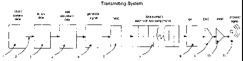
L'invention concerne un système sous-marin de communications robustes permettant d'établir une communication entre un émetteur de signaux acoustiques et un récepteur de signaux acoustiques distant. Les données sont portées par une pluralité de symboles, chacun d'eux comprenant deux composants dont l'un comprend un code binaire distinct et l'autre appartient au caractère du symbole comme un tout. Le caractère des symboles successifs est modifié par l'intermédiaire d'une séquence de répétition prédéterminée et continue d'étapes distinctes, chacune d'elles n'apparaissant qu'une fois dans la séquence. Le récepteur de signaux fonctionne de manière synchrone avec l'émetteur de signaux, comprend un agencement de corrélateur sensible à la fois au code binaire et au caractère des signaux reçus afin d'effectuer une démodulation et comprend une pluralité de sorties, une pour chaque symbole, de sorte que lorsqu'un symbole est détecté, un signal sur la sortie à laquelle il correspond prédomine. Un organe de détection d'amplitude sensible aux sorties provenant l'agencement de corrélateur permet de fournir un signal de sortie correspondant aux données transmises.


Abrégé anglais


A robust underwater communication system, for communication between an
acoustic signal transmitter and a remotely positioned acoustic signal
receiver, wherein transmitted data is carried by a plurality of symbols each
having two components one of which comprises a distinctive bit code and the
other of which appertains to the character of the symbol as a whole wherein
the character of successive symbols is stepped through a predetermined
continuously repeating sequence of distinctive steps each of which occurs once
in the sequence, the signal receiver being operated synchronously with the
signal transmitter and comprising a correlator arrangement responsive both to
the bit code and to the character of received signals for effecting
demodulation and having a plurality of outputs one for each symbol, so that as
each symbol is detected a signal on the output to which it corresponds
predominates and amplitude detector means responsive to the outputs from the
correlator arrangement for providing an output signal corresponding to the
data transmitted.

Revendications

Note : Les revendications sont présentées dans la langue officielle dans laquelle elles ont été soumises.


9
CLAIMS
1. An underwater communication system comprising:
an acoustic signal transmitter; and
a remotely positioned acoustic signal receiver; wherein
the acoustic signal transmitter is arranged to transmit data
encoded as a plurality of symbols, each symbol of the plurality of
symbols having two components one of which comprises a distinctive
bit code and the other of which appertains to the frequency of a
carrier signal on which the symbol is transmitted; wherein
the frequency of the carrier signal of successive symbols is
arranged to be stepped through a predetermined continuously
repeating sequence of distinctive steps each of which occurs once in
the sequence; and
the signal receiver is arranged to be operated synchronously
with the signal transmitter; and further comprising:
a correlator unit arranged to be responsive both to the bit code
and to the frequency of the carrier signal of received signals for
effecting demodulation and having a plurality of outputs one for each
symbol, so that as each symbol is detected a signal on the output to
which it corresponds predominates; and
an amplitude detector arranged to be responsive to the outputs
from the correlator unit for providing an output signal corresponding
to the data transmitted.
2. An underwater communication system as claimed in claim 1,
wherein the sequence used comprises sufficient step changes for
enough time to have elapsed to allow all significant multi-path
components to decay to insignificance before it is repeated.

10
3. An underwater communication system as claimed in claim 1 or
claim 2, wherein the bit code which comprises the first component of
each symbol is arranged to be transmitted using phase shift keying
(PSK) and the frequency of the carrier signal of each symbol is
arranged to be changed from symbol to symbol by hopping the
carrier frequency on which the symbol is transmitted through a
predetermined continuously repeating sequence of frequencies.
4. An underwater communication system as claimed in claim 3,
wherein the transmitter comprises PSK modulator arranged to
effectively hop the frequency of the carrier signal carrying the signal
thus modulated, the receiver comprising frequency/phase detector
means for detecting both of the two components of the received
signals which detector is arranged to feed a correlator to which the
amplitude detector is responsive for providing output signals
corresponding to the data transmitted.
5. An underwater communication system as claimed in claim 4,
wherein the frequency/phase detector comprises a phase quadrature
detector.
6. An underwater communication system as claimed in any one of
Claims 1 to 5, wherein the correlator unit of the receiver is arranged
to employ optimal correlation processing of the signals and thus is
arranged to continuously generate replicas of all the possible signals
at each epoch in a bank of corrrelators, thereby to facilitate symbol
recognition based on a maximum likelihood detection principle.
7. An underwater communication system as claimed in any one of
Claims 1 to 6, wherein synchronisation is arranged to be achieved by

11
transmitting a wideband header signal at the start of each signal
sequence, the receiver being arranged to detect the wideband
header signal.
8. An underwater communication system as claimed in any one of
Claims 1 to 7, wherein a tail signal is arranged to be appended at the
end of each signal sequence.
9. An underwater communication system as claimed in claim 8,
wherein compensation for relative motion between the transmitter
and receiver is arranged to be effected in dependence on the relative
times of arrival of the head and the tail signals.
10. An underwater communication system as claimed in claim 8,
wherein relative motion compensation is arranged to be implemented
using time of arrival estimates of each symbol.
11. An underwater navigation system comprising the
communication system as claimed in any one of Claims 1 to 10.
12. An underwater positioning system comprising the
communication system as claimed in any of claims 1 to 10.
13. An underwater communication system comprising:
an acoustic signal transmitter; and
a remotely positioned acoustic signal receiver, wherein
data is encoded prior to transmission as a plurality of symbols
each having two components one of which comprises a distinctive bit
code and the other of which appertains to the character of the symbol
as a whole, the character of successive symbols being stepped

12
through a predetermined continuously repeating sequence of
distinctive steps each of which occurs once in the sequence by
hopping the carrier frequency on which the symbols are to be
transmitted through a predetermined continuously repeating
sequence of frequencies;
the distinctive bit code comprises the first component of each
symbol is transmitted by the transmitter using phase shift keying
(PSK); and
the signal receiver is operated synchronously with the signal
transmitter and comprises a correlator unit responsive both to the bit
code and to the character of received signals for effecting
demodulation and having a plurality of outputs one for each symbol,
so that as each symbol is detected a signal on the output to which it
corresponds predominates; and
an amplitude detector responsive to the outputs from the
correlator means for providing an output signal corresponding to the
data transmitted; wherein
the bit code of each symbol and the character of successive symbols
are changed in accordance with the predetermined sequence and
synchronising operation of the transmitter and receiver.

Description

Note : Les descriptions sont présentées dans la langue officielle dans laquelle elles ont été soumises.


CA 02568001 2006-11-24
WO 2005/122446 PCT/GB2005/001668
1
Robust Underwater Communication System.
This invention relates to underwater communication systems.
More especially but not exclusively it relates to robust
underwater communication systems, which facilitate positioning
and/or navigation in or under water. Typically such systems are used
in the offshore oil and gas industry for positioning various kinds of
object such as work vessels on the surface, and vehicles or structures in
the water column or on the sea bed. In addition, these systems may
carry command and control signals or other data from object to object.
Such systems may also find application in the naval field for
communication with sub-sea vessels/vehicles.
The most practical means of distance measurement, bearing
measurement, velocity measurement and communicating underwater is
by using ultra-sound or acoustic signals. Modern systems are often
highly integrated with inertial / attitude sensors and above surface
radio navigation positioning systems such as the Global Positioning
System (GPS). However, in practice, the underwater part of these
systems uses acoustic signaling.
In these systems there are several, sometimes conflicting
requirements for data communication. For example in the case of a
command, control and navigation system requirement relatively small
volumes of data must be delivered reliably, securely and with
minimum latency in a wide range of conditions and in the case of a
sub-sea recording instrument large volumes of data, typically in file
structures, should be retrievable using a minimum of ship time.
It is generally recognised that high performance communication
underwater is more difficult than in equivalent systems using radio
signals. This is due to the presence of high acoustic noise levels in and

CA 02568001 2006-11-24
WO 2005/122446 PCT/GB2005/001668
2
around the working environment as well as other problems due to
aeration, multi-path effects, volume reverberation, and limited
frequency bandwidth, which may very well give rise to poor wanted
signal to noise power ratios. Additionally motion of the transmitter
with respect to the receiver may also give rise to problems.
Considering these problems in a, little more detail, multiple signal
paths (multi-path effects) result from the reflections of signals from the
water surface, from the seabed and from other underwater boundaries
such as a ship's hull for example. Also due to temperature variation
with depth, the sea may not be homogeneous but appear to have a
layered structure that.refracts sound and may also cause multi-path
effects. The overall effect may be that at any instant a received signal
comprises the sum of several different versions of the signal arriving in
several different paths.
In communication systems different signals represent different
symbols that in turn represent different data sequences and thus a
major problem with underwater communications is inter-symbol
interference. The problem can be avoided by using symbols with long
time duration but this limits the data rate, which is an important
performance parameter. Another technique is to use time or frequency
domain "equalisation" to order the data and thereby to remove a
significant amount of interference. Most known embodiments use a
pre-amble sequence of known data for training purposes which is
complex and requires a minimum time period to transfer any data
which makes the method more suitable for the transfer of large
volumes of data typically in file structures.
Complexity can however be something of a problem in
underwater systems because underwater navigation beacons and most

CA 02568001 2006-11-24
WO 2005/122446 PCT/GB2005/001668
3
other sub-sea instrumentation is battery powered, and there is a direct
roughly proportional relationship between system complexity and
energy consumed. Thus undue complexity is generally to be avoided to
reduce the time between battery changes.
Additionally the performance of a communications system
depends upon frequency bandwidth as well as wanted signal power to
noise ratio at the receiver. In water, sound absorption increases with
frequency and as a result any system with a practical range capability,
particularly in a noisy environment, has a limited bandwidth compared
with radio systems. Efficient use of bandwidth is thus another desirable
requirement.
In conventional narrowband systems, intra-symbol interference,
i.e. alternate constructive and destructive interference causes
fluctuations in signal amplitude and power. The effect is commonly
referred to as fading which may be mitigated by using wideband
signals.
It is an object of the present invention to provide an underwater
communication system wherein the foregoing problems are mitigated
at least in part thereby to provide a system which is not unduly
complex and yet capable of efficient operation in difficult working
conditions.
According to the present invention an underwater
communication system is provided, for communication between an
acoustic signal transmitter and a remotely positioned acoustic signal
receiver, wherein transmitted data is carried by a plurality of symbols
having two components one of which comprises a distinctive bit code
and the other of which appertains to the character of the symbol as a
whole wherein the character of successive symbols is changed through

CA 02568001 2006-11-24
WO 2005/122446 PCT/GB2005/001668
4
a predetermined continuously repeating sequence of distinctive steps,
each of which occurs once in the sequence, the signal receiver being
operated synchronously with the signal transmitter and comprising
correlator means responsive both to the bit code and to the character
of received signals and having an output, one for each symbol, so that
when a symbol is received, a signal on the output to which it
corresponds predominates and amplitude detector means responsive to
the outputs from the correlators for providing an output signal
corresponding to the data transmitted.
By changing not only the bit code of each symbol but also the
character of successive symbols in accordance with a predetermined
sequence and synchronising operation of the transmitter and receiver,
detection of a wanted signal is facilitated in the presence of unwanted
spurious signals and noise which might otherwise interfere with
reception.
In particular the effect of spurious signals due to multi-path
effects are substantially obviated because such signals will have died
away by the time the sequence is repeated and preferably the sequence
used comprises several step changes so that it does not repeat until
sufficient time has elapsed for any significant multi-path component of
its previous occurrence to decay substantially to insignificance.
The bit code which comprises the first component of each symbol
may be transmitted using phase shift keying (PSK) and the character of
each symbol may be changed from symbol to symbol by hopping the
carrier frequency on which it is transmitted through the said
predetermined continuously repeating stepped sequence.
The transmitter may comprise PSK modulator means, and means
for hopping the frequency carrier carrying the signal thus modulated,

CA 02568001 2006-11-24
WO 2005/122446 PCT/GB2005/001668
the receiver comprising frequency/phase detector means for detecting
both components of the received signal which detector means is
arranged to feed a correlator to which the amplitude detector is
responsive for providing an output signal corresponding to the data
transmitted.
The frequency/phase detector means may comprise a phase
quadrature detector.
The correlator of the receiver preferably employs optimal
correlation processing of the signals and thus continuously generates
replicas of all the possible signals at each epoch, i.e. signal period, in a
bank of correlators, whereby signal /symbol decisions using the
maximum likelihood principle are thereby facilitated.
Ideally the signals should have sufficient bandwidth to resolve
paths in time as required for each application in view.
Synchronisation may be achieved using a wideband header
signal.
A similar tail signal may be appended at the end of each
sequence.
For short data packets and modest data rates, compensation for
relative motion between the transmitter and receiver is not a necessity
but for higher rates compensation may be achieved using time of
arrival estimates of the head and the tail signal and comparing the time
difference with the known "as transmitted" time difference, the
comparison for compensation purposes being applied after signal
detection.
Alternatively the relative motion compensation may be
implemented using time of arrival estimates of each symbol and a

CA 02568001 2006-11-24
WO 2005/122446 PCT/GB2005/001668
6
Kalman filter method for optimal estimation of the time scale
difference between the transmitter and the receiver.
It will be appreciated by those skilled in the art that systems
according to the invention substantially resolve the problem of
providing secure, reliable command and control links suitable for use
in a wide range of operating conditions. Also compared with known
systems, greater data rates are achievable with increased speed of
operation of the whole system and in view of its simplicity, a relatively
small power consumption implementation is possible, which in battery-
powered instruments/apparatus is a desirable feature.
In particular this invention facilitates the transmission of modest
sized data packets with a minimum of delay, with minimum impact on
the navigation system, through a multi-path environment to a receiver
located on a noisy work vessel or platform.
One embodiment of the invention will now be described by way
of example only with reference to the accompanying drawings in
which;
Figure 1, is a schematic block circuit diagram of an acoustic signal
transmitter and,
Figure 2, is a schematic block circuit diagram of an acoustic signal
receiver for use with the transmitter of Figure 1.
Referring now to Figurel, an acoustic signal transmitter
comprises a data store 1, for data which is converted to a
corresponding binary signal format in a binary converter 2, 3. In order
to facilitate error correction at the receiver, which may be affected in
any known manner, appropriate additional redundant data is added in
a code generator 4, which is re-ordered to a format suitable for
synthesis in a signal processor S. The signal thus processed is further

CA 02568001 2006-11-24
WO 2005/122446 PCT/GB2005/001668
7
modified by the addition of header bits in an adder 6, which facilitates
recognition in the receiver of the start of a sequence and
synchronization of the transmitter and the receiver. Data comprises
encoding n bits at a time using 2 =m symbols in a repeating sequence,
which data bits are PSK modulated onto a carrier which is frequency
hopped through the sequence in a modulator 7, utilising orthogonal
carrier frequencies to produce a pseudo random sequence. A tail is
appended in a processor 8, and the resultant signal is fed via a digital
to analogue converter 9, and a power amplifier 10, the output of which
is matched, to an acoustic signal transducer for transmission of the
acoustic signal through the water to a receiver as shown in Figure 2.
It will be appreciated that the carriers do not themselves carry
any information but they are a means of mitigating multi-path signals
at the receiver.
Turning now to Figure 2, at the receiver, the analogue acoustic
signal is received by a transducer 12, amplified in an amplifier 13, and
converted to sampled digital format at a suitable rate in an A to D
Converter 14. The digital signal thereby produced is mixed down to a
convenient intermediate frequency in a phase quadrature detector,
which comprises mixers 15a and 15b fed with signals in phase
quadrature generated by a local oscillator 15c. Phase quadrature
related signals from the mixers 15a, 15b, are decimated using filter 16
to another suitable rate. The decimated signal is fed to a bank of
complex correlators comprising matched filters 17.
For each epoch in the signal sequence, the filters are matched to
the head signal, the 211 symbols or tail as appropriate. A symbol present
decision is made in an amplitude detector 18, which is made on a

CA 02568001 2006-11-24
WO 2005/122446 PCT/GB2005/001668
8
maximum likelihood basis in dependence upon all outputs from the
filters 17, the largest output being selected.
A resultant decoded data sequence is passed to an error
detection/correction module 19 wherein the redundant data is used to
detect transmission errors and if possible to correct them. The original
data and an error report is formatted in a processor 20 and delivered
therefrom in an appropriate format.
Various modifications may be made to the exemplary
embodiment hereinbefore described without departing from the scope
of the invention and for example the nature of two components may be
defined using other techniques as will be well known to those skilled in
the art. To give just one example, the first component comprising the
data may comprise pulse code modulation and the second component
defining the repeating sequence may comprise phase modulation. It
will be appreciated that other suitable combinations.of modulation for
the *two components are also possible.

Dessin représentatif
Une figure unique qui représente un dessin illustrant l'invention.
États administratifs

2024-08-01 : Dans le cadre de la transition vers les Brevets de nouvelle génération (BNG), la base de données sur les brevets canadiens (BDBC) contient désormais un Historique d'événement plus détaillé, qui reproduit le Journal des événements de notre nouvelle solution interne.

Veuillez noter que les événements débutant par « Inactive : » se réfèrent à des événements qui ne sont plus utilisés dans notre nouvelle solution interne.

Pour une meilleure compréhension de l'état de la demande ou brevet qui figure sur cette page, la rubrique Mise en garde , et les descriptions de Brevet , Historique d'événement , Taxes périodiques et Historique des paiements devraient être consultées.

Historique d'événement

Description Date
Représentant commun nommé 2019-10-30
Accordé par délivrance 2014-01-28
Inactive : Page couverture publiée 2014-01-27
Inactive : Taxe finale reçue 2013-11-08
Préoctroi 2013-11-08
Un avis d'acceptation est envoyé 2013-05-10
Lettre envoyée 2013-05-10
Un avis d'acceptation est envoyé 2013-05-10
Inactive : Approuvée aux fins d'acceptation (AFA) 2013-05-07
Modification reçue - modification volontaire 2012-11-26
Inactive : Dem. de l'examinateur par.30(2) Règles 2012-06-08
Lettre envoyée 2010-05-13
Exigences pour une requête d'examen - jugée conforme 2010-04-30
Toutes les exigences pour l'examen - jugée conforme 2010-04-30
Requête d'examen reçue 2010-04-30
Inactive : Déclaration des droits - Formalités 2007-08-02
Inactive : Lettre de courtoisie - Preuve 2007-02-06
Inactive : Page couverture publiée 2007-02-01
Inactive : Notice - Entrée phase nat. - Pas de RE 2007-01-29
Demande reçue - PCT 2006-12-19
Exigences pour l'entrée dans la phase nationale - jugée conforme 2006-11-24
Demande publiée (accessible au public) 2005-12-22

Historique d'abandonnement

Il n'y a pas d'historique d'abandonnement

Taxes périodiques

Le dernier paiement a été reçu le 2013-04-25

Avis : Si le paiement en totalité n'a pas été reçu au plus tard à la date indiquée, une taxe supplémentaire peut être imposée, soit une des taxes suivantes :

  • taxe de rétablissement ;
  • taxe pour paiement en souffrance ; ou
  • taxe additionnelle pour le renversement d'une péremption réputée.

Les taxes sur les brevets sont ajustées au 1er janvier de chaque année. Les montants ci-dessus sont les montants actuels s'ils sont reçus au plus tard le 31 décembre de l'année en cours.
Veuillez vous référer à la page web des taxes sur les brevets de l'OPIC pour voir tous les montants actuels des taxes.

Titulaires au dossier

Les titulaires actuels et antérieures au dossier sont affichés en ordre alphabétique.

Titulaires actuels au dossier
SONARDYNE INTERNATIONAL LTD.
Titulaires antérieures au dossier
CHRISTOPHER DUDLEY PEARCE
RICHARD JAMES DUDLEY SMITH
Les propriétaires antérieurs qui ne figurent pas dans la liste des « Propriétaires au dossier » apparaîtront dans d'autres documents au dossier.
Documents

Pour visionner les fichiers sélectionnés, entrer le code reCAPTCHA :


Pour visualiser une image, cliquer sur un lien dans la colonne description du document. Pour télécharger l'image (les images), cliquer l'une ou plusieurs cases à cocher dans la première colonne et ensuite cliquer sur le bouton "Télécharger sélection en format PDF (archive Zip)" ou le bouton "Télécharger sélection (en un fichier PDF fusionné)".

Liste des documents de brevet publiés et non publiés sur la BDBC .

Si vous avez des difficultés à accéder au contenu, veuillez communiquer avec le Centre de services à la clientèle au 1-866-997-1936, ou envoyer un courriel au Centre de service à la clientèle de l'OPIC.


Description du
Document 
Date
(aaaa-mm-jj) 
Nombre de pages   Taille de l'image (Ko) 
Description 2006-11-23 8 374
Dessins 2006-11-23 2 21
Dessin représentatif 2006-11-23 1 8
Revendications 2006-11-23 3 109
Abrégé 2006-11-23 1 69
Revendications 2012-11-25 4 145
Dessin représentatif 2013-12-26 1 6
Paiement de taxe périodique 2024-04-25 2 63
Rappel de taxe de maintien due 2007-01-28 1 111
Avis d'entree dans la phase nationale 2007-01-28 1 205
Rappel - requête d'examen 2010-01-04 1 125
Accusé de réception de la requête d'examen 2010-05-12 1 177
Avis du commissaire - Demande jugée acceptable 2013-05-09 1 163
Taxes 2012-05-02 1 157
PCT 2006-11-23 3 97
Correspondance 2007-01-28 1 27
Correspondance 2007-08-01 4 77
Taxes 2010-04-29 1 201
Correspondance 2013-11-07 1 46
Taxes 2015-04-29 1 26
Paiement de taxe périodique 2017-04-23 1 26
Paiement de taxe périodique 2019-04-16 1 26
Paiement de taxe périodique 2020-04-26 1 27