Note : Les descriptions sont présentées dans la langue officielle dans laquelle elles ont été soumises.
CA 02568704 2006-11-23
APPARATUS FOR ELEVATING TIRE INTERIOR CONTENTS OF A
REFRIGERATION UNIT OR THE LIKE
This invention relates to improvements in household refrigeration units, and
more
particularly to household refrigerators and freezers of the top-opening type.
BACKGROUND
A major fault of conventional side-opening freezer and refrigerator units
(side-opening
units) is that when one of these units is opened, cold air within the unit,
being heavier
than the warm air of the surrounding room, flows out through the lower portion
of the
unit's doorway and is replaced by warm air which flows into the unit through
the upper
portion of the doorway. This necessitates a re-cooling of most of the interior
volume of
the unit every time the unit's door is opened. This fault is largely remedied
by top-
opening freezer and refrigerator units (top-opening units). When one of these
units is
opened, the cold air within the unit, being heavier than the air of the
surrounding room,
stays inside of the unit's compartment. The only increase in temperature is
caused by the
momentary contact between the air within the unit and the outside air. This
increase is
negligible when compared to the temperature increase caused by briefly opening
a side-
opening unit.
The disadvantage of a top-opening unit lies in the inaccessibility of goods
stored in the
bottom of the unit's well or compartment. When a top-opening unit is utilized
to capacity,
2
CA 02568704 2006-11-23
boxes and packages are piled on top of each other. To access an article at the
bottom of a
full unit, overlying articles must first be removed by hand, a distinctly
uncomfortable and
inconvenient exercise. Accessing an article at the bottom of a top-opening
unit also
reduces the efficiency of the unit, as the unit must be kept open during the
hand sorting of
its contents.
Prior art attempts to solve the accessibility problem have included the use of
baskets
which hang from the top of the freezer into the interior. The baskets are
removed to
access the lower items. Typically the number of baskets is limited so that the
baskets can
be manually slid to one side or the other to access the area under the basket
without
actually removing the basket.
It is also known to provide vertical dividers to divide the freezer interior
into a plurality
of vertical compartments. Thus a much smaller number of upper items need to be
removed to access items at the bottom of the compartment, since the dividers
prevent
adjacent items from falling into the space that is being opened to access the
bottom.
A problem with removing upper items or whole baskets of items to access lower
items is
that occasionally the item or basket is forgotten in a location outside the
freezer where it
2D was placed while accessing lower items. Such items can spoil quickly if the
error is not
discovered in a short time.
SUMMARY OF THE INVENTION
3
CA 02568704 2006-11-23
It is an object of the present application to provide a top-opening
refrigeration unit that
overcomes probiems in the prior art. The present invention provides improved
accessibility in an energy efficient top-opening refrigeration unit such as is
used for
freezing or cooling contents.
In a fust embodiment the present invention provides a storage insert for a top
opening
storage unit. The insert comprises an outer frame shaped to fit within the top-
opening
unit, and an inner frame movably mounted to the outer frame for up and down
movement
relative to the outer frame. At least one substantially horizontal shelf is
mounted on the
inner frame, and a lifting assembly is operatively connected between the inner
and outer
frames to selectively raise and lower the inner frame relative to the outer
frame.
In a secand embodiment the present invention provides a top opening
refrigeration unit
comprising a main body having a substantially horizontally oriented open top,
and a door
pivotally attached along a top edge of the main body and movable from a closed
position
covering the open top, to a raised open position. An inner f.fame is movably
mounted
inside the main body such that the inner frame can move relative to the main
body from a
lowered position inside the main body, to a raised position at least partiaily
above the
open top of the main body. At least one substantially horizontal shelf is
mounted on the
inner frame, and a lifting assembly is operatively connected between the inner
frame and
the main body to selectivety raise and lower the inner frame.
4
CA 02568704 2006-11-23
In a third embodiment the present invention provides a method of providing
access to an
interior of a top opening storage unit. The method comprises mounting at least
one
substantially horizontally oriented shelf within the interior of the storage
unit and
operatively connecting the at least one shelf to a selectively operable
lifting mechanism
for vertically raising and lowering the at least one shelf relative to the
unit's interior.
The present invention thus provides a simple apparatus for mechanically
lifting the
interior contents of a top-opening unit, thus maicing the contents of the unit
easily
accessible. The lifting apparatus can be configured to be easily installed in
ezisting top-
opening units, or integrated into a storage unit such as a freezer or the like
during
manufacture. It is contemplated that the lifting apparatus will allow
efficient use of a
significantly larger proportion of the available volume of the freezer
interior compared to
the prior art, and combined with drawer type shelves or rotating shelves the
convenience
and capacity can be increased still further.
MCRIPTION OF THE DRAWINGS
While the invention is claimed in the concluding portions hereof, preferred
embodiments
are provided in the accompanying detailed description which may be best
understood in
conjunction with the accompanying diagrams where like parts in each of the
several
diagrams are labeled with like numbers, and where:
5
CA 02568704 2006-11-23
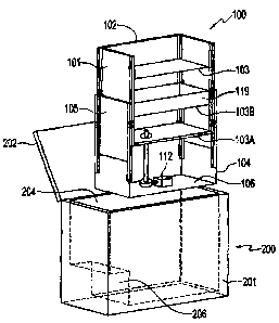
Fig. 1 is a schematic perspective view of an embodiment of the insert of the
present invention and a top-opening unit where the insert may be installed;
Fig. 2 is a schematic cut-away perspective view of the threaded rod lift
assembly
used in the embodiment of Fig. 1;
Fig. 3 is a schematie top view of an alternate embodiment of the insert of the
present invention using a cable and pulley lift assembly and installed in a
freezer;
Fig. 4 is a schematic front view of the embodiment of Fig. 3;
Fig. 5 is a schematic illustration of a lifting mechanism provided by
pneumatic
cylinders powered by pressurized refrigerant fluid from a refrigeration unit.
DETAILED DESCRIP'rION OF THE ILLUSTRATED $MB DII1~',NTS
As ahown in Fig. 1 an apparatus in the nature of a storage insest 100
according to an
embodiment of the present invention comprises an inner frame 102 having walls
101 and
shelves 103, and an outer frame 104 having walls 105 and a lloor 106. The
walls 101,
105 and floor 106 provide the required structural integrity to the inner and
otrter frames
102, 104. Sufficient structural integrity could also be provided by a frame
work of braces
or the like, as will be recognized by persons skilled in the art.
6
CA 02568704 2006-11-23
The outer frame 104 is shaped to fit within the storage unit such as the
illustrated top-
opening freezer unit 200 with a hinged door 202 covering the open top of a
storage
compartment 204 inside the freezer. Similar mfrigeration units are known that
only cool
the contents instead of freezing same, and the storage insert 100 could be
configured
readily for use in these units as well.. The inner frame 102 is movably
mounted to the
outer frame 104 for up and down movement relative to the outer frame 104. In
the
embodiment of Fig. 1 the inner frame 102 is essentially a box that fits in a
sliding
relationship inside a slightly bigger box that is the outer frame 104.
Stability for inner
frame 102 when elevated is also provided by the sliding proximity of inner
frame walls
101 to outer frame walls 105. A plurality of horizontal shelves 103 are
mounted on the
inner frame 102.
When inner frame 104 of insert 100 is in its lowest position, the insert fits
inside storage
compartmerit 204 and door 202 can be opened and closed without interference.
in the
iIIustrated embodiment, the insert 100 is shaped to fit beside the freezer's
compressor
housing 206 in the bottom of the compartment 204.
The illustrated shelves 103 can be simple flat surfaces or drawers could be
provided
instead to both increase the capacity by utilizing more of the available
volume of the
freezer interior, and further facilitate easy access to items on the rear
portion of the
shelves. Horizontal shelf 103B is laterally slidable with respect to the inner
frame 102,
and includes side panels 119 forming a drawer that can slide in and out to
provide
improved access to the items at the rear of the shelf 103B, and also increase
the capacity
7
CA 02568704 2006-11-23
of the shelf 103B by ensuring that items placed on the shelf remain on the
shelf.
Similarly it is contemplated that a lazy-susan type rotating shelf might be
utilized
advantageously as wel}.
As seen in Fig. 2 a lifting assembly 110 is attached to the floor 106 of outer
fran-e 104.
TEie lifting assembly 110 is operatively connected between the inner and outer
frames
102, 104 to selectively raise and lower the inner frame 102 relative to the
outer frame
104. The lifting assembly 110 includes a motor 112, and a drive mechanism
actuatable
by the motor and configured such that when the motor 112 rotates in a first
direction the
inner frame 102 moves upward relative to the outer frame 104, and such that
when the
motor 112 rotates in an opposite second direction the inner frame 102 moves
downward
relative to the outer frame 104.
In the illustrated embodiment the motor 112 is operatively connected to a
drive
mechanism comprising a rotating screw actuator 114, which turns a threaded rod
116.
The threaded rod 116 extends substantially vertically into a threaded aperture
defined in a
substantially horizontal base support member E07 that is attashe.d to the
bottorrf shelf
103A. Rotation of the rod 116 in one direction raises the inner frame 102 and
rotation in
the other direction lowers the inner frarne 102.
When a user activates motor 112 using for example an externally mounted
switch, motor
112 rotates screw actuator 114 which rotates threaded rod 116. The cotacing
rod 116
causes the threaded base support 107 to move upward.lnner frame 102, fixedly
attached
8
CA 02568704 2006-11-23
to lower shelf 103A and thus to threaded base support 107, moves in concert.
Thus, inner
frame 102 and shelves 103 and any containers or items on the shelves of the
inner frame
move upwardly for easy access.
To lower inner frame 102, motor 112 is activated to rotate in the opposite
direction, and
thus rotate the rod 116 in the opposite direction until inner frame 102 is
fuily lowered into
the freezer.
Figs. 3 and 4 illustrate an altemate storage insert 300 comprising a network
of pulleys
316 and cables 318 connected to the inner frame 302 and the outer frame 304. A
cable
drum 314 is rotatably attached to a bottom portion of the outer frame 304
about a
substantially vertical axis DA. The cables 318 are connected to the drum 314
and the
dnun 314 is connected to be rotated by the motor 312 and the drive mechanism
310 to
raise and lower the inner frame 304.
In the alternate insert 300, instead of taking the form of a small box inside
a larger box as
in the embodiment of Figs. 1 and 2, the outer frame 304 comprises four upright
frame
members 324 configured to be located in a cent.ral portion of the freezer 400,
and the
inner fratne 302 extends out to the ends of the freezer 400 to just fit inside
the freezer
compartment. When moving up and down the inner frame 302 is maintained in
position
by its close proximity to the ends of the freezer compartment. The bottom of
the inner
frame 302 is configured to fit above the freezer's compressor housing 406 in
the bottom
of the compartment 404. While the inner frame 302 is illustrated without any
shelves
9
CA 02568704 2006-11-23
mounted thereon for clarity of illustration, those skilled in the art will
recognize that
shelving can be readily added in a variety of ways.
The storage insert 300 comprises upper and lower front right, upper and lower
front left,
upper and lower rear right, and upper and lower rear left pulleys 316 attached
to the
upper and lower ends of the upright frame members 324. A front right cable
318A is
wrapped on the drum 314 and passes from the drum 314 to the lower front right
pulley
316LFR, then up to the upper front right pulley 3I6UFR, then down to the inner
fi-ame
302. Cables 318B, 318C, and 318D are siniilarly wrapped on the cable drum 314
and
pass through pulleys 316 on the other upright frame members 324 to the inner
frame 302
such tbat the inner frame is supported in a horizontal position as
illustrated. As the motor
312 rotates the drum 314 the cables wind onto the drum 314 to raise the inner
frame 302,
and when the motor 312 rotates in the opposite direction, the weight of the
inner frame
302 draws the cables 318 off the drum 314 and the inner frame moves down.
The insert of the invention is adaptable to existing freezers and like storage
units by
properly configuring the insert to fit the unit desired. The insert can also
be incorporated
during manufacture. The lift assembly, pulleys, drive mechanism, and the like
can be
mounted directly as required on the main body of the freezer unit, instead of
on an outer
frame that would be inserted into the freezer conmpartment.
It will be appreciated by the person skilled in the art that the lifting
assembly can be
hydraulically or pneumatically actuated. Other lifting mechanisms could be
used, for
CA 02568704 2006-11-23
example meshing rack and pinion gears or pneumatic lift cylinders could be
located at the
corners of the freezer. For example Fig. 5 illustrates a lifting mechanism
comprising a
plurality of pneumatic cylinders 425. One cylinder 425 is located at each
corner of the
freezer, and the cylinders 425 are actuated by pressurized refrigerant fluid
from the
freezer refrigeration system. The refrigeration system includes a compressor
427
operative to draw refrigerant fluid from the low pressure side of the system
LP, compress
the fluid, and direct same into the high pressure side of the system HP.
Pressurized refrigerant fluid from the high pressure side HP is connected to a
control
valve 429, and through the valve 429 to the cylinders 425 which are slaved so
as to move
up and down together to raise and lower the inner frame and shelves. The
return line
from the Iast slaved cylinder 425 is connected to the control valve 429 and
through same
to the low pressure side of the system LP. Reservoirs 431 are added to both
the high
pressure side HP and low pressure side I.P of the system to provide sufficient
capacity to
operate the system satisfactorily using a conventional freezer compressor. The
pressurized refrigerant system of the freezer or like refiigeration unit could
also similarly
be connected to power a motor in a lifting mechanism.
The foregoing is considered as illustrative only of the principles of the
invention.
Further, since numerous changes and modifications will readily occur to those
skilled in
the art, it is not desired to limit the invention to the exact construction
and operation
shown and described, and accordingly, all such suitable changes or
modifications in
11
CA 02568704 2006-11-23
structure or operation which may be resorted to are intended to fall within
the scope of
the claimed invention.
12