Note : Les descriptions sont présentées dans la langue officielle dans laquelle elles ont été soumises.
CA 02569792 2006-12-06
WO 2006/007137 PCT/US2005/017650
TITLE OF THE INVENTION
Catheter Assembly
FIELD OF THE INVENTION
The present invention relates to catheters having at least a guide wire
lumen and a delivery lumen.
BACKGROUND OF THE INVENTION
A variety of different therapies can be delivered within the human body
by catheter devices. Therapeutic devices such as dilatation balloons, stents,
and embolic filters, and therapeutic agents such as drugs and radiation
sources, may be positioned at or near the distal end of the catheter for
delivery
to a desired site within the body.
The prior art discloses numerous examples of intravascular catheters.
Such catheters have found particular utility for procedures such as
angioplasty
and stent deployment. Of particular interest recently is improving catheters
for
use in percutaneous transluminal coronary angioplasty (PTCA) procedures. In
typical PTCA procedures a guiding catheter is advanced in the patient's
vasculature until the distal tip of the guiding catheter is seated in the
ostium of
a desired coronary artery. A guide wire is first advanced out of the distal
end of
the guiding catheter into the patient's coronary artery until the distal end
of the
guide wire crosses a lesion to be dilated. A dilatation catheter, having an
inflatable balloon on the distal portion thereof, is advanced into the
patient's
coronary artery over the previously introduced guidewire until the balloon of
the
dilatation catheter is properly positioned across the lesion. Once properly
positioned, the dilatation balloon is inflated with inflation fluid one or
more times
to a predetermined size at relatively high pressures so that the stenosis is
compressed against the arterial wall and the wall expanded to open up the
vascular passageway. Generally, the inflated diameter of the balloon is
approximately the same diameter as the native diameter of the body lumen
being dilated so as to complete the dilatation but not overexpand the artery
wall. After the balloon is finally deflated, blood flow resumes through the
dilated artery and the dilatation catheter and the guidewire can be removed
therefrom.
1
CA 02569792 2006-12-06
WO 2006/007137 PCT/US2005/017650
In such angioplasty procedures, there may be restenosis of the artery
(i.e. reformation of the arterial blockage) which necessitates either another
angioplasty procedure, or some other method of repairing or strengthening the
dilated area. To reduce the restenosis rate of angioplasty alone and to
strengthen the dilated area, physicians now normally implant an intravascular
prosthesis, generally called a stent, inside the artery at the site of the
lesion.
Stents may also be used to repair vessels having an intimal flap or dissection
or to generally strengthen a weakened section of a vessel or to maintain its
patency. Stents are usually delivered to a desired location within a coronary
artery in a contracted state on a balloon of a catheter which is similar in
many
respects to a balloon angioplasty catheter, and expanded within the patient's
artery to a larger diameter by expansion of the balloon. The balloon is
deflated
to remove the catheter and the stent left in place within the artery at the
site of
the dilated lesion.
With regard to coronary catheters, two main types of catheter designs,
over-the-wire (OTW) and rapid-exchange (RX), dominate these applications.
Each of these designs has its advantages and disadvantages. OTW catheters
track over their entire length on a guidewire, which allows them to follow the
wire easily and allows the direct transmission of longitudinal force over the
guidewire. Additionally, these catheters allow for guidewires to be exchanged
once the catheter has been advanced into position, which may be desirable
when different guidewire attributes (e.g., tip curvature or radiopaque
markers)
are needed. However, these systems require the use of a long guidewire (e.g.,
300cm in length) and cannot be effectively operated by one person.
RX catheters typically use shorter guidewires (e.g., 180 cm in length)
which allow the catheter to be operated by a single physician. The physician
is
able to hold the guide catheter and guidewire with one hand while using
his/her
other hand to advance or retract the catheter along the guidewire. However,
because the entire length of the RX catheter does not slide over the
guidewire,
the direct transmission of longitudinal force along the path of the guidewire
may
be compromised, and wire exchange can not be performed once the proximal
catheter guidewire port is advanced into the patient. Another problem with the
design of RX catheters is that, compared to traditional OTW catheters, it
results in catheters which have inferior pushability and also tend to buckle
and/or kink - especially at or near the proximal (or rapid-exchange) guide
wire
exit port.
More recently introduced coronary catheters are hybrids of the OTW
and RX catheters, sometimes referred to as "convertible" catheters. For
2
CA 02569792 2008-07-28
WO 2006/007137 PCT/US2005/017650
example, US Patents 5,334,147 and 5,380,283 to Johnson teach the
construction of a balloon catheter having a proximal portion that includes an
aperture through the wall of the catheter into the guidewire lumen. The
aperture is covered by a frangible wall (e.g., a thin-walled tube sealed to
the
catheter body in a position to cover the aperture portion). The frangible wall
may be punctured by a guidewire, allowing the guidewire to exit the catheter
guidewire lumen via the aperture. Thus, providing both rapid-exchange and
over-the-wire capabilities.
US Patent 5,472,425 to Teirstein describes a catheter having a
guidewire lumen covered by a rupturable membrane that extends along
substantially the entire length of the catheter, whereby the membrane may be
intentionally punctured at any desired location by the guidewire. Thus,
providing both rapid-exchange and over-the-wire capabilities. The use and
general construction of the catheter are related, although no materials or
specific constructions for the rupturable mernbrane are taught.
Commonly owned and co-pending US Patent Publication No. 2004/0193139,
filed on March 28, 2003, to Armstrong et al describes a unique convertible
catheter that comprises a guidewire lumen having a thin covering that is
easily
punctured to form a guidewire exit port at virtually any desired point along
the
catheter. The thin covering may be integral with the catheter shaft, or may be
a separate component that covers only the portion of the catheter shaft
immediately adjacent the outer portion of the guidewire lumen, or may be a
thin
tubular construct that surrounds the entire catheter shaft. In one disclosed
embodiment the thin covering is made from a thin tape of porous expanded
polytetrafluoroethylene (ePTFE) helically wrapped about the exterior of a
catheter shaft. The wrapping can be accomplished, for example, in two
opposing directions parallel to the length of the catheter shaft, resulting in
a
bias-ply construction. This thin covering offers good transparency and is
easily
punctured (e.g., by the end of a guidewire) and yet is resistant to tearing at
the
puncture site. Other disclosed materials for the thin covering include, for
example, polyethylene terephthalate (PET), polyethylene, polypropylene,
polyamide, etc. Porous polymers, optionally provided with a thin, non-porous
coating, may be advantageously used because of their excellent flexibility.
Most preferred are tapes made from thin ePTFE film that has been provided
with a porous or non-porous coating of a thermoplastic such as a thermoplastic
fluoropolymer, preferably fluorinated ethylene propylene (FEP). Exemplary
ePTFE films can be made as taught by US Patents 3,953,566 and 4,187,390 to
Gore. More preferred are ePTFE films made as taught be US Patent
3
CA 02569792 2006-12-06
WO 2006/007137 PCT/US2005/017650
5,476,589 to Bacino. The construction of thin, helically-wrapped tubes from
ePTFE films and thermoplastic-coated ePTFE films, and the method of
providing the coating onto the ePTFE films, are taught, for example, by US
Patent 6,159,565 to Campbell et al. The guidewire lumen can be in the form of
a slot made into the catheter shaft, with the slot provided with the thin
covering.
Preferably, the slot extends for most or even all of the length of the
catheter.
The slot can be covered with a thin tubular covering that coaxially encloses
the
entire catheter shaft or alternatively a strip of thin tape-like covering
material
that covers the slot and is adhered to the surface of the catheter shaft
immediately adjacent both sides of the slot. A multiplicity of pre-formed
openings may be provided through the thin covering if desired. Also, the slot
covering material may take the form of a braid or winding of filaments. This
braid or winding of filaments may optionally be covered with a thin polymeric
tube except for the filaments immediately over the top of the slot which
preferably remain exposed and allow for passage of the end of a guidewire
through any interstice between adjacent filaments.
A further problem with conventional balloon catheters for intravascular
procedures, such as angioplasty and stent delivery, is such catheters
frequently have stiff proximal sections to facilitate advancement of the
catheter
within the patient's body lumen and relatively flexible distal shaft sections
to
facilitate passage through tortuous anatomy such as distal coronary and
neurological arteries without damage to the luminal wall. Typically, there is
an
intermediate shaft section or junction between the relatively stiff proximal
shaft
section and the relatively flexible distal shaft section that provides a
transition
between the proximal shaft section and the distal shaft section.
A variety of proposed solutions to the problems of providing catheters
with rapid-exchange capabilities, good pushability, smooth flexibility
transition
from proximal end to distal end, and good resistance to buckling and/or
kinking
(especially at the proximal (or rapid-exchange) guide wire exit port) have
been
attempted. However, the search continues for a catheter that overcomes all of
these problems.
SUMMARY OF THE INVENTION
Catheters having at least two lumens are disclosed. The catheter
includes a proximal section and a distal section. The proximal section and
distal section may be joined together at a joint, or the sections may be a
single
piece formed by, for example, extruding plastic material. The proximal section
4
CA 02569792 2006-12-06
WO 2006/007137 PCT/US2005/017650
includes at least a delivery lumen extending from the proximal end (or near
the
proximal end) to the distal end thereof. Located in at least a portion of the
proximal section delivery lumen is reinforcing tubular member, which is
positioned to structurally support the wall of the proximal section delivery
lumen
of the catheter. The reinforcing tubular member is constructed or configured
to
transition from being relatively rigid at a proximal point to being relatively
more
flexible at a distal point. In an aspect of the invention the reinforcing
tubular
member transitions from being relatively rigid at substantially its proximal
end
to being relatively flexible at its distal end. In an aspect of the invention,
the
reinforcing tubular member may extend from the proximal end of the proximal
section to (or close to) the distal end.
The proximal section of the catheter also includes a guidewire receiving
lumen. The guidewire receiving lumen may extend from the distal end of the
proximal section to a point distal of the proximal end, or the guidewire
receiving
lumen may extend from the distal end of the proximal section to the proximal
end thereof. The guidewire receiving lumen includes at least one proximal
guidewire exit port located proximally from the distal end of the proximal
section. The reinforcing tubular member extends to a point distal of the
proximal guidewire exit port, and has an outer diameter equal to about the
inner diameter of the delivery lumen for at least a portion of the reinforcing
tubular member that extends distal to the proximal guidewire exit port. By
extending the reinforcing tubular member distal to the guidewire exit port in
this
manner, the catheter will have improved columnar strength (i.e. it will resist
buckling while being advanced, or pushed, toward the desired treatment site)
and pushability. The guidewire receiving lumen and the delivery lumen should
be in a parallel relationship. This allows for the reinforcing tubular member
to
extend distal to the proximal guidewire exit port, while maintaining an outer
diameter equal to about the inner diameter of the delivery lumen to provide
structural support about the circumference of the lumen distal to the proximal
guidewire exit port.
The distal section of the catheter includes at least a guidewire receiving
lumen and a delivery lumen. In an aspect of the invention, the guidewire
receiving lumen extends from the proximal end of the distal section to the
distal
end of the distal section. The guidewire receiving lumen may also extend from
the proximal end of the distal section to a point proximal of the distal end.
The
delivery lumen extends from the proximal end of the distal section to the
distal
end thereof, or to a point proximal of the distal end. The distal section
delivery
lumen is in fluid communication with the proximal section delivery lumen and
5
CA 02569792 2006-12-06
WO 2006/007137 PCT/US2005/017650
the distal section guide wire receiving lumen is in fluid communication with
the
proximal section guide wire receiving lumen.
DESCRIPTION OF THE DRAWINGS
The operation of the present invention should become apparent from
the following description when considered in conjunction with the
accompanying drawings, in which:
Figure 1 is a longitudinal view of a catheter according to the invention.
Figure 2 is a cross-section of the catheter of Figure 1, taken along lines
2-2 in Figure 1.
Figure 3 is a cross-section of the catheter of Figure 1, taken along lines
3-3 in Figure 1.
Figure 4 is a cross-section of the catheter of Figure 1, taken along lines
4-4 in Figure 1.
Figure 5 is a longitudinal cross-section of a portion of a catheter
according to the invention.
Figure 6 is a longitudinal view of a catheter according to the invention.
Figure 7 is a cross-section of the catheter of Figure 6, taken along lines
7-7 in Figure 6.
Figure 8 is a cross-section of the catheter of Figure 6, taken along lines
8-8 in Figure 6.
Figure 9 is a longitudinal view of a catheter according to the invention.
Figure 10 is a cross-section of the catheter of Figure 9, taken along
lines 10-10 in Figure 9.
Figure 11 is a cross-section of the catheter of Figure 9, taken along
lines 11-11 in Figure 9.
DETAILED DESCRIPTION OF THE INVENTION
The invention may best be understood with reference to the Figures
wherein certain preferred embodiments are set forth in detail.
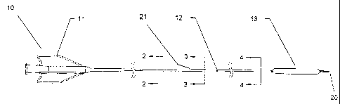
Turning to Figure 1 there is shown a rapid-exchange type balloon
catheter 10. Typically located on the proximal end of such a catheter is hub
assembly 11. As can be seen catheter 10 includes a proximal section and a
distal section in this case joined in abutting relationship at joint 12. The
proximal section and distal section can be joined in any suitable manner, such
as adhesively joined, fused, welded, etc. In an aspect of the invention the
6
CA 02569792 2006-12-06
WO 2006/007137 PCT/US2005/017650
proximal and distal sections are butt welded, glued, etc. together so as to
form
a smooth joint without one section overlapping the other, and without a
transition piece, such as a hollow tube, fitted over each piece. As shown in
Figure 2, proximal section includes an outer wall material 14 (such as a
plastic
material, or other suitable material) and reinforcing tubular member 15
supporting the outer wall 14. The proximal section also includes delivery
lumen
16 extending from the proximal end to the distal end of the proximal section.
Close to its distal end, proximal section also includes guidewire
receiving lumen 17 in parallel relationship with delivery lumen 16, as shown
in
Figure 3. Guidewire receiving lumen 17 extends distally from proximal
guidewire exit port 21 to the distal end of the proximal section. Guidewire
receiving lumen 17 and delivery lumen 16 remain parallel from proximal
guidewire exit port 21 to the distal end of the proximal section. In an aspect
of
the invention reinforcing tubular member 15 extends from the proximal end,
past proximal guidewire exit port 21, to the distal end of the proximal
section.
Reinforcing tubular member 15 can continuously increase in flexibility from
its
proximal end to its distal end. Reinforcing tubular member 15 has an outer
diameter equal to about the inner diameter of the delivery lumen 16 for at
least
a portion of the length of the reinforcing tubular member 15 that extends
distal
to the proximal guidewire exit port 21. In an aspect of the invention
reinforcing
tubular member 15 has an outer diameter equal to about the inner diameter of
the delivery lumen 16 over the entire length of the reinforcing tubular member
15.
As shown in Figure 4, the distal section includes guidewire receiving
lumen 17, defined by tubular member 19, and delivery lumen 16 defined by the
annular space between tubular member 18 and tubular member 19. Guidewire
receiving lumen 17 extends from the proximal end of the distal section through
balloon 13 to the distal end of the distal section, terminating at distal
guidewire
exit port 20. The delivery lumen 16 extends from the proximal end of the
distal
section to the proximal end of balloon 13. The delivery lumen 16 is in fluid
communication with the interior of balloon 13, so that inflation fluid can be
delivered to inflate the balloon 13. Balloon 13 can be sealed or otherwise
joined to the distal end of tubular member 18 and to a point near the distal
end
of tubular member 19 in any suitable manner, as is known to the skilled
artisan.
As shown in Figure 5, in an aspect of the invention guidewire receiving
lumen 17 and delivery lumen 16 can be in parallel relationship at the proximal
end of the distal section and then transition from being parallel to being
coaxial
as each lumen extends toward the distal end of the distal section. Moreover,
7
CA 02569792 2006-12-06
WO 2006/007137 PCT/US2005/017650
reinforcing tubular member 15 has an outer diameter equal to about the inner
diameter of the delivery lumen 16 and extends distally past proximal guidewire
exit port 21, contacting the inner wall around the circumference of the
delivery
lumen 16.
Typically, the catheter shown in Figure 1 will have an overall length of
about 145 to 150 cm (including the hub assembly). The proximal section
typically measures about 115 to 125 cm in length. The distal section typically
measures about 20 to 30 cm in length. The proximal guidewire exit port is
desirably located about 24 to 34 cm from the distal tip of the catheter. Of
course, the proximal guidewire port can be located closer to, or further from,
the distal tip if desired, including guidewire exit ports less than about 10
cm
from the distal tip of the catheter. Unlike prior art rapid-exchange
catheters,
catheters according to the invention can be produced where there is no
significant difference in deliverability based on the location of the proximal
guidewire exit port. The performance of the catheter is dominated by the
properties of the reinforcing tubular member, and the location of the proximal
guidewire exit port does not then cause a defect in the mechanical structure
of
the device.
Typical lumen dimensions for a coronary application would be 0.018"
nominal ID for the guidewire lumen and an 0.023" ID for the delivery lumen,
with wall thicknesses of 0.003" minimum. Typical materials would include
Nylon or Pebax of various grades or durometers. A reinforcing tubular member
of 304 SS could then have an OD of 0.022" and an ID of 0.016", allowing it to
fit in the ID of the delivery lumen. The reinforcing tubular member
flexibility can
be graduated by the addition of a spiral cut. A pitch in the cut of about 10
mm,
continuously decreased to a final pitch of about 1 mm, which can then be
extended for any desired length is particularly useful for devices intended
for
coronary applications. One knowledgeable in the art will notice that this
invention allows for great flexibility in design. A wide range of materials
and
sizes, including systems for 0.010", 0.014", 0.018", 0.033" or any other
guidewire size can be designed utilizing this invention.
Reinforcing tubular member 15 can be any suitable material. In an
aspect of the invention the reinforcing tubular member comprises a polymer
material. In a further aspect of the invention reinforcing tubular member
comprises a metal, such as a hypotube. Reinforcing tubular member 15 is
located within the delivery lumen of the proximal section and may extend from
a point near the proximal end of the proximal section to a point distal
thereto.
In an aspect of the invention the reinforcing tubular member extends
8
CA 02569792 2006-12-06
WO 2006/007137 PCT/US2005/017650
continuously from the proximal end to the distal end of the proximal section.
Moreover, the reinforcing tubular member 15 is configured or constructed or
otherwise altered so that the reinforcing tubular member becomes relatively
more flexible from a proximal point to a distal point thereon. In an aspect of
the
invention the reinforcing tubular member 15 transitions from rigid to
relatively
flexible in a continuous manner. In a further aspect of the invention the
reinforcing tubular member 15 transitions continuously from rigid to
relatively
more flexible from its proximal end to its distal end. Transition from rigid
to
relatively more flexible can be accomplished in any suitable manner. For
example, the distal end of the reinforcing tubular member could have a
reduced wall thickness, compared to the proximal end thereof. Moreover, the
tubular member could be spirally scored or cut (preferably cut completely
through the wall of the tube), with pitch being increased toward the distal
end of
the tubular member to result in a tubular member being more flexible at its
distal end, as compared to its proximal end. In an aspect of the invention,
the
tubular member can be cut along only a portion of the tubular member,
preferably near the distal end thereof. The tubular member can also be cut
along its entire length, with pitch being varied over a part of the tubular
member, or along the entire tubular member. The tubular member can be
configured so that the portion of the tubular member that extends from a point
proximal of the proximal guidewire exit port to a point distal to the proximal
guidewire exit port can have the same flexibility or it can increase in
flexibility
as it extends distal to the guidewire exit port. For coronary applications a
0.022
inch OD x 0.016 inch ID 304 stainless steel hypotube can be used. A final
pitch of about 1 mm can provide desirable flexibility. A starting pitch of
about
10 mm can provide a particularly smooth transition. Furthermore, tube
stiffness can be varied by combining two or more materials of varying
stiffness
and joining them together to form a tubular member of varying stiffness. Of
course, any combination of tube wall thickness, spirally scored or cut tubing,
pitch variations, and tube materials could be used to obtain a reinforcing
tubular member having increased flexibility gradient measured from a proximal
point to the distal point thereof. In an aspect of the invention the
reinforcing
tubular member may be adhered or attached to the inner wall of the delivery
lumen at any number of points along the length of the lumen. In an alternative
embodiment the reinforcing tubular member may be adhered or attached to the
inner wall of the delivery lumen at only one point (e.g., at the proximal end
of
the delivery lumen). In a further alternative embodiment, the reinforcing
tubular
member could be in the form of a wire, tubular braid which transitions from
9
CA 02569792 2006-12-06
WO 2006/007137 PCT/US2005/017650
relatively rigid to relatively flexible as it extends from a proximal point to
a distal
point. The wire, tubular braid could be embedded in the wall material that
forms the delivery lumen of the proximal section of the catheter. For example,
the wire, tubular braid could be imbedded in a suitable plastic tubular
material.
In an alternative embodiment, catheter 10 can be provided with a
guidewire receiving lumen that extends for the length (or most of the length)
of
the proximal section of the catheter. In this embodiment the proximal section
still includes delivery lumen 16 in parallel relationship with guidewire
receiving
lumen 17. However, guidewire receiving lumen 17 can be provided with at
least a second proximal guidewire exit port located proximally from the first
proximal guidewire exit port 21. In an aspect of this embodiment the at least
second proximal guidewire exit port is located at the proximal end of the
proximal section, thus resulting in the so-called "convertible catheter"
design.
In any event, reinforcing tubular member 15 still extends to a point distal to
the
first proximal guidewire exit port 21. In a further aspect the at least second
proximal guidewire exit port is located between the first guidewire exit port
21
and the proximal end of the proximal section of the catheter. In this aspect,
the
reinforcing tubular member 15 can extend distally past the most proximal
guidewire exit port, past the most distal guidewire exit port, or to the
distal end
of the proximal section of the catheter.
Turning to Figure 6 there is shown a catheter according to the invention
which is of the "convertible" type balloon catheter. The catheter includes
proximal section and distal section substantially as set forth in Figures 1-
4,
except that the guidewire receiving lumen 17 of the proximal section extends
substantially the length of the proximal section. Moreover, Y connector 30 is
provided at the proximal end of the catheter. In addition to first proximal
guidewire exit port 21, also provided are second 22 and third (not shown)
proximal guidewire exit ports. Second proximal guidewire exit port 22 is
located proximally from first proximal guidewire exit port 21 and third
proximal
guidewire exit port is located at the proximal end of the proximal section.
Thus,
it can be seen that the catheter of this embodiment can be used in the well
known "over-the-wire" mode by threading the guidewire through the distal
guidewire exit port 20, past the first and second proximal guidewire exit
ports,
and exit out the third proximal guidewire exit port. The catheter of this
embodiment can also be used in the "rapid-exchange" mode by threading the
guidewire through the distal guidewire exit port and through either the first
or
second proximal guidewire exit port.
CA 02569792 2008-07-28
WO 2006/007137 PCT/US2005/017650
Of course, it should be understood that further proximal guidewire exit
ports could be provided at any point along the guidewire receiving lumen
between the first proximal guidewire exit port 21 and the third proximal
guidewire exit port. This would allow the physician to choose between "over-
the-wire" mode and "rapid-exchange" mode wherein the "rapid-exchange"
feature could comprise many guidewire exit ports which may be utilized
depending upon various factors confronting the physician.
Reinforcing tubular member 15 has an outer diameter equal to about
the inner diameter of the delivery lumen 16 and extends from near the proximal
end of the proximal section to a point distal to the proximal guidewire exit
port
21.
A further variation of the "convertible catheter" embodiment is
exemplified in Figure 9. Figure 9 shows a catheter according to the teaching
of
commonly owned and copending US Patent Publication No. 2004/0193139, which
has been modified according to the present invention. Catheter 30 has
proximal and distal sections joined together in abutting relationship at joint
12.
Located at the proximal end of the catheter is Y connector 30. As can be seen
in Figure 10, proximal section includes parallel extending guidewire receiving
lumen 17 and delivery lumen 16. Guidewire receiving lumen 17 comprises a
longitudinally extending channel provided with thin cover material 31, in this
case coaxially wrapped about the proximal section of the catheter. Thin cover
material 31 can be any suitable material that: is capable of being pierced,
punctured, etc. to form a guidewire exit port therein. Thus, a proximal
guidewire
exit port can be made by the physician at virtually any point along the length
of
the proximal section of the catheter. Preferably the thin cover material 31 is
selected from those disclosed in commonly owned and copending US Patent
Application Publication No. 2004/0193139. Delivery lumen 16 has located
therein
reinforcing tubular member 15 which transitions from relatively rigid at a
proximal point to
relatively more flexible at a point distal thereto. Reinforcing tubular member
15
extends from near the proximal end of the proximal section to near the distal
tip
of the proximal section and has an outer diameter equal to about the inner
diameter of the delivery lumen 16 over its entire length and, thus, provides
structural support to the delivery lumen 16 essentially over the entire length
of
the proximal section. Distal section includes delivery lumen 16 extending from
the proximal end thereof into fluid communication with the interior of balloon
13,
which is mounted on the distal end of the catheter. As can be seen in Figure
11, at least a portion of delivery lumen 16 is defined by the annular space
between tubular members 18 and 19. Moreover, distal section also includes
11
CA 02569792 2006-12-06
WO 2006/007137 PCT/US2005/017650
guidewire receiving lumen 17 defined by tubular member 19 that extends from
the proximal end thereof to the distal end thereof, terminating at distal
guidewire exit port 20. Distal section delivery lumen 16, and distal section
guidewire receiving lumen 17 can be in parallel relationship at the proximal
end
of the distal section and transition to a coaxial relationship as the lumens
extend toward the distal end of the distal section. Any suitable means may be
used to join together the proximal and distal sections, or the catheter
assembly
may be a single extrusion as discussed above. As seen, the outer diameters of
the proximal section and the distal section are joined together in such a
manner
as to form a smooth outer profile transition from proximal section to distal
section.
Although balloon angioplasty catheters have been described in detail,
the invention also includes catheters other than balloon angioplasty
catheters.
For example, the balloon on the distal end of the catheter could be provided
with a stent, which can be delivered to a treatment site, as is well known in
the
art. Further, rather than using a balloon expandable stent, self-expanding
stents can be delivered using the catheter of the invention. Such a catheter
would include guidewire receiving lumen and delivery lumen, as discussed
above. However, rather than terminating at a proximal end of a balloon, the
delivery lumen could extend to the distal tip of the catheter. The self-
expanding
stent could be advanced through the delivery lumen to the treatment site and
the catheter withdrawn as the self-expanding stent is held stationary. The
stent
would then expand against the vessel wall as the catheter is withdrawn.
Furthermore, the delivery lumen could be used to deliver any number of
devices or treatments to a treatment site. For example, analytical devices
and/or other therapeutic devices could be advanced through the delivery lumen
to a treatment site. Moreover, ultra sound devices, fiber optics, stent
grafts,
embolic filters, radiopaque contrast material, medicines, etc. could be
delivered
via the delivery lumen of the catheter of the invention.
While particular embodiments of the present invention have been
illustrated and described herein, the present invention should not be limited
to
such illustrations and descriptions. It should be apparent that changes and
modifications may be incorporated and embodied as part of the present
invention within the scope of the following claims.
12