Note : Les descriptions sont présentées dans la langue officielle dans laquelle elles ont été soumises.
CA 02571120 2006-12-18
WO 2006/004995 PCT/US2005/023469
TITLE OF INVENTION
LOAD BALANCING IN A DISTRIBUTED TELECOMMUNICATIONS
PLATFORM
CROSS-REFERENCE TO RELATED APPLICATIONS
[00011 This application is a continuation-in-part of, United States Patent
Application
11/080,744 entitled DISTRIBUTED IP ARCHITECTURE FOR
TELECOMIVIUNICATIONS SYSTEM filed on March 15, 2005.
BACKGROUND OF THE INVENTION
[001121 The present invention relates to distributed IP systems and
telecommunication
systems and, more particularly, to a multi-functional telecominunications
system with
geographically dispersible components that interact over a distributed IP
architecture.
[00031 Over the past several decades, voice mail has continued to expand and
establish itself as a key element in the successful operations of most
businesses. The
typical voice mail system today can take on a variety of forms, including a
computer
card that can operate within a personal computer that is comiected to a
businesses
telephone system, or a computer card or component that is directly integrated
into the
businesses telephone system, or as a service provided by a telecommunications
company.
100041 The common ingredient to each of the voice mail systems available today
is
that the coinponents that make up the voice mail system must communicate with
each
other and thus, must be co-located. This can be a great disadvantage for
companies
that have geographically dispersed offices.
[0005] In today's global economy, even small business may have a need for
inultiple
offices for serving clients, interacting with vendors, or various other
reasons. The
advent of the Internet, email and video conferencing helps to allow such
dispersed
operations appear more seamless. However, a significant problem that still
exists for
dispersed offices is having a common telephonic system that operates as a
single, co-
located system but serves the needs of the various offices. Generally, each
office
purchases and maintains its own telephone system without any direct interface
between the telephone systems of the various offices and without any central
control.
This can be a costly endeavor in that duplicative hardware must be purchased
and
maintained at each site. In addition, the logistics of inter-office
communication such
as call transfers, voice mail retrieval etc. can be complex. Thus, there is a
need in the
1
CA 02571120 2006-12-18
WO 2006/004995 PCT/US2005/023469
art for a telecommunications system that allows seamless integration for
remotely
located offices.
[00061 In most distributed systems, a common problem that arises and must be
addressed is the distribution of processing between the various components. In
a
distributed system, a sub-set of the components can be overburdened with
processing
tasks while other components are idle or under utilized. Such a situation can
result in
tremendous and unnecessary decreases in the efficiency and throughput of the
system.
For instance, if the load can be distributed from overburdened conlponents to
under
utilized components, the system can more efficiently handle the processing
requirements. There are many such techniques that have been proposed and
implemented in an effort to balance the processing requirements in distributed
systems. However, such techniques are not adequate to meet the demands in the
distributed telecommunications platform described herein. For instance, wlien
one or
more components utilize JAVA 2 Enterprise Edition (J2EE) environment and JAVA
Server Pages (JSP), such as in creating dynamic VoiceXML pages, additional
problems can arise. In such a component, the JAVA engine allocates and
deallocates
memory wllile performing what is termed in the art as garbage collection. This
is a
key feature of Java which takes care of freeing dynamically allocated memory
that is
no longer referenced. Because the heap is garbage-collected, Java prograinmers
don't
have to explicitly free allocated memory. However, when the garbage collection
process commences, tremendous processing time can be required which directly
impacts the performance of the system. Thus, there is a need in the art for a
distributed system that allows for the reallocation of resources in a manner
that avoids
or alleviates the impact of a JAVA garbage collection process as well as other
processing requirements.
BRIEF SUMMARY OF THE INVENTION
[0007] This invention provides a technique for balancing the processing load
within a
distributed telecommunications system. In general, processing is distributed
at two
levels - the component level and the process level. At the component level, a
virtual
switch is employed to route service requests to one of a group of components
that are
configured to process the service request. The decision can be made
autonomously by
the virtual switch or entirely based on information provided by the component
or even
by a combination of botli. At the process level, each component establishes
multiple
2
CA 02571120 2006-12-18
WO 2006/004995 PCT/US2005/023469
instances of the serving process and then selects one instance to process the
service
requests. The component monitors the processing burden of the instance of the
process and if a degradation in performance is anticipated, the component
selects an
alternative instance of the serving process to handle subsequent requests.
[00081 In an exemplary embodiment of the present invention, the virtual switch
is
used to select between a group of application servers for handling
telecommunication
service requests. The application servers utilize a J2EE platform that
includes a
garbage collection process. If a single instance of the serving process is
used,
eventually the garbage collection process will require a high execution
priority and at
such a time, performance degradation would be experienced by users of the
telecommunications system. The multiple instances allow the garbage collection
process to operate off line without impacting the performance experienced by
the
users.
BRIEF DESCRIPTION OF THE SEVERAL VIEWS OF THE DRAWING
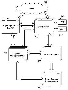
10009;1 Fig. 1 is a system diagrain illustrating the components and the
connectivity of
an exemplary next-generation communications platform in which various aspects
and
features of the present invention can be utilized.
[0010] Fig. 2 is a block diagram illustrating one potential configuration for
providing
load balancing in accordance with the present invention.
[0011] Fig. 3 is a flow diagram illustrating various aspects of the present
invention.
DETAILED DESCRIPTION OF THE INVENTION
l:(10'12'1 Fig. 1 is a system diagram illustrating the components and the
connectivity of
an exemplary next-generation communications platform in which various aspects
and
features of the present invention can be utilized. The illustrated system
includes a
distributed IP-based architecture for telecommunications equipment that, among
other
things, can provide telecommunication services such as voice mail, call
forwarding
and other telecommunication features. In the illustrated environment, the next-
generation communications platform 100 has a distributed IP architecture and
is
connected to the Public Switched Telephone Network (PSTN) 110. The
communications platform 100 is illustrated as including a signaling gateway
function
(SGF) 120, one or more media servers (MS) 130, one or more system management
units (S1VI[J) 140, one or more application servers (AS) 150 and one or more
central
3
CA 02571120 2006-12-18
WO 2006/004995 PCT/US2005/023469
data and message store (CDMS) 160. It should be understood that the
distribution of
functionality illustrated in the figures and described, although having novel
aspects in
itself, is not the only acceptable arrangement, and aspects of the present
invention
could be incorporated into a system that includes fewer or more components and
a
different arrangement of functionality among the components.
[0013] In general, the SGF 120 serves as the Signaling System 7 (SS7)
interface to
the PSTN 110 and allows one or more components or sub-systems to share the
same
point code (tliereby reducing the need for destination point codes (DPC) and
signaling
links for call-control. This makes the telephonic system appear as single
trunk group
in the network. The media server 130 terminates IP and/or circuit switched
traffic
from the PSTN via a multi-interface design and is responsible for trunking and
call
control. The application server module 150 generates dynamic VoiceXML pages
for
various applications and renders the pages through the media server 130 and
provides
an external interface via a web application server configuration. The SMU 140
is a
management portal that enables service providers to provision and maintain
subscriber accounts and manage network elements from a centralized web
interface.
The CDMS 160 stores voice messages, subscriber records, and manages specific
application functions including notification. Each of these sub-systems are
described
in more detail following.
10014] Each of the components in the next-generation communications platform
is
independently scalable and independently intercoimected onto an IP network.
Thus,
the components can be geographically distributed but still operate as a single
communications platforin as long as they can communicate with each other over
the
IP network. This is a significant advantage of the present invention that is
not
available in state-of-the-art communication systems.
Signaling Gateway Function (SGF)
[0{}:l5] The SGF 120 offers a consolidated signaling interface creating a
single virtual
SS7 signaling point for the next generation coinmunications platform. SS7
provides
the extra horsepower networks need, whether large or small. A SIGTRAN
interface
(IETF SS7 telephony signaling over IP) to the multi-function media server 130
as
well as IP Proxy functions are supported via the SGF 120. Consolidating SS7
into a
single component (in this case the SGF 120) of the next-generation
communications
platform provides the benefits of reduced point codes, cost efficiency in the
design of
the other components and easier maintenance.
4
CA 02571120 2006-12-18
WO 2006/004995 PCT/US2005/023469
[00.16] Each signaling point in the SS7 network is uniquely identified by a
numeric
point code. Point codes are carried in signaling messages exchanged between
signaling points to identify the source and destination of each message. Each
signaling point uses a routing table to select the appropriate signaling path
for each
message.
(.0017] There are three kinds of signaling points in the SS7 network: SSP
(Service
Switching Point), STP (Signal Transfer Point) and SCP (Service Control Point).
SSPs
are switches that originate, terminate or tandem calls. An SSP sends signaling
messages to other SSPs to setup, manage and release voice circuits required to
complete a call. An SSP may also send a query message to a centralized
database (an
SCP) to determine how to route a call (e.g., a toll-free 1-800/888 call in
North
America). An SCP sends a response to the originating SSP containing the
routing
number(s) associated with the dialed number. An alternate routing number may
be
used by the SSP if the primary nuinber is busy or the call is unanswered
within a
specified time. Actual call features vary from network to network and from
service to
service.
[00*1.8] Network traffic between signaling points may be routed via a packet
switch
called a Service Transfer Point or STP. An STP routes each incoming message to
an
outgoing signaling linlc based on routing information contained in the SS7
message.
Because it acts as a network hub, an STP provides improved utilization of the
SS7
network by eliminating the need for direct links between signaling points. An
STP
may perform global title translation, a procedure by which the destination
signaling
point is determined from digits present in the signaling message (e.g., the
dialed 800
number, calling card nuinber or mobile subscriber identification number).
[00191 An STP can also act as a "firewall" to screen SS7 messages exchanged
with
other networks. Because the SS7 network is critical to call processing, SCPs
and
STPs are usually deployed in mated pair configurations in separate pliysical
locations
to ensure network-wide service in the event of an isolated failure. Linlcs
between
signaling points are also provisioned in pairs. Traffic is shared across all
links in the
link set. If one of the links fails, the signaling traffic is rerouted over
another link in
the link set. The SS7 protocol provides both error correction and
retransmission
capabilities to allow continued service in the event of signaling point or
link failures.
]0020] The availability of point codes is typically limited. The consolidation
of
signaling links eases the pressure on these resources or eliminates the need
for
CA 02571120 2006-12-18
WO 2006/004995 PCT/US2005/023469
additional point codes altogether. Thus, the consolidated signaling interface
in the
SGF 120 provides immediate network simplification and cost savings. The SGF
120
presents the appearance of a single identity to the SS7 network via the single
"virtual"
point code of the messaging network a.nd recognizes and processes messages in
a
transparent manner. The SGF 120 can potentially reduce the maximu.in number of
point codes needed in some cases from 50 to only four.
[0023 ] From a networking perspective, the SGF 1201ooks like an STP to the
rest of
the network giving access to the various components of the next-generation
communications platform through the use of virtual point codes. In accordance
with
the distributed aspects of the present invention, multiple SGFs may be
incorporated
into the system. In this configuration, multiple paths to the various
components of the
next-generation cominunications platform are available.
[0022] Each SGF 120 includes virtual point codes that are used to access the
various
components in the commun.ications platform. Only one destination point code is
necessary for the entire communications platform. The SGFs communicate with
each
other to synchronize the virtual point codes for the media servers and other
components integrated into the communications platform. Thus, if one SGF
fails,
access to the communications platform is easily provided through another SGF.
[0023] This is significantly different and advantageous over each of the
components
in the next generation cominunications platform looking like synchronized SS7
stacks.
[0024] In an exemplary einbodiment, the SGF 120 server supports N+1 fail over
redundancy schemes and load sharing configurations and is built on an Intel
server. A
minimuin of two SGFs is recommended for load sharing and redundancy purposes
for
increased availability. As with all platform components, SNMP alarming,
logging,
and transaction detail records are generated. Features, advantages and
benefits of the
SGF include:
[0025] Allows multiple media servers to share signaling links and point codes
providing significant cost savings;
[0026] Provides concentrated SS7 signaling links;
1;0027] Can provide one trunk group across multiple multi-function media
servers;
(0028] SGF 120 requires less SS7 links resulting in reduced monthly connection
fees;
and
6
CA 02571120 2006-12-18
WO 2006/004995 PCT/US2005/023469
(0E129] The SGF 120 is a key component in the ability to implement an IP
distributed
architecture for the communications platform.
Media Server (MS)
1~10:341] The MS 130 terminates IP traffic from the SGF 120 and circuit-
switched
traffic from the PSTN 110. The MS 130 is responsible for call set up and
control
within the platform architecture. The MS 130 processes input from the user in
either
voice, DTMF format or other signaling schemes (much like a web client gathers
keyboard and mouse click input from a user). The MS 130 then presents the
content
back to the user in voice form (similar in principle to graphic and text
displayed back
to the user on a PC client). This client/server methodology is important in
the
platform architecture in that it enables rapid creation of new applications
and quick
utilization of content available on the World Wide Web.
[0031] The MS 130 preferably processes incoming calls via requests to the AS
150
using HTTP. A load balancer preferably directs traffic arriving at the multi-
function
MS 130 to one of a plurality of ASs 150. This functionality ensures that
traffic is
allocated evenly between active servers. The multi-fiuiction MS 130 works as
the
VoiceXML client on behalf of the end user in much the same manner as a client
like
Netscape works on behalf of an HTML user on a PC. A VoiceXML or Call Control
XML (CCXML) browser residing on a multi-function media server interprets the
VoiceXML documents for presentation to users.
[00321 VoiceXML is a standards-based scripting language for developing voice-
enabled software applications. This means that developers use and leverage Web-
based (HTML) development expertise in developing speech-based telephony
applications.
Application Server (AS)
[0033] The modular design of the next-generation communications platform has
the
added advantage that it is easy to deploy enhanced services, such as voice
dialing and
voice navigation, unified cominunications solutions, multimedia messaging
services,
and presence & availability management applications. Adding applications to
the
platform is accomplished via the addition of standard application servers 150
to the
common platform.
100341 Each application server 150 generates application docuinents (VoiceXML
pages) in response to requests from the media server 130 via the internal
Ethernet
network. The application server 150 leverages a web application infrastructure
to
7
CA 02571120 2006-12-18
WO 2006/004995 PCT/US2005/023469
interface with back-end data stores (message stores, user profile databases,
content
servers) to generate the VoiceXML based documents.
[00:15] The overall web application infrastructure separates the core service
logic (i.e.,
providing the business logic) from the presentation details (VoiceXML, CCXML,
SALT, XHTML, WML) to provide a more extensible application architecture. The
application server 150 utilizes Java 2 Enterprise Edition (J2EE) environment
and Java
Server Pages (JSP) to create the dynamic VoiceXML pages for the multi-function
media server. Combining these technologies enables rapid incorporation of
Speech
Application Language Tags (SALT) to provide interoperability (multimodal)
between
applications like WAP, HTML, XHTML and voice - allowing the end user to
simultaneously input data via voice command and receive presentation via WAP
or
HTML.
10036] To create an environment for easy application development, the
application
server 150 preferably supports Template+ JSPs. Applications are implemented in
JSPs using an API for access to messaging functions. These JSPs are readily
modifiable making changes in application behavior and creation of new
applications
very easy.
[00371 The cooperation of the media server 130 and the application server 150
allows
for customization of certain features to be offered to particular subscribers.
For
instance, if a company has one office on the west coast and another office on
the east
coast, the operation of the telephone systein, particularly the media server
130 and the
application server 150 for each office may be quite different. For instance,
the voice
mail system and auto attendant may go to night-time mode in the east coast
office at
6:00 PM Easter Time and at the west coast office at 6:00PM Pacific Time. In
addition, the menu structure and prompts provided by the various offices may
be
substantially different. For instance, a dial by name directory would include
different
employees. With the present invention, separate media servers can be located
at the
two offices and the media servers 130 can render different communication
services.
The different communication services could be rendered from different
application
servers 150, co-located with the media servers 130, or through a common
application
server that can serve a communications services application based on the
location or
an ID of the media server 130.
10038] In addition, remotely located media servers 130 can provide common
functionality to the various subscribers and callers as well as provide a
seamless
8
CA 02571120 2006-12-18
WO 2006/004995 PCT/US2005/023469
integration of the telephone system from the perspective of both the
subscribers and
users. A company may want to present a voicemail and auto attendant interface
that
seamlessly serves all locations of the company. The present invention can be
utilized
to provide such functionality. The application server 150 can render a tiered
dial by
name or menu selection function that first allows callers to select an office
and then,
an application server 150 and/or media server 130 invokes a particular
function to
provide dial by name services for that particular office. Alternatively, the
application
server 150 may maintain access to a single CDMS 160 or multiple CDMSs 160 that
include all of the subscriber information for all offices of the company. The
application server 150 can then provide a single level menu structure for a
company
wide dial by name directory.
Common Database and Message Store (CDMS)
[0039] The next-generation communications platform uses the CDMS 160 to store
voice/audio messages, subscriber records, and to manage certain application
functions
such as notification schedules. The CDMS 160 is preferably designed with fully
redundant components and utilizes reflective memory and Redundant Array of
Independent Disks (RAID) technology for fault tolerance, immediate fail over
and
recovery. This ensures a higher level of certainty that the system will be
available
even during adverse circumstance. Essential disk drive and RAID controller
components are preferably "hot swappable" eliminating the need to power down
the
system for replacements. With the CDMS 160, performance is optimized for the
unique characteristics of voice messaging, eliminating the performance
degrading,
unnecessary e-mail-centric database functionality that comes with the
searching and
sorting of e-mail stores.
[00401 The CDMS 160 can utilize standard off the shelf e-mail storage systems.
The
message store is abstracted through the use of Java middleware that allows the
selection of the message store to be transparent to the application, enabling
each
message type to be stored in the most efficient store possible.
System Management Unit (SMU)
[00411 The SMU 140 provides a centralized point for service providers to
manage all
network elements, providing remote access, maintenance, and backup
functionality.
The SMU 140 provides a single interface for provisioning, alarming, reports,
and
subscriber migration. The SMU 140 integrates and customizes systems with new
elements and applications, and provides operational support and network
management
9
CA 02571120 2006-12-18
WO 2006/004995 PCT/US2005/023469
functions for carriers experiencing swiftly growing networlcs and exploding
traffic
volumes. Core features of the SMU component include:
[0042] Element Auto-Discovery - when service providers add new network
elements,
the SMU automatically recognizes them and includes the new elements in the
graphical network map.
[0043] Graphical Network Map - a network/cluster map and map editor provides a
snapshot of the entire network or cluster and facilitates quick problein
identification
and resolution.
[0044] Time Synchronization - a central time source ensures all network
components
maintain a uniform time reference across the entire messaging network -
important
for any distributed architecture.
[0{14.'a] Centralized network logging - logging for the entire messaging
network is
centralized on the SMU 140.
[0046] The SMU 140 uses a dual processor computer and allows remote dial-in
for
access to the SMU 140 server as well as all other servers in the system via
Telnet.
Backup of system configurations and other critical data can also accomplished
via the
SMU.
[00471 Advantageously, the next-generation communications platform as
described,
allows for the quick and cost-effective deployment of a variety of
applications, all
from a single architectural source. Utilization of an open-source, Java-based
Applications Creation environment makes this high degree of flexibility
possible.
Utilizing the cominunications platform, operators can create compelling
bundles of
best-in-class messaging and communications services ranging from basic call
answering to forward looking applications like multimedia messaging and
presence
enabled solutions. To further facilitate the user experience, the next
generation
communications platform may also provide a web interface for subscribers to
add and
modify their preferences and features on a "self-serve" basis. This capability
increases usage by consumers, improves customer loyalty, and also reduces
service
provider operating costs through fewer routine service calls.
[004$] Another advantage of the communications platform is the ability to
include
and incorporate a variety of applications. Whether the application is native
on the
platform or sourced from a third party vendor, the applications allow the
communications platform to be customized for various customer needs and
product
CA 02571120 2006-12-18
WO 2006/004995 PCT/US2005/023469
differentiation. Some of the applications that can be easily incorporated into
the
communications platform include, but are not limited to, the following
applications:
[0049] Voice Mail - Provides subscribers with a variety of features designed
around
the exchange of voice messages content including voice message recording
and storing, forwarding, remote retrieval, etc.
[005II] Missed Call Notification - This is an extension of Caller ID is
frequently used
in wireless or cellular telephone arenas. Caller ID service only provides an
incoming call number if the wireless phone is on and in the network coverage
area. However, Missed Call Notification provides a continuous, network-
based service providing subscribers a list of calls that were placed to the
cellular telephones number while the user was away from the cellular
telephone or the cellular telephone was turned off. Thus, Missed Call
Notification service will capture and store the incoming call information
until
the cellular telephone is turned on and registers. At that time, a Short
Message
Service message (SMS message) containing a list of all missed calls is sent to
the subscriber, allowing the subscriber to return calls at his or her
convenience.
[0051] Multimedia Messaging Service - MMS allows subscribers to personalize
their
communications with up-to-the-minute multimedia content such as photos and
music to create messaging that breaks the boundaries of traditional
communication. This application is enhance by employing features such as
Message Composer, Photo Album and Greeting Cards, to allow subscribers to
send and receive dynamic multimedia content on their MMS-capable mobile
phones, PDAs and PCs. Subscribers can also send multimedia content to non-
MMS subscribers via the Internet, driving traffic to an operator's website
thereby increasing subscriber usage.
[0052] Unified Communications - A complete package of services customized to a
particular subscribers' needs, including voice, fax and e-mail messaging, a
single mailbox for all message types, an integrated address book, and special
on-line management and personalization tools.
[0053] Multi-Party Personal Conference Service - This application gives
subscribers
the ability to initiate instant conferences with friends/family.
[0054] Voice-Enabled Messaging Services - This application is a powerful voice-
controlled telephony service. Subscribers have access to an array of services
11
CA 02571120 2006-12-18
WO 2006/004995 PCT/US2005/023469
through their own personal contact number and an easy-to-use voice interface
that features natural language recognition and optional text-to-speech
capability. Features common to a Voice Enabled Messaging Suite include
navigation of voice mail via spoken commands, voice dialing and a voice
controlled address book, delivered on an IP-based architecture compliant with
industry standards such as VoiceXML and SALT.
[0055.1 Voice MMS - This application enables subscribers to have greater
access and
control over their communication channels by allowing newly deposited voice
mail messages to be delivered to an MMS-capable handset or e-mail box in
the form of an audio clip. Subscribers can also share voice messages via e-
mail and to forward voice messages to destinations outside of their voice mail
system.
[0056] Another aspect of the present invention is a transaction vehicle for
the delivery
of control and data. Utilizing the same SGF 120 components as previously
described,
a transactional vehicle centered around the TCAP component of the SS7 protocol
is
provided. More specifically, short messaging service can be provided within
the
distributed architecture of the next-generation communications platform
utilizing the
TCAP component of the SS7 protocol. A sender of a short message establishes
communication with a media server 130 over the IP network. The sender gets the
media server 130 to request the SGF 120 to send an SS7 TCAP message for the
delivery of the short message. This technique brings the single point access
node as
described above for the STP Interface for SGF for call processing into
transactional
processing.
100571 Thus, the distributed architecture for the exeinplary
telecommunications
platform allows for various functions of the telecommunications platform to be
geographically distributed yet, work as a seamlessly integrated system. A
problem
that arises in such distributed systems is the sharing of resources within the
system.
Many situations can arise in which multiple coinponents may be over burdening
certain other components with service requests. In addition, certain
components may
be more resilient on processing requests at certain times, and less resilient
at other
times. An example of such a situation occurs when one or more of the component
include a Java 2 Enterprise Edition environment and employ the use of garbage-
collection for recapturing unused memory.
JAVA Garbage Collection
12
CA 02571120 2006-12-18
WO 2006/004995 PCT/US2005/023469
[00513] As previously mentioned, the application server 150 utilizes Java 2
Enterprise
Edition (J2EE) environment and Java Server Pages (JSP) to create the dynamic
VoiceXML pages for the multi-fiulction media server. A key feature of Java is
its
garbage-collected heap, which takes care of freeing dynamically allocated
memory
that is no longer referenced. Because the heap is garbage-collected, Java
programmers
don't have to explicitly free allocated memory. In general, when the garbage
collection process kicks it, the application server 150 is unavailable for use
by any
other processes or at least its usability is diminished. If the application
server 150 is
utilized in an environment that is latency sensitive, such as a voice mail
platform or
telephone system, the entrance of the application server 150 into the garbage
collection process can impose latency problems. Thus, in a telephone call, the
participants would hear dead air during the garbage collection process.
[0059] More specifically, a J2EE server/web container is a software component
that is
used to support server applications that support requests from clients. Some
J2EE
server/web container applications have service requirements that cannot afford
to
incur the performance overhead imposed by Java Virtual Machine's (JVM) garbage
collection activity such as a major garbage collection. For these
applications, there is
an initial period where performance is acceptable until a service affecting
garbage
collection activity occurs.
[00601 The JVM's heap stores all objects created by an executing Java program.
Objects are created by the Java's process, and memory for new objects is
allocated on
the heap at ru.n time. Garbage collection is the process of automatically
freeing objects
that are no longer referenced by the program. The name "garbage collection"
implies
that objects that are no longer needed by the program are "garbage" and can be
thrown
away. When an object is no longer referenced by the program, the heap space it
occupies inust be recycled so that the space is available for subsequent new
objects.
The garbage collector must somehow determine which objects are no longer
referenced by the program and make available the heap space occupied by such
unreferenced objects.
[0061] In addition to freeing unreferenced objects, a garbage collector may
also
combat heap fragmentation. Heap fragmentation occurs through the course of
normal
program execution. New objects are allocated, and unreferenced objects are
freed
such that free blocks of heap memory are left in between blocks occupied by
live
objects. Requests to allocate new objects may have to be filled by extending
the size
13
CA 02571120 2006-12-18
WO 2006/004995 PCT/US2005/023469
of the heap even though there is enough total unused space in the existing
heap. This
will happen if there is not enough contiguous free heap space available into
which the
new object will fit. On a virtual memory system, the extra paging required to
service
an ever growing heap can degrade the performance of the executing program.
[0062] Several garbage collection techniques maybe utilized on a Java platform
depending on the application and the programining technique. Regardless of the
method utilized, the latency problems associated with the process will most
likely be
realized. Historically you could only give hints to the garbage collection
mechanism,
which made it very difficult to tune the process, thus requiring our recycler
solution.
[00631 A garbage collection algorithm must do two basic things. First, it must
detect
garbage objects. Second, it must reclaim the heap space used by the garbage
objects
and make it available to the program. Garbage detection is ordinarily
accomplished
by defining a set of roots and determining reachability from the roots. An
object is
reachable if there is some path of references from the roots by which the
executing
program can access the object. The roots are always accessible to the program.
Any
objects that are reachable from the roots are considered live. Objects that
are not
reachable are considered garbage, because they can no longer affect the f-
uture course
of program execution.
[0064] One aspect of the present invention is to allow a J2EE server or web
container
(e.g., Resin, Apache Tomcat, BEA WebLogic, IBM WebSphere) to only process
requests for a configurable period before service affecting garbage collection
activity
occurs. The overall design approach is that there is more than one instance of
a web
container/server on a host with only one of the containers/servers considered
active
and processing new session requests. After a configurable period and in order
to
avoid a service affecting garbage collection activity, the active
container/server is then
quiesced and demoted to a standby state with new session requests directed to
a newly
promoted active container/server. A load distribution component that gets the
initial
new session request distributes the requests to the currently active
container/server.
After a container/server is promoted from active to standby mode, the load
distribution component sends new session requests to the newly promoted
container/server. This process continues for as long as the host is active.
[0065] Although the mechanism is intended to support more than two
containers/servers at a time, for discussion purposes, it is assumed that two
containers/servers reside on a single host. At any time, only one of the
14
CA 02571120 2006-12-18
WO 2006/004995 PCT/US2005/023469
containers/servers is in an active mode (receives requests from new clients);
the other
is in a standby mode. Only the active container/server can accept requests
from new
clients (new sessions are created). After a configurable time period (which
can be
derived based on empirical data or be programmed to default values or expected
values), the standby container/server is promoted and begins to receive new
session
requests while the formerly active container/server does not receive new
session
requests but continues to process requests for existing sessions and is then
quiesced
after a configurable period. The quiesced container/server is shutdown and
restarted
(this cleans up any garbage and provides a "clean slate") after which it is
kept in a
standby mode until it is again promoted to an active mode after a configurable
time
period. This process is repeated for as long as the host is configured to
accept
requests. Thus, new requests are directed to the active web container/server
on the
same 11ost and thus transparently and without failure web requests to that
host are
processed without incurring the overhead of a service affecting JVM garbage
collection. The same mechanism is used to support more than two
containers/servers.
100661 Fig. 2 is a block diagram illustrating one potential configuration for
providing
load balancing in accordance with the present invention. The illustrated
configuration
includes -four media servers 130 and two application servers 150. Each of the
media
servers 130 can access either of the application servers through one of the
two virtual
switches 210. One embodiment of the virtual switch can be redundant pair of
layer 4
load balancers. The virtual switch 210 can be any of a variety of components
that
operate to redirect service requests from multiple requesters to multiple
recipients.
One such component could be the Linux Virtual Server (LVS). The LVS is a
highly
scalable and highly available server built on a cluster of real servers, with
a load
balancer running on the Linux operating system.
10067] When a request arrives at a virtual switch 210 from a media server 130,
the
virtual switch 210 routes the request to an application server 150 based on
the current
load and availability of the application servers 150 serviced by the virtual
switch 210.
Thus, a media server 130 posts a message to the virtual switch 210. The
virtual
switch determines which application server 150 will be used to respond to the
request
and notifies the application server 150. The application server 150 then
responds
back to the requesting media server 130.
10068] Each of the application servers 150 includes a port. The virtual
switches 210
route requests to the application servers 150 by sending the request to the
appropriate
CA 02571120 2006-12-18
WO 2006/004995 PCT/US2005/023469
port. The virtual switch 210 provides load balancing in at least two manners.
In one
instance, the virtual switch 210 can monitor the number of requests that have
been
routed to a particular application server 150 and redirect requests to another
application server 150 if the virtual switch 210 concludes that the
application server
150 is over utilized. The virtual switch 210 can use a weighting process to
make this
determination. A weight is assigned to each host and the current number of
connections to the host. An algorithm is known as weighted least-connection is
used
as the basis for making this determination. For example, the virtual switch
210 can
route one percentage of the traffic to a first application server 150 and
remaining
percentage of traffic to one or more other application servers 150. In another
instance, the application servers 150 can actively instruct the virtual
switches 210 to
utilize a different application server 150. For example, if a first
application server is
too busy, the application server 150 can instruct the virtual switch 210 to
route further
requests to a different application server. This can be done on an indefinite
basis (i.e.,
until the application server 150 instructs the virtual switch 210 that it is
again
available), or it can be done on a temporary basis (i.e., for a period of time
or for a
certain amount of traffic). Thus, the virtual switch 210 operates to provide
load
balancing within the telecommunications platform.
[0069] The LVS can balance based on individual component load information
provided from a feedback mechanism on the application server hosts 150. For
example, the application server containers within the application server also
have the
ability to indicate a status, such as "I'm available" or "I'm dead". The
application
servers may also provide a percentage busy status, such as "I'm n% busy". This
status
information can then be used as input to the request scheduling decision made
by the
LVS.
[007Ã1] Load balancing is also provided on the application server level in
another
manner - garbage collection. One aspect of the present invention for the
performance
of garbage collection is to create two instances of a virtual machine for
servicing
requests. Each instance of the virtual machine includes its own garbage
collection
process. In general, the virtual switch 210 routes request to a first virtual
machine
within an application server 150 for a period of time, and then further
requests are
routed to a second virtual machine while the first virtual machine performs
garbage
collection. The decision for switching between the virtual machines can be
based on
a variety of factors and the present invention is not limited to any
particular scheme.
16
CA 02571120 2006-12-18
WO 2006/004995 PCT/US2005/023469
For instance, in one embodiment, the switch-over may be performed on a
periodic
basis (i.e., every 30 minutes). In other embodiments, the switchover maybe
perfonned based on the number of requests that have been sent to the virtual
machine,
the amount of memory available to the virtual machine, the nuinber of threads
that are
being processed by the virtual machine, or the like.
[0071] Within each virtual machine, the garbage collection process is
generally the
lowest or a very low priority task. Thus, as the application server 150 is
being
utilized, the garbage collection requirements accumulate overtime. At a
certain point
in time, typically when available memory is running low, the garbage
collection
process must be moved to a higher priority. If the garbage collection process
kicks in
while active processes are being serviced by the application server 150, the
users of
the system will experience dead time or latency.
[Ã1072] The present invention operates to switch between the virtual machines
before
this critical juncture is met. Thus, before the garbage heap for one virtual
machine
becomes so severe that the garbage collection process must be moved to a
higher
priority, thereby degrading system performance, further requests for service
are routed
to the otller virtual machine. Advantageously, this allows the first virtual
machine to
continue serving the currently active processes and the garbage collection
process will
not be given a higher priority due to the introduction of new processes that
may
require memory. Once requests are being routed to the other'virtual machine,
the
garbage can be cleaned up in one of two mamlers. The virtual engine can be
restarted
which automatically invokes the garbage collection process. However, the
processes
that are currently being serviced would result in being terminated. Thus, a
more
amenable technique is to allow the currently active process to continue and as
processing resources become available, or after the last process is
terminated, to
conduct the garbage collection process. Because new requests are routed to the
other
virtual machine, it is simply a matter of time before the garbage collection
process can
be invoked. Once the garbage collection process is invoked, then the first
virtual
machine can become available for handling future requests. In addition, the
JVM
process can be restarted which results in releasing all heap memory owned by
the
JMV process and thereby avoiding the garbage collection process altogether.
(0073:1 It should be understood that although this aspect of the present
invention is
described as including two virtual machines, any number of virtual machines
could
17
CA 02571120 2006-12-18
WO 2006/004995 PCT/US2005/023469
also be used and the routing of requests to the virtual machine can be
conducted in a
round robin fashion or otherwise.
[0074] Thus, the present invention operates to provide load balancing in at
least two
manners. At one level, the virtual switch balances the load directed towards
the
application servers 150. At another level, the application servers 150
allocate the
processing of requests between two or more virtual machines in a manner to
avoid
latency problems due to garbage collection.
100751 Fig. 3 is a flow diagram illustrating various aspects of the present
invention.
The flow diagram illustrates a Media Server 130 communicating with one or more
Application Servers 150 through a virtual switch 210. Although only one Media
Server 130 and one Virtual Switch 210 and two Application Servers 150 are
illustrated, it should be understood that the various aspects of the present
invention are
not limited to such a configuration. As previously described, the present
invention
provides load balancing in a distributed telecoinmunications platform in at
least two
mamiers: balancing the load between application servers and balancing the load
witlun an application server. Initially, a service request 310 is provided by
the Media
Server 130 to the virtual switch 210. At this point, the virtual switch 210
makes a
determination as to which Application Server is appropriate for processing the
service
request 310 315. This determination can be performed in a variety of manners
ranging from being autonomously performed by the virtual switch, being
performed
by the virtual switch subservient to the Application Server, or by any
combination of
these two extremes. For instance, the virtual switch may monitor the number of
requests, the processing requirements for the requests, and the capacity of
the
application servers to make a determination as to the ability of the
application server
to accept and process additional requests. Alternatively, the application
servers may
send status information to the virtual switch to indicate their current
processing load
and their ability to accept and process additional requests. Thus, the virtual
switch
210 can make a loading distribution decision (1) autonomously, (2) based on
control/status information from the application server or (3) based on
infonnation
gathered by the virtual switch in combination with information received from
the
application server.
10076] Once the desired Application Server 150 is selected, the virtual switch
210
forwards the service request to the select Application Server 150 320.
Ultimately, the
Application Server 150 will respond to the service request either through the
virtual
18
CA 02571120 2006-12-18
WO 2006/004995 PCT/US2005/023469
switch 210 or directly with the Media Server 130 350. However, the Application
Server 150 may also conduct additional steps regarding the processing
allocation of
the Application Server 150. One such process, involves creating various
instances of
a serving process that is used to handle incoming service requests. As
previously
described, this aspect of the present invention advantageously allows for the
implementation of a J2EE environment without incurring performance degradation
during the garbage collection process. Thus, prior to or subsequent to
receiving a
service request, the Application Server 150 may operate to create multiple
instances
of the serving process and then identify a particular instance to handle a
current
service request 325. During operation, the Application Server 150 can
distribute the
processing load by using different instances of the serving process. This can
be
accomplished in a variety of maimers, some of which have been disclosed
herein, as
well as other, not disclosed manners that are still anticipated by the present
invention.
Regardless of the manner selected, the Application Server 150 determines if an
instance of the serving process is overburdened 330 and if so, operates to
allow the
overburdened instance to recover 335. For example, in one embodiment the
present
invention operates to determine an optimal point at which the garbage
collection
process will be required to be moved to a higher priority and then, directing
additional
service requests to an alternate instance to avoid the perfonnance degradation
due to
the garbage collection process.
[0077] The Application Server 150 may also collect, analyze and report
information
back to the virtual server 210 to control, or support the control of the
selection of an
application server. This is performed by the Application Server 150
periodically
determining its own status 340 and then reporting 345 this information to the
virtual
switch 210. Thus, the virtual switch scan then utilize this information in
determining
which Application Server 150 to which addition service requests should be
routed.
[00781 The present invention has been described using detailed descriptions of
embodiments thereof that are provided by way of example and are not intended
to
limit the scope of the invention. The described embodiments comprise different
features, not all of which are required in all embodiments of the invention.
Some
embodiments of the present invention utilize only some of the features or
possible
combinations of the features. Variations of embodiments of the present
invention that
are described and embodiments of the present invention comprising different
19
CA 02571120 2006-12-18
WO 2006/004995 PCT/US2005/023469
combinations of features noted in the described embodiments will occur to
persons of
the art. The scope of the invention is limited only by the following claims.