Sélection de la langue

Search

Sommaire du brevet 2572877 

Énoncé de désistement de responsabilité concernant l'information provenant de tiers

Une partie des informations de ce site Web a été fournie par des sources externes. Le gouvernement du Canada n'assume aucune responsabilité concernant la précision, l'actualité ou la fiabilité des informations fournies par les sources externes. Les utilisateurs qui désirent employer cette information devraient consulter directement la source des informations. Le contenu fourni par les sources externes n'est pas assujetti aux exigences sur les langues officielles, la protection des renseignements personnels et l'accessibilité.

Disponibilité de l'Abrégé et des Revendications

L'apparition de différences dans le texte et l'image des Revendications et de l'Abrégé dépend du moment auquel le document est publié. Les textes des Revendications et de l'Abrégé sont affichés :

  • lorsque la demande peut être examinée par le public;
  • lorsque le brevet est émis (délivrance).
(12) Brevet: (11) CA 2572877
(54) Titre français: PORTIQUE A CONTENEURS
(54) Titre anglais: CONTAINER LIFT
Statut: Périmé et au-delà du délai pour l’annulation
Données bibliographiques
(51) Classification internationale des brevets (CIB):
  • B66C 1/66 (2006.01)
(72) Inventeurs :
  • KARLSSON, GOESTA (Suède)
(73) Titulaires :
  • ELMHULTS KONSTRUKTIONS AB
(71) Demandeurs :
  • ELMHULTS KONSTRUKTIONS AB (Suède)
(74) Agent: GOWLING WLG (CANADA) LLP
(74) Co-agent:
(45) Délivré: 2013-07-02
(86) Date de dépôt PCT: 2005-07-04
(87) Mise à la disponibilité du public: 2006-01-12
Requête d'examen: 2010-06-15
Licence disponible: S.O.
Cédé au domaine public: S.O.
(25) Langue des documents déposés: Anglais

Traité de coopération en matière de brevets (PCT): Oui
(86) Numéro de la demande PCT: PCT/SE2005/001091
(87) Numéro de publication internationale PCT: WO 2006004531
(85) Entrée nationale: 2007-01-04

(30) Données de priorité de la demande:
Numéro de la demande Pays / territoire Date
0401744-8 (Suède) 2004-07-05

Abrégés

Abrégé français

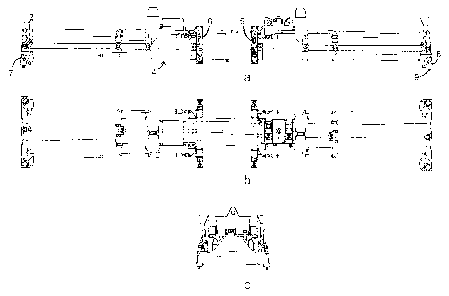
L'invention concerne un portique à conteneurs destiné à lever deux conteneurs agencés longitudinalement lequel comprend un cadre primaire (4), des poutres transversales extérieures (7, 8) disposées sur le cadre primaire (4) avec des moyens de verrouillage extérieurs (9) destinés à verrouiller les côtés courts des conteneurs tournés à l'opposé l'un de l'autre, des chariots (5, 6) disposés sur le cadre primaire (4), de telle sorte qu'ils peuvent être déplacés, un moyen de verrouillage (9) agencé sur les surfaces inférieures des chariots (5, 6) est destiné à verrouiller deux conteneurs par leurs côtés courts tournés l'un vers l'autre. Au moins un des chariots (5, 6), destinés à verrouiller les côtés courts des conteneurs tournés l'un vers l'autre, peut être déplacé essentiellement dans une direction latérale par rapport au cadre primaire, afin de pouvoir soulever des conteneurs déplacés ou des conteneurs qui sont tournés l'un par rapport à l'autre.


Abrégé anglais


A container lift intended to lift two containers arranged longitudinally that
comprises a primary frame (4), external transverse beams (7, 8) arranged on
the primary frame (4) with external locking means (9) for locking the short
sides of the containers that face away from each other, saddles (5, 6)
arranged on the primary frame (4) such that they can be displaced, locking
means (9) arranged on the lower surfaces of the saddles (5, 6) for locking two
containers with their short sides facing towards each other. At least one of
the saddles (5, 6) intended to lock the short sides of the containers that are
facing each other can be displaced in a principally sideways direction
relative to the primary frame in order to be able to lift displaced containers
or containers that are twisted relative to each other.

Revendications

Note : Les revendications sont présentées dans la langue officielle dans laquelle elles ont été soumises.


5
CLAIMS
1. A container lift intended to lift two containers arranged longitudinally
that
comprises a primary frame (4), external transverse beams (7, 8) arranged on
the
primary frame (4) with external locking means (9) for locking the shorts sides
of the
containers that face away from each other, saddles (5, 6) having lower
surfaces
arranged on the primary frame (4) such that they can be displaced, the locking
means
(9) arranged on the lower surfaces of the saddles (5, 6) for locking the two
containers
with their short sides facing towards each other, characterised in that at
least one of
the saddle (5, 6) intended to lock the short sides of the containers that are
facing each
other can be displaced in a principally sideways direction relative to the
primary frame.
2. The container lift according to claim 1, wherein the saddle (5, 6) that
belongs to
one container can be displaced sideways independently of the saddle (5, 6)
that
belongs to the second container.
3. The container lift according to claim 2, wherein the displacement is
carried out
by a hydraulic system of piston-cylinder arrangements (10, 11).
4. The container lift according to claim 3, wherein at least parts of each
saddle (5,
6) belonging to the containers are arranged such that they can be displaced
with two
of the piston-cylinder arrangements (10, 11), the pistons of which are
connected to
each other and where one cylinder is fixed attached to the primary frame and
the
second cylinder is fixed attached to the saddle: or whose cylinders are
connected with
each other and one piston (12) is fixed attached to the primary frame (4) and
the
second piston (13) is fixed attached to the saddle (5, 6).
5. The container lift according to claim 4, wherein each saddle (5, 6) on
the side
of the primary frame (4) has pegs (19) that are mounted in bearings in the
primary
frame.
6. The container lift according to claim 4, wherein the each saddle (5, 6)
comprises a locking means holder (20, 21) on the side of the primary frame
(4), which
holder is arranged at its upper end such that it can swing around an axis that
is parallel
with the primary frame (4), whereby the second cylinder is jointed connected
with the
locking means holders (20, 21) on each side of the primary frame (4) or the
second
piston is jointed connected with the locking means holders (20, 21).

6
7. The
container lift according to claim 6, wherein the piston-cylinder
arrangements (10, 11) are arranged under the primary frame (4).

Description

Note : Les descriptions sont présentées dans la langue officielle dans laquelle elles ont été soumises.


CA 02572877 2007-01-04
WO 2006/004531 PCT/SE2005/001091
1
Container lift
The invention concerns a container lift intended to be able to lift two
containers
arranged longitudinally. The invention comprises a primary frame, external
transverse beams
arranged on the primary frame with external locking means for locking the
short sides of the
containers that face away from each other, saddles arranged on the primary
frame such that
they can be displaced, inner locking means arranged on the lower surface of
the saddles for
locking of the short sides of the containers that face towards each other.
It can today be said that the use of containers dominates the transport of
goods in
large quantities. Thus the collection of containers for filling or for
emptying requires ever-
greater areas, and the containers are for this reason stacked on top of each
other, and with
gaps between them that are as small as possible. A small displacement or
twisting of one
container relative to another creates problems for a crane operator in
correctly placing a
container lift for lifting the container intended. This is a particularly
serious problem for
container lifts of the type known as "twin lift". A twist or a displacement of
two containers
relative to each other may make it impossible to correctly place the lift and
lock the
containers. Small tolerances apply, a few'tens of riiillimetres, when using
locking of the type
known as "twist lock".
One aspect of the present invention is thus to provide a container lift of the
twin lift
type with which it is possible to handle two containers that are not aligned
with each other.
The present invention is for this reason characterised by at least one of the
saddles
that are intended to lock the short sides of the containers that face each
other being
arranged such that it can be displaced in a direction that is principally
sideways relative to the
primary frame.
According to one embodiment of the ihvention, the saddle that belongs to one
of the
containers can be displaced in a sideways direction independently of the
saddle that belongs
to the second container.
According to one embodiment of the invention, the displacement is arranged to
be
carried out by a hydraulic system of piston-cylinder arrangements.
According to one particularly advantageous embodiment of the invention, the
saddle
that belongs to each of the containers i's'arranged such that it can be
displaced with two
piston-cylinder -arrangements, the pistons 'of which are connected to each
other and one
cylinder is fixed attached to the primary frame and the second cylinder is
fixed attached to
the saddle; or whose cylinders are connected with each other and one piston is
fixed
attached to the primary frame and the second piston is fixed attached to the
saddle.
The invention will now be described in more detail in the form of examples
with
reference to the drawings, where

CA 02572877 2007-01-04
WO 2006/004531 PCT/SE2005/001091
2
Figure 1 a shows a side elevation of a container lift according to the
invention;
Figure 1 b shows a plan of a container lift according to the invention;
Figure 1 c shows a view from one short side of a container lift according to
the
invention;
Figure 2 shows a cross-section of a saddle that is part of a container lift
according to
the invention, at a central location relative to the primary frame;
Fig. 3 shows a cross-section of a saddle that is part of a container lift
according to
the invention, in a position that is displaced to the right relative to the
primary frame;
Fig. 4a shows schematically one possible position of two containers that can
be
lifted with a container lift according to the invention;
Fig. 4b shows schematically a second possible position of two containers that
can
be lifted with a container lift according to the invention;
Fig. 4c shows schematically a further possible position of two containers that
can be
lifted with a container lift according to the inventi'on;
Fig. 5 shows a further embodiment of a saddle that is part of a container lift
according to the invention, at a position in which the locking means is
displaced to the left
relative to the primary frame.
Figures la-c show a container lift of twin lift type intended to be able to
carry two
containers and comprising a primary frame 4 on which saddles 5, 6, also known
as "twin lift
boxes", having the form of rings are arranged. These are shown in Figures 2
and 3 mounted
in bearings on each side of the primary frame 4 through pegs 19. The container
lift also
demonstrates at each end two outer transverse beams 7, 8. The container lift
can be locked
in a fixed position and it can support containers with the aid of known
locking means 9,
known as "twistiock" devices, at each end'of each transverse beam 7, 8 and
saddle 5, 6 on
the lower surfaces of these. The container lift with 'or without containers
can be lifted and
displaced in a manner that is known and acknowledged within the prior art
using, for
example, a crane, not shown in the drawing.
The primary frame is constituted by a design that makes it possible to adapt
the
distance between the locking means such that containers of different lengths
can be locked
in place and lifted. Furthermore, the distance between two containers that
have been lifted
can be altered during the lift. These designs are not described in any further
detail here.
As is shown in Figures 2 and 3, the saddles 5, 6 can be displaced in a
sideways
direction relative to the primary frame 4 of the container lift through a
hydraulic system. This
consists of two interacting piston-cylinder ~ arrangements 10, 11 arranged
transversely in a
horizontal direction relative to the longitudinal direction of the container
lift. One piston 12 of
the piston-cylinder arrangement 10 is fixed attached through its piston rod 17
to the primary
frame 4, while the piston 13 of the second piston-cylinder arrangement is
fixed attached to

CA 02572877 2007-01-04
WO 2006/004531 PCT/SE2005/001091
3
the saddle through its piston rod 18. The two piston rods 17, 18 are thus
directed in opposite
directions and can move freely away from each other and towards each other.
The cylinder
housing 14 consists of two cylinder chambers 15, 16 arranged subsequent to
each other, in
each of which chambers is arranged one ofthe pistons 12, 13. The cylinder
housing 14 is
mounted as a floating unit, i.e. it is not attached to anything. Each of the
cylinder chambers
has two connections for the controlled supply and withdrawal of hydraulic
fluid. Thus, each
piston-cylinder arrangement has two positions, one with an extended piston and
one with a
withdrawn piston. Since the piston-cylinder arrangements are independently
controlled, four
different combinations of these positions are possible. If one piston is
extended and the other
withdrawn, as is shown in Figure 2, independently of which, the saddle will be
centred in a
sideways direction relative to the primary frame. If both pistons are
extended, as is shown in
Figure 3, the saddle will be displaced to the right relative to the primary
frame. If both pistons
are withdrawn, the saddle will be displaced to the left relative to the
primary frame.
Each saddle (5, 6) that belongs to a container can in an embodiment that is
not
shown in the drawings be arranged such that 'it can be displaced with two
piston-cylinder
arrangements (10, 11), the pistons of which are instead connected with each
other, with one
cylinder fixed attached to the primary frame 'and the other cylinder fixed
attached to the
saddle, achieving the same effect.
Through the presence of equivalent hydraulic system in the two saddles that
are
facing each other, several positions can be achieved that are suitable for
several different
types of "erroneous" positions of two containers arranged in a longitudinal
direction. Through
displacing both saddles in the same direction, the container lift can land on
and lock
containers that are not placed with their central lines parallel, i.e.
containers that are rotated
relative to each other. If only one of the saddles is displaced, or if the
saddles are each
displaced in different directions, the container lift can' land on and lock
containers whose
central lines are parallel to each other at a distance that is equivalent to
the mutual
displacement of the saddles. The displacement thus controls the magnitude that
this distance
may reach. Since only the saddles are displaced and not the cross beams that
are arranged
at the opposite ends, an "angular error" relative to the actual locations of
the containers
arises when the saddles are displaced. The locking means, i.e. the twist lock,
however,
possesses a margin of play that compensates the "angular errors" to which the
relatively
moderate displacements give rise.
The problem of containers that are -located at an angle relative to each
other,
illustrated in Figure 4c, also is solved through one of the saddles being
displaced, or by the
saddles each being displaced in different directions.
In order to avoid the saddles becoming wedged with the pegs 19 through what is
known as the "chest of drawers" effect, a further piston-cylinder arrangement
(not shown in

CA 02572877 2007-01-04
WO 2006/004531 PCT/SE2005/001091
4
the drawing) can be arranged under each of the saddles in order to be able to
raise or lower
the saddles.
Figure 5 shows a further embodiment of the invention in which each saddle
comprises a locking means holder 20, 21 arranged such that it can swing on
each side of the
primary frame. The locking means shown in Figure 5 are displaced to the left
in the drawing
through the locking means holders being able to swing around an axis 23 at
their upper
ends, which axis is parallel to the primary frame. The piston-cylinder
arrangements are
arranged in this embodiment under the primary frame. The piston 12 of one
piston-cylinder
arrangement 10 is attached through its piston rod 17 to the primary frame 4,
while the piston
13 of the second piston-cylinder arrangement 11 is jointed attached through
its piston rod 18
to both of the locking arrangement holders 20, 21 at the axes 22. The
displacements or
movements of the locking means holders are controlled in a manner that is
equivalent to that
in the embodiment according to Figures 2'and 3.
The extent of protection is not to be regarded as limited to the examples
described
in the description: it includes a number' of embodiments that are conceivable
within the
framework of the claims for one skilled in the arts.

Dessin représentatif
Une figure unique qui représente un dessin illustrant l'invention.
États administratifs

2024-08-01 : Dans le cadre de la transition vers les Brevets de nouvelle génération (BNG), la base de données sur les brevets canadiens (BDBC) contient désormais un Historique d'événement plus détaillé, qui reproduit le Journal des événements de notre nouvelle solution interne.

Veuillez noter que les événements débutant par « Inactive : » se réfèrent à des événements qui ne sont plus utilisés dans notre nouvelle solution interne.

Pour une meilleure compréhension de l'état de la demande ou brevet qui figure sur cette page, la rubrique Mise en garde , et les descriptions de Brevet , Historique d'événement , Taxes périodiques et Historique des paiements devraient être consultées.

Historique d'événement

Description Date
Le délai pour l'annulation est expiré 2024-01-04
Lettre envoyée 2023-07-04
Lettre envoyée 2023-01-04
Lettre envoyée 2022-07-04
Demande visant la nomination d'un agent 2021-03-19
Requête pour le changement d'adresse ou de mode de correspondance reçue 2021-03-19
Demande visant la révocation de la nomination d'un agent 2021-03-19
Représentant commun nommé 2019-10-30
Requête pour le changement d'adresse ou de mode de correspondance reçue 2018-01-16
Accordé par délivrance 2013-07-02
Inactive : Page couverture publiée 2013-07-01
Préoctroi 2013-04-18
Inactive : Taxe finale reçue 2013-04-18
Un avis d'acceptation est envoyé 2012-10-29
Lettre envoyée 2012-10-29
Inactive : Approuvée aux fins d'acceptation (AFA) 2012-10-25
Modification reçue - modification volontaire 2012-08-24
Inactive : Dem. de l'examinateur par.30(2) Règles 2012-02-28
Lettre envoyée 2010-06-30
Requête d'examen reçue 2010-06-15
Exigences pour une requête d'examen - jugée conforme 2010-06-15
Toutes les exigences pour l'examen - jugée conforme 2010-06-15
Lettre envoyée 2008-06-13
Inactive : Déclaration des droits - Formalités 2008-04-15
Inactive : Transfert individuel 2008-04-15
Inactive : Lettre officielle 2008-04-09
Inactive : Page couverture publiée 2007-03-08
Inactive : Lettre de courtoisie - Preuve 2007-03-06
Inactive : Notice - Entrée phase nat. - Pas de RE 2007-03-01
Demande reçue - PCT 2007-02-02
Exigences pour l'entrée dans la phase nationale - jugée conforme 2007-01-04
Demande publiée (accessible au public) 2006-01-12

Historique d'abandonnement

Il n'y a pas d'historique d'abandonnement

Taxes périodiques

Le dernier paiement a été reçu le 2013-06-11

Avis : Si le paiement en totalité n'a pas été reçu au plus tard à la date indiquée, une taxe supplémentaire peut être imposée, soit une des taxes suivantes :

  • taxe de rétablissement ;
  • taxe pour paiement en souffrance ; ou
  • taxe additionnelle pour le renversement d'une péremption réputée.

Veuillez vous référer à la page web des taxes sur les brevets de l'OPIC pour voir tous les montants actuels des taxes.

Titulaires au dossier

Les titulaires actuels et antérieures au dossier sont affichés en ordre alphabétique.

Titulaires actuels au dossier
ELMHULTS KONSTRUKTIONS AB
Titulaires antérieures au dossier
GOESTA KARLSSON
Les propriétaires antérieurs qui ne figurent pas dans la liste des « Propriétaires au dossier » apparaîtront dans d'autres documents au dossier.
Documents

Pour visionner les fichiers sélectionnés, entrer le code reCAPTCHA :


Pour visualiser une image, cliquer sur un lien dans la colonne description du document. Pour télécharger l'image (les images), cliquer l'une ou plusieurs cases à cocher dans la première colonne et ensuite cliquer sur le bouton "Télécharger sélection en format PDF (archive Zip)" ou le bouton "Télécharger sélection (en un fichier PDF fusionné)".

Liste des documents de brevet publiés et non publiés sur la BDBC .

Si vous avez des difficultés à accéder au contenu, veuillez communiquer avec le Centre de services à la clientèle au 1-866-997-1936, ou envoyer un courriel au Centre de service à la clientèle de l'OPIC.


Description du
Document 
Date
(aaaa-mm-jj) 
Nombre de pages   Taille de l'image (Ko) 
Revendications 2007-01-04 1 56
Description 2007-01-04 4 234
Dessins 2007-01-04 4 92
Abrégé 2007-01-04 1 71
Dessin représentatif 2007-03-07 1 19
Page couverture 2007-03-08 1 52
Revendications 2012-08-24 2 52
Dessin représentatif 2012-10-29 1 15
Page couverture 2013-06-11 1 48
Rappel de taxe de maintien due 2007-03-06 1 110
Avis d'entree dans la phase nationale 2007-03-01 1 192
Courtoisie - Certificat d'enregistrement (document(s) connexe(s)) 2008-06-13 1 104
Rappel - requête d'examen 2010-03-08 1 119
Accusé de réception de la requête d'examen 2010-06-30 1 177
Avis du commissaire - Demande jugée acceptable 2012-10-29 1 162
Avis du commissaire - Non-paiement de la taxe pour le maintien en état des droits conférés par un brevet 2022-08-15 1 541
Courtoisie - Brevet réputé périmé 2023-02-15 1 537
Avis du commissaire - Non-paiement de la taxe pour le maintien en état des droits conférés par un brevet 2023-08-15 1 540
Taxes 2012-06-20 1 156
Taxes 2013-06-11 1 156
PCT 2007-01-04 2 78
Correspondance 2007-03-01 1 27
Taxes 2007-07-03 1 21
Correspondance 2008-04-09 2 36
Correspondance 2008-04-15 1 31
Taxes 2009-06-22 1 40
Correspondance 2013-04-18 2 49