Note : Les descriptions sont présentées dans la langue officielle dans laquelle elles ont été soumises.
CA 02574352 2007-01-18
Attorney Docket No. 027262-205
METHOD OF PRODUCING HELICALLY CORRUGATED
METAL PIPE AND RELATED PIPE CONSTRUCTION
TECHNICAL FIELD
[0001] This application relates generally to helically corrugated metal pipe
commonly
used in drainage applications and, more specifically, to a method of producing
such pipe with
improved diameter control and/or end connection features.
BACKGROUND
10002] The standard production process for producing helically corrugated
metal pipe is
well known and involves first forming lengthwise corrugations in an elongated
strip of sheet
metal, with the corrugations extending along the length of the strip. The
corrugated strip is then
spiraled into a helical form so that opposite edges of the corrugated strip
come together and can
be either crimped or welded to form a helical lock along the pipe. Diameter
control of the
resulting pipe is regularly an issue in the manufacturing process and is
important to the
functionality of the pipe from an installation standpoint when pipes are being
connected end to
end at a job site in the field. Attempts to address diameter control have been
made in the past.
U.S. Patent Nos. 3,940,962, 3,417,587, 4,287,739 and 4,438,643 describe pipe
manufacturing
techniques and related equipment. Improvements are continually sought.
[0003] Joining lengths of helically corrugated metal pipe creates issues in
the field. U.S.
Patent No. 5,842,727 teaches a coupling member that can be used to join the
ends of two pipes in
a sealed manner. Improvements in the area of pipe coupling would be
advantageous as the same
could reduce pipe installation costs.
SUMMARY
[0004] A system and method for pipe size or diameter control in connection
with the
production if helically corrugated pipe is provided. Advantageous pipe
configurations may be
achieved. Pipe size monitoring and control may be automated.
BRIEF DESCRIPTION OF THE DRAWTNGS
[0005] Fig. 1 is a top plan schematic of a pipe manufacturing device;
[0006] Fig. 2 is a cross-section of an exemplary corrugated metal strip taken
along line 2-
1
CA 02574352 2007-01-18
Attorney Docket No. 027262-205
2 of Fig. 1;
[0007] Fig. 3 is an exemplary cross-section of a lockseam;
[0008] Fig. 4 is an exemplary control system configuration for the device of
Fig. 1;
[0009] Fig. 5 shows exemplary pipe with unitary bell end and unitary spigot
end;
[0010] Fig. 6 shows a spigot end of one pipe within a bell end of another
pipe;
[0011] Fig. 7 depicts exemplary pipe diameter profiles;
[0012] Figs. 8 and 9 illustrate an exemplary pressure roller and drive
assembly;
[0013] Fig. 10 illustrates an exemplary pipe diameter monitoring device;
[0014] Fig. 11 is a schematic illustration showing a pair of lockseam rollers
and a
pressure roller;
[0015] Fig. 12 is a schematic depiction of a pipe having a larger diameter end
and a
smaller diameter end; and
[0016] Fig. 13 is a schematic depiction of another embodiment of a pipe
assembly.
DETAILED DESCRIPTION
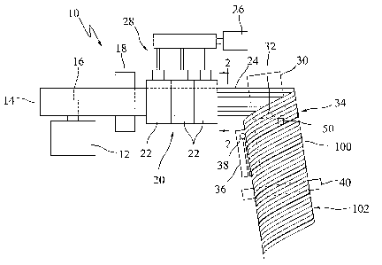
[0017] Referring to Fig. 1, a pipe manufacturing line or device 10 is shown in
top plan
schematic form. The device 10 includes a decoiler unit 12 for receiving a coil
14 formed by a
rolled metal sheet. The illustrated decoiler unit 12 supports the coil 14 on a
rotatable expansion
mandrel 16, permitting the coil to rotate during pipe manufacture. A weld
table 18 is shown
downstream of the decoiler unit 12 and is provided for welding the end of one
metal sheet to the
end of the metal sheet of a different coil upon coil replacement. A
corrugating line 20 includes a
number of corrugators 22 for drawing the metal sheet off of the coil 14 and
placing corrugations
in the metal sheet to produce a corrugated metal strip 24. The metal sheet
passes between upper
and lower corrugating rollers in each of the corrugators 22 and the. rollers
apply pressure to the
sheet to form corrugations. By way of example, first corrugator 22 may form a
middle
corrugation in the strip, next corrugator 22 may form second and third
corrugations alongside the
previously formed middle corrugation, next corrugator 22 may form fourth and
fifth corrugations
alongside the previously formed second and third corrugations, and so on, with
the number of
corrugators varying as necessary. However, variations on the operation of the
corrugators are
2
CA 02574352 2007-01-18
Attorney Docket No. 027262-205
possible. The corrugations may be of any suitable shape and configuration. In
one embodiment,
the pipe manufacturing device operates to produce hydraulically efficient pipe
such as that
described in U.S. Patent No. 4,838,317, in which case the corrugated metal
strip may have a
cross-section similar to that generally shown in Fig. 2, where the
corrugations 11 are shown with
a generally rectangular or box-shape and the side edges of the corrugate metal
strip 24 includes
respective lips 13 and 15 for use in producing the helical lockseam described
below. The exact
configuration of locking lips 13 and 15 can vary.
[0018] The rollers of the illustrated corrugators 22 are driven by an electric
motor 26
with its output linked to a gearbox/transmission arrangement 28. A forming
head 30 is
positioned to receive the corrugated metal strip 24 and includes a lockseam
mechanism 32
located at a pipe exit side 34 of the forming head. The forming head 30 may be
a well known
three-roll forming head configured to spiral the corrugated metal strip 24.
The lockseam
mechanism 32 locks adjacent edges of the spiraled corrugated metal strip in a
crimped manner to
produce a helical lockseam 100 in the resulting pipe 102. Specifically, as the
corrugated metal
strip is helically curved back upon itself to form the pipe-shape, the locking
lips 13 and 15 come
together before passing into the lockseam mechanism 32, and the lockseam
mechanism 32
presses the lips together to produce a lockseam that may, in one example, have
the general
appearance of that shown in the cross-section of Fig. 3. Referring to Fig. 11,
in one embodiment
the lockseam mechanism 32 is formed by an upper lockseam roller 104 and a
lower lockseam
roller 106. The engaged locking lips 13 and 15 of the spiraled strip pass
between these rollers
where the crimping operation is performed. As an alternative to the lockseam
mechanism, a
weldseam mechanism could be provided to join adjacent edges of the strip to
form a helical
weldseam.
[0019] Referring back to Fig. 1, a saw unit 36 is positioned along the pipe
exit path and
includes a saw 38 that is movable into and out of engagement with the pipe 102
and that is also
movable along a path parallel to the pipe exit path so that the pipe can be
cut even while pipe
continues to be produced. Pipes with a variety of diameters can be formed by
the device 10, and
large scale diameter control is made by adjusting an entry angle of the
corrugated metal strip 24
3
CA 02574352 2007-01-18
Attorney Docket No. 027262-205
to the fonning head 30. Such angle adjustment can be achieved by either by
rotating the forming
head 30 relative to a stationary corrugation line 20 or by rotating the
corrugation line 22, weld
table 18 and decoiler unit 12 relative to a stationary forming head 30. A
variety of systems such
as that generally described above have long been used and are available from,
for example,
Pacific Roller Die of Hayward, California and IMW Industries of Chilliwack,
British Columbia,
Canada.
[0020] The pipe manufacturing device 10 also includes a pipe size monitoring
device 40
along the pipe exit path, in this case shown downstream of the saw unit 36.
However, the pipe
size monitoring device 40 could also be located upstream of the saw unit 36.
While helically
corrugated pipe is generally specified, along with other parameters, by length
and diameter, the
term "diameter" can be difficult to apply to the pipe with absolute technical
accuracy because the
pipe may actually be slightly out of round. The term "pipe size" is used
herein to broadly refer
to any of a perimeter (inner or outer) dimension of the of the pipe, a
diameter dimension of the
pipe, or some other dimension of the pipe that is reflective of the flow
capacity of the pipe, but
the term "pipe size" specifically does not include pipe length. As used herein
the term
"diameter" applies even to pipe that may be out of round, in which case the
diameter may be an
average radial dimension measured from a generally centrally located axis of
the pipe.
[00211 The pipe size monitoring device 40 can be used to provide automated
pipe size
control for pipe 102 as it is produced. Specifically, the device 10 may
include an internal
pressure roller 501ocated downstream (Fig. 1) and slightly offset laterally of
the lockseam rollers
104 and 106 as shown in Fig. 11. As demonstrated schematically by Fig. 11, the
pressure roller
50 is located for rolling contact with an inner surface 110 of the pipe 102.
In one example the
pressure roller is positioned such that it rolls over the inner side of one of
the box-shaped
corrugations 11. The pressure roller 50 is movable along a vertical path 52 so
that the radially
outward pressure applied to the inner surface 110 can be varied. Due in part
to the relative
positioning of the pressure roller 50 between the seaming roll location 51 and
the buttress roll
location 53 (both of which are part of the forming head), when the pressure
roller 50 is moved
downward (e.g, to position shown by the dashed line circle) the pressure
roller 50 causes the
4
CA 02574352 2007-01-18
Attorney Docket No. 027262-205
"next coil" of pipe to be pulled into the lockseam slighly faster, or in other
words with a slightly
tighter or smaller curvature (as reflected in an exaggerated sense by dashed
line strip 55), causing
the pipe size to decrease. On the other hand, when the pressure roller 50 is
moved upwards, the
next coil of pipe is pulled into the lockseam slightly slower, or in other
words with a slightly
looser or larger curvature, causing the pipe size to increase. Tightening or
decreasing the
curvature of the pipe results in an effective increase in the instantaneous
helix angle of the pipe
and loosening or enlarging the curvature of the pipe results in an effective
decrease in the
instantaneous helix angle of the pipe.
[0022] Referring now to Fig. 4, a schematic representation of an exemplary
control
system of the pipe manufacturing device 10 is provided. The pipe size
monitoring device 40
provides an output 42 that is indicative of the pipe size as the pipe is being
produced. The output
42 may vary regularly to reflect pipe size changes as they occur. In one
embodiment the output
42 is indicative of pipe size by way of an analog or digital signal that
actually contains the pipe
size information. In another embodiment the output 42 is indicative of pipe
size by reflecting
changes from a set point, those changes being convertible to an actual pipe
size by suitable
processing. Either way, a control unit 44 may receive the output 42 and
responsively effect
operation of an automated drive mechanism 54 that adjusts the position of the
pressure roller 50.
Thus, it is seen that the device 10 provides for automated control of pipe
size (e.g., diameter) by
providing a feedback arrangement of monitored pipe size. In one example, the
pressure roller 50
and related drive 54 may be configured to provide diameter control within a
tolerance of about
one fourth of one percent (0.25%) or better of total pipe diameter, such as
about one sixth of one
percent (0.167%) or better of total pipe diameter or about one eighth of one
percent (0.125%) or
better of total pipe diameter. Thus, it is seen that the device 10 provides
advantageous pipe size
or diameter control during pipe production.
[0023] In one embodiment the control unit 10 is configured to provide pipe
size control
of at least two types. Specifically, in a first mode the control unit 44
effects operation of the
automated drive 54 so as to maintain a substantially constant pipe size during
pipe production
(e.g, by comparing a measured pipe size to a desired pipe diameter stored in
niemory of the
CA 02574352 2007-01-18
Attorney Docket No. 027262-205
control unit and effecting operation of the drive 54 when the measured pipe
size moves outside
of a certain range about the desired pipe size, or by comparing a monitored
pipe size variation to
a permissible variation stored in memory and effecting operation of the drive
54 when the
monitored pipe size variation exceeds the permissible variation). In a second
mode the control
unit 44 effects operation of the automated drive 54 so as to intentionally
vary pipe size during
pipe production (e.g., by comparing the measured pipe size to a desired
diameter as indicated by
a desired pipe diameter profile stored in memory, or by comparing monitored
pipe size variation
to a desired variation profiled stored in memory). Selection of either the
first mode or the second
mode may be made via a user interface associated with the control unit 44. In
one embodiment
the user interface may take the form of a touch screen display 46 that
displays visual interface
keys that an operator can touch and trigger. However, the user interface could
also take other
forms, such as a standard display in combination with a keypad. In either
case, during pipe
production the display may 46 provide a continuously updated visual display of
measured pipe
size or diameter and/or of variance of pipe size or effective diameter from a
desired pipe size.
[0024] In one example of the above-mentioned second mode, pipe production is
controlled so that a resulting pipe has one end with a larger diameter than
its opposite end.
Referring to Fig. 12 where the profile of such a pipe is shown schematically,
a helix angle a1
toward larger diameter end 300 is larger than a helix angle a2 toward smaller
diameter end 302,
where the helix angle is taken at instantaneous locations along the lockseam
and is reference
from a central pipe axis 304. It may be difficult to observe the helix angle
difference between
opposite pipe ends where the pipe size is large and the diameter difference
between the two ends
of the pipe is only a couple of inches or less.
[0025] The pipe, with ends of different diameters, can then be worked further
to produce
a pipe configuration with advantageous bell and spigot connecting ends.
Specifically, the larger
diameter end of the pipe may be worked so as to produce a substantially
corrugation free bell end
120 and the downstream end is worked to produce a spigot end 122, as shown in
Fig. 5 where the
bell end 120 and spigot end 122 are shown facing each other for ease of
relative discussion. The
bell end 120 includes an outwardly flared entry lip 124 at the end edge of
generally cylindrical
6
CA 02574352 2007-01-18
Attorney Docket No. 027262-205
portion 126. At the opposite end edge of generally cylindrical portion 126 one
or more annular
corrugations 128 are also formed. The spigot end 122 is formed with one or
more annular
corrugations so as to provide an annular gasket seat 130. Notably the very
edge of the spigot end
122 flares outwardly.' The inner diameter D1 of the bell end 120 is slightly
larger than the outer
diameter D2 of the spigot end 122, enabling the spigot end 122 of one pipe to
be readily inserted
into the bell end 120 of another pipe as reflected in Fig. 6. In one example,
the inside diameter
D1 of the bell end is at least about 1/3" greater than the outside diameter D2
of the spigot end
122. In another example, D 1 is at least about %z" greater than D2. Variations
are possible. Also
shown is a gasket 132 positioned in gasket seat 130 so as to seal with the
inside surface of bell
end portion 126. The internal portion of annular corrugation 128 provided
adjacent the
cylindrical portion 126 of bell end 120 serves as an abutment or stop that
contacts the outwardly
flared spigot end 122 so that entry of the spigot end into the bell end 120 is
limited. [0026] In one example, an axial length of cylindrical portion 126 is
at least about four
inches, while in another example an axial length of portion 126 is at least
about six inches.
Variations are possible.
[0027] The working of the end of the pipe to form the spigot end may be
achieved using
a suitably formed recorrugator, which is a device known in the art. Likewise,
the working of the
end of the pipe to form the bell end may start by using a recorrugator to form
annular
corrugations at the pipe end. The resulting annular corrugations at the very
end of the pipe are
then eliminated to form cylindrical portion 126 by a similar rerolling
process. Alternatively, one
or more annular corrugations may be formed in position slightly spaced apart
from the end of the
pipe and the remaining helical corrugations at the end of the pipe may be
eliminated by rerolling
to form cylindrical portion 126.
[0028] The device 10 can be used in a process to form multiple helically
corrugated
metal pipe segments of similar length that are readily connectable end to end.
Specifically, the
method involves: (a) drawing a metal sheet off of a coil; (b) corrugating the
metal sheet to
produce a corrugated metal strip; spiraling the corrugated metal strip and
locking adjacent edges
of the spiraled corrugated metal strip in a crimped manner to produce a
helical lockseam; (d)
7
CA 02574352 2007-01-18
Attorney Docket No. 027262-205
automatically monitoring pipe size of pipe being produced; (e) based upon the
pipe size
monitoring, automatically varying helix angle of the pipe as it is produced in
a manner to
intentionally vary pipe diameter; (f) producing multiple pipe segments by
cutting the helically
corrugated metal pipe each time a specified length of pipe is produced; (g)
coordinating the pipe
diameter variations of step (e) with the cutting operations of step (f) such
that pipe segments are
produced in the following sequence in a repeating manner: (1) producing a pipe
segment having
a downstream end and an upstream end, a diameter of the upstream end larger
than a diameter of
the downstream end, then (2) producing a pipe segment having a downstream end
and an
upstream end, a diameter of the upstream end smaller than a diameter of the
downstream end.
As a general rule the diameter of the upstream end of each pipe segment of
(g)(1) will be
substantially the same as the diameter of the downstream end of each pipe
segment of (g)(2).
For each pipe segment of (g)(1), the upstream end is rerolled or otherwise
worked to produce a
substantially corrugation free bell end, and the downstream end is rerolled or
otherwise worked
to produce a spigot end with at least one annular corrugation. For each pipe
segment of (g)(2),
the downstream end is rerolled or otherwise worked to produce a substantially
corrugation free
bell end, and the upstream end is rerolled or otherwise worked to produce a
spigot end with at
least one annular corrugation.
[0029] The diameter control from end to end of each pipe segment may be in
accordance
with a diameter profile stored in memory of the control unit. Two exemplary
diameter profiles
are shown in Fig. 7. In profile 150 the pipe diameter is controlled in a
substantially linear
manner between diameters DA and DB, with the pipe being cut at points 152
along the profile. In
profile 154 the pipe diameter is controlled so that the diameter is
temporarily held stable, at
either diameter Dc or DD, before and after each of the cut points 152. Other
profiles could also
be developed and used without departing from the scope of this application.
[0030] Referring now to Figs. 8 and 9, an exemplary pressure roller assembly
and
associated automated drive 54 are shown. Pressure roller 50 is rotatably held
between end
brackets 160 and 162 that extend from a support assembly 164. Support assembly
164 includes
at least two members threadedly engaging each other, where one of the members
is rotatable but
8
CA 02574352 2007-01-18
Attorney Docket No. 027262-205
has a fixed position along vertical axis 166 and the other member is non-
rotating but is movable
along axis 166. A servomotor 168 is provided to effect rotation of the
rotatable member via a
chain and sprocket arrangement or a belt and pulley arrangement 170. The
smaller
pulley/sprocket 172 transfers the rotation to a larger pulley/sprocket 174 to
effect rotation of the
rotatable member of support assembly 164. The size and pitch of the threads of
the support
assembly members, the relative size of the pulleys/sprockets 172 and 174 and
the precision of the
servomotor 168 can be selected to provide a desired level of controllability
and tolerance for
position of the pressure roller 50. The entire pressure roller assembly can be
supported off of the
end of the pipe forming head 30 (Fig. 1) so as to be located internal of the
pipe as it is produced.
[0031] Referring now to Fig. 10, an exemplary pipe size monitoring device 40
is shown
and includes steel frame with a base 180 and upright side supports 182 and
184. Atop support
182 is a ring member 185 and atop support 184 is a rotatable pulley 186
supported on axis 190,
A tension line 192 (such as a wire, band or rope) has one end fixed to the
ring 185 and loops
about the pipe that moves along the pipe exit path. The tension wire 192
extends to pulley 186
and is fixed for rotation with the pulley 186 by a wire locking screw 194. A
tensioning ann 196
is pivotably connected with the pulley 186 at axis 198 and is also pivotably
connected at a non-
moving location 200 along an upright guide bar 202. A linear transducer 204
includes one end
206 pivotably connected with the tensioning arm 196 and its opposite end 208
pivotably
connected to a horizontal support 210. A spring member 212 extends between the
tensioning
arm 196 and the horizontal support 210 to bias the pulley 186 in the
counterclockwise direction
reflected by arrow 214. A wire source 215, such as a wire spool, is also
shown. During pipe
manufacture, increases in the diameter of the pipe are translated into
rotation of the pulley 186 in
the clockwise direction of the pulley 186 as reflected by arrow 216, resulting
in an extension of
the linear transducer 204. Conversely, decreases in the diameter of the pipe
are translated into
rotation of the pulley 186 in the counterclockwise direction of the pulley 186
as reflected by
arrow 214, resulting in a retraction or shortening of the linear transducer
204. The linear
transducer 204 outputs an electrical signal that varies with its length. Thus,
pipe diameter
variations are reflected by signal changes from the transducer 204, that can
be provided to the
9
CA 02574352 2007-01-18
Attorney Docket No. 027262-205
above-mentioned control unit 44 (Fig. 4). When it is desired to change from
measuring a
relatively small diameter pipe to a relatively large diameter pipe, the wire
locking screw 194 is
released to allow sufficient wire or other line to feed past the pulley 186
for extending about the
larger pipe diameter, and the wire locking screw 194 is again rotated to lock
the wire in place for
movement with the pulley 186. Other types of pipe size monitoring devices
could also be used.
As used herein "diameter variations" or "pipe size variations" can be
reflected in a signal that
contains an absolute diameter or pipe size measurement or in a signal that
simply departs from a
reference level.
[0032] It is recognized that the position of the pressure roller 50 could also
be controlled
by operator (e.g., by pushing an up or down button or by rotating a knob) in
response to an
indication on the operator display indicating that pipe diameter is moving or
has moved out of
tolerance.
[0033] Referring now to Fig. 13A, one end of a helically corrugated pipe 400
is shown
with a bell end fitting 402 attached thereto. The end of the pipe 400 is
rerolled to eliminate the
helical corrugations but to leave at least one annular gasket seat 404 into
which an annular gasket
406 is placed. The annular gasket 404 might alternatively be located in the
annular corrugation
405 located closer to the end of the pipe. One end 408 of the bell fitting 402
is configured to
slide onto the end of the pipe 400 and to engage the gasket 406. In the
illustrated embodiment
fitting end 408 include an outwardly turned lip or flange. The bell fitting
402 is held on the end
of the pipe by a shrink wrap material, the position of which prior to heat
shrinking is shown by
solid line 410 and the position of which after heat shrinking is shown by
dashed line 412. This
pipe assembly can be produced in the plant so as to avoid the need to deal
with heating the shrink
wrap in the field. Specifically, the helically corrugated pipe 400 is produced
and it end is
rerolled to form the annular gasket seat 404. The annular gasket 406 is then
positioned in the
seat. The bell fitting 402 is typically manufactured with a diameter to assure
it can readily slide
onto the end of the pipe 400, but not so large as to have excessive play
relative to the end of the
pipe. Once the bell fitting is slid onto the end of the pipe into the desired
position relative to the
gasket 406, the shrink wrap is wrapped around the pipe as generally shown at
410. Next, the
CA 02574352 2007-01-18
Attorney Docket No. 027262-205
pipe assembly can be passed by a suitable hot air heating system to cause the
shrink wrap to
shrink, thereby securely holding the bell fitting on the end of the pipe and
assuring a good seal.
In some embodiments is may be possible to eliminate the gasket 406 and to rely
upon shrink
wrap material alone to form a suitable seal, particularly where the shrink
wrap material is
positioned so as to shrink tightly over at least one annular corrugation crest
or other annular
formed ring on each of the pipe end and the bell fitting end.
[0034] The opposite end of the pipe 400 may be configured to be a spigot end
as
generally shown in Fig. 13B, with the end rerolled to provide an annular
gasket seat 420. In the
field, as pipes are being connected end to end, a gasket 422 is placed in the
gasket seat 420 of the
spigot end of one pipe and the spigot end is then pushed into the bell end
(formed by the bell
fitting) of the other pipe. The gasket 420 forms a suitable seal between the
spigot end and bell
end. The bell fitting may include an inwardly extending lip or corrugation 424
against which the
end face 426 of the spigot end of a pipe will abut, providing a simple manner
of assuring that
spigot ends are inserted into bell ends properly.
[0035] It is to be clearly understood that the above description is intended
by way of
illustration and example only and is not intended to be taken by way of
limitation, and that
changes and modifications are possible. Accordingly, other embodiments are
contemplated.
[0036] What is claimed is:
11