Note : Les descriptions sont présentées dans la langue officielle dans laquelle elles ont été soumises.
CA 02575450 2007-01-26
WO 2006/022653 PCT/US2004/024404
METHOD AND APPARATUS FOR LASER INSCRIPTION OF AN IMAGE
ON A SURFACE
Field of the Invention
The invention relates to the inscription of images on a surface and more
particularly to a
method and apparatus for creating permanent images on glass and other
inorganic oxide containing
surfaces using high energy light.
Background of the Invention
The inscription of images ori various surfaces has become increasingly
important in recent
years for the permanent identification of valuable objects in addition to
forming decorative designs
on surfaces. For example, for the permanent identification of automobiles,
trucks and the like,
vehicle VIN Numbers or other identifying indicia are permanently inscribed on
the windows of the
vehicle at various locations to provide a non-removable identification for the
vehicle. Many
insurance companies offer a discount from the cost of insuring the vehicle if
such permanent indicia
are placed on the vehicle. Such indicia, for example a bar code, can also
provide an access code for
the retrieval of the history of the vehicle, such as for example its previous
owner, its maintenance
history and the like.
Conventionally, the inscription process is accomplished by mechanical or
chemical means. For
example, a malleable surface, such as wood, certain precious metals and the
like, can be
mechanically iriscribed using a router or similar tool. These tools can be
manually operated by
persons possessing relatively high degree of skill or can be robotically
controlled to mass produce
inscriptions of various kinds on the malleable surface. However, manual
operation is slow and not
suited to repetitive operations while robotic equipment is expensive and can
present a substantial
CA 02575450 2007-01-26
WO 2006/022653 PCT/US2004/024404
2
maintenance problem.
In the case of hard surfaces such as glass, chemical etching utilizing a
stencil is a common
method employed for the inscription of indicia on the surface of the glass.
Asuitable'etchant is
placed on the back of the stencil and the etchant contacts the glass surface
through the openings in
the stencil. The etchant chemically attacks the surface to permanently etch an
image corresponding
to the stencil openings into the glass surface. Examples of such methods are
represented by U.
S.Patent 4,585,514 granted April 29, 1986 to L. Joe Scallan and U. S. Patent
4,985,115 granted
January 15, 1991 to Thomas DeRossett. Both of these employ chemical etchants
to etch an image
into the surface of glass.
It is well understood, however, that glass and other inorganic oxide
containing materials are
relatively chemically resistant. Therefore, the etchant must be of a highly
corrosive nature in order
to react with the glass surface to form an image. Most of the etchant
compounds are hydrogen
fluoride based and as such, are highly corrosive and dangerous to use. Also,
disposal of such
materials can also be a serious problem in view of the potentially harmful
environmental affect such
materials may have. These materials must be treated as toxic substances and
disposed of only at
approved sites and transported in an approved manner. Needless to say the
disposal of toxic materials
is an expensive operation.
As an alternative to the chemical etch, sandblasting can be utilized as a
method for etching
glass and other similar surfaces. Sandblasting, if not properly carried out,
also posses an
environmental threat as well as a potential safety hazard to the operators and
other personnel in the
immediate area of the sandblasting operation. It is necessary to provide
adequate protection for the
operators of the sandblasting equipment as well as expensive air filtering
apparatus to avoid air
pollution violations.
Neither chemical etching nor sandblasting readily lend themselves to
automation and in most
cases, the indicia which can be etched onto the glass surface are limited to
non-machine readable
numbers. Moreover, poor technique, particularly in the case of chemical
etching, can lead to
CA 02575450 2007-01-26
WO 2006/022653 PCT/US2004/024404
3
erroneous results due to blurring of the etched image making it difficult to
read, especially by
machine. It must be noted, particularly in the case of automobile VIN numbers,
that accuracy and
image quality are of the utmost importance and mistakes require the
replacement of the vehicle
window or windshield, an expensive procedure. .
Accordingly, laser etching or inscription of indicia has become a method of
choice,
particularly for the permenent inscription of indicia such vehicle VIN
numbers. U.S. Patent
5,298,717, issued March 29, 1994 in the name of Thomas Derossett is an example
of a laser etching
system and apparatus for the permanent inscription of vehicle VIN numbers on
areas of the vehicle
glass, such as a lower non-interfering portion of the windshield or side
windows. Derossett describes
apparatus utilized to carry out the laser inscription of a surface, including
auto safety glass that
includes an emitter housing in which the laser emission source is located. The
emitter housing
further includes control means for controlling the output beam to form the
desired pattern. A
marking head separate from the emitter housing electronically and optically
communicates with the
emitter housing. Beam directing means in the marking head are electronically
connected to the
control means in the emitter housing to direct the beam from the emission end
of the marking head
over the surface to etch the desired pattern. The marking head optically
communicates with the
emitter housing by a flexible arm defining an enclosed optical path from the
emitter housing for
conducting the emission beam to the marker head. While the Derossett apparatus
is successfully used
to inscribe VIlV numbers the apparatus requires frequent time consuming
adjustments to the optical
path in order to insure correct alignment of the laser beam. In addition,
replacement of marking
heads can be time consuming due to the necessity of assembling the new marking
head and the
flexible optical path and aligning the laser beam with the optical path and
the marking head.
Summary of the Invention
As used herein, the terms etch and etching are defined as any process for the
permanent
inscription of an image into.a surface be it a chemical or physical process,
including the use of high
CA 02575450 2007-01-26
WO 2006/022653 PCT/US2004/024404
4
energy light.
It is an object of the present invention to provide an improved apparatus for
the laser
inscription of indicia onto a surface.
Another object of the present invention is to provide apparatus for etching
surfaces which
can be operated by a minimum of personnel in a safe and efficient manner.
Still another object of the invention is to sliorten the light path from the
laser to the surface
being etched.
Yet another object of the invention is to provide apparatus for laser
inscription of a surface
that requires less maintenance.
These and other objects and features of the present invention are achieved by
the present
invention by which an image is inscribed into surface employing a laser
generated high intensity
beam. An emitter includes a laser that, in response to a firing signal
initiated by the operator, emits
a high intensity beam of light that is communicated to marking head that is
pivotally mounted on the
housing in which the laser source is located. The beam is controllably
directed by the marking head
onto the surface being etched to scribe an image representing the input data
into the surface.
In one embodiment ofthe invention the surface being etched in accordance with
the invention
comprises glass or other inorganic oxide containing materials which may be
transparent to the laser
output. Accordingly, a laser having an emission to which glass is not
transparent must be used. For
example, eximer and C02 type lasers provide an emission beam which is highly
effective for etching
glass. In addition to the C02 and eximer laser, other laser emission sources,
such as the YAG laser,
are suited for use in this invention where the material being etched is not
transparent to the emission
beam. Such materials include wood, plastics and metal alloys. It will be
understood, therefore, that
the selection of laser emission source is a matter of choice depending upon
the surface being etched
as is well understood in the art.
The apparatus utilized to carry out the foregoing method includes an emitter
housing in which
CA 02575450 2007-01-26
WO 2006/022653 PCT/US2004/024404
the laser emission source is located. A marking head is pivotally affixed to
the emitter housing and
electronically and optically communicates therewith. Beam directing apparatus
in the marking head
is electronically connected to a controller to receive and process the signals
foi controlling the beam
directing apparatus to move the laser beam over the surface to etch the
desired pattern. Preferably,
5 the marking head is provided with one or more suction devices for securing
the marking head in
proper alignment and spacing with the surface being etched and interlocks are
provided to prevent
the firing of the laser until the marking head is correctly positioned with
respect to the surface to be
etched.
In a preferred embodiment means are provided to draw a vacuum at the marker
head during
the etching process as an aid in securing the marker head against the surface
being etched.
While the emitter housing and marking head are separate units, the marking
head is located
immediately adjacent to the laser source to shorten the optical path for the
laser beam. The marking
head is pivotally carried by the emitter housing for pivoting movement in
relation to the emitter
housing. The marking head may be mounted on either sidewall or the top or
bottom wall of the
emitter housing.
A controller electronically communicates with the marking head and is
programmed, such
as by suitable software, for issuing control signals representing the x and y
coordinates of the
emission beam to the marking head. Responsive to the coordinates, the emission
beam is directed
over the target area to form the desired pattern. A preferred means for
directing the emission beam
comprises motor driven mirrors in the marker head which are placed in the path
of the emission
beam. The mirrors are driven by their respective motors to rotate responsive
to the coordinates
provided by the control signals to reflect the emission beam in the desired x
and y direction over the
surface being etched to form the desired image.
Other objects and advantages of the present invention will become apparent
from the
following detailed description taken in conjunction with the drawings.
CA 02575450 2007-01-26
WO 2006/022653 PCT/US2004/024404
6
Brief Description of the Drawings
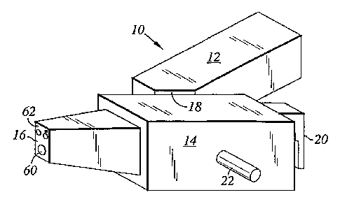
FIG. 1 is a simplified view of the apparatus in accordance with the present
invention;
FIG. 2 is a top plan view of the apparatus of FIG. 1;
FIG. 3 is a perspective view of the emitter housing illustrating the mounting
face;
FIG. 4 is view of the side wall of the marking head, broken away for purposes
of illustration,
showing a cylindrical extension that is joumaled in the mounting face of the
emitter housing of FIG.
3;
FIG. 5 is a side sectional elevation of the marking head of FIG. 1;
FIG. 6 is a top sectional view in enlarged scale of the emitter housing
partially broken for
compactness of illustration showing the alignment mirror for directing the
laser beam into the
marking head; and
FIG. 7 is a schematic diagram of the system.
Detailed Description of the Invention
The invention is described herein in connection with the inscription of
indicia on vehicle
windows. The apparatus of the present invention, shown generally as 10, is
illustrated in a simplified
perspective view in FIG. 1 and in top plan view in FIG. 2. The apparatus 10
comprises an emitter
housing 12 comprising a housing having top, bottom side and end walls. As
illustrated, a marking
head 14 is pivotally mounted on a side wall of the emitter housing. A laser
source of conventional
design that is capable of emitting a beam to which the surface being etched is
not transparent and
the associated electronics in support thereof are disposed in the emitter
housing 12. The laser and
associated electronics are connected to a suitable power source (not shown).
An eximer or C02 laser
is preferred for use in the present invention because the emission of these
lasers is particularly suited
for etching oxide containing surfaces such as glass, anodized aluminum,
ceramic oxides and the like.
z5 In particular, glass is not transparent to the C02 beam so that the laser
18 is able to etch the glass
surface. The emissions from other types of lasers will not etch glass because
glass is transparent to
CA 02575450 2007-01-26
WO 2006/022653 PCT/US2004/024404
7
the emission beam of such lasers and the beam passes through the glass without
etching the surface.
The marking head 14 may be mounted on the top, bottom or either of the side
walls of the
emitter housing.
In the embodiment illustrated in FIGS. 1, 2 and 3 a portion of one side wall
adjacent the front
wall of the emitter housing 12 defines a mounting face 18 that is biased
forwardly inwardly with
respect to the longitudinal axes of the emitter housing. Thus, the
longitudinal axes of the emitter
housing 12 and the marking head 14 are disposed at an angle to one another so
that when the
marking head is affixed to the mounting face 18 the emitter housing extends
away from the marking
head. In this manner the operator has full access to the control grip 20 and
the emitter housing 12
does not interfere with the operation of the marking head 14. It will be
clear, however, that it is not
critical that the operator be behind the marking head 14 and all that is
necessary is that the operator
be positioned to reach the support handle 22 to position the marking head 14
and the control grip 20
to initiate firing of the laser.
A pivot joint, shown generally as 15, for pivotally mounting the marking head
14 to a wall
of the emitter housing 12 is illustrated in FIG. 3. The joint 15 is formed by
a cylindrical extension
16 from the side wall of the marking head 14 that is journaled in a
corresponding opening 17 in the
wall of the emitter housing 12 on which the marking head 14 is mounted. In the
embodiment
illustrated the pivot joint 15 is located at the mounting face 18. A suitable
bearing assembly (not
shown) of conventional design is located at the wall of the emitter housing to
assist in supporting
the cylindrical extension 16 and to provide easy pivoting of the marking head
14.
A through running passage 24 in the'cylindrical extension is aligned with a
corresponding
passage 26 in the wall of the marking head 14 to define an optical path for
the laser beairi to traverse
from the emitter housing 12 to the beam directing apparatus of the marking
head. As is shown in
FIG. 5, an adjustable alignment mirror 24 is disposed in the emitter housing
12 in the path of the
laser beam to direct it through the optical path in the emitter housing 12,
the pivot joint 15 and the
~
CA 02575450 2007-01-26
WO 2006/022653 PCT/US2004/024404
8
side wall of the marking head 14.
The marking head 14 comprises a housing having top, bottom and side walls. A
front wall
defines an emission face 16 and a rear wall 18. A pistol grip control 20
having a trigger 50 for
initiating the laser etching and firing and a positioning button 52, the
function of which will be
explained below, is affixed to the rear wall 18,. A support handle 22 extends
from the side of the
marking head 14 opposite the side affixed to the emitter housing 12. The
marking head 14 contains
the beam control apparatus that comprises an X and a Y galvos mirror mechanism
32 and 34
respectively. The X galvos 32 includes a motor 36 and a rotatable mirror 38
that is carried by linkage
40 to the motor 36 for rotation about an axis normal to the emission beam as
it is reflected from the
alignment minror 24 through the optical path. The Y galvos 34 similarly
includes a rotatable mirror
38 connected by the linkage 40 to a motor 36 for rotation of the mirror 38
about an axis parallel to
the emission beam as it is reflected from the alignment mirror 24. The Y
galvos 34 also is in
electronic communication with the printed circuitry 44 for positioning the
mirror 38 in response to
the control signals.
The mirror 38 of the X galvos 32 is disposed in the path of the emission beam
of the laser
as it is reflected through the optical path and reflects the emission beam to
the mirror 38 of the Y
galvos 34. The mirror 38 of the Y galvos 34 reflects the beam through the
focusing lens 42 into the
marking head 14. Rotation of the mirror 38 of the X galvos 32 causes the beam
to be moved in an
X direction on the surface being etched and the rotation of the mirror of the
Y galvos 34 moves the
beam in the Y direction. It should be clear that the position of the X galvos
32 and the Y galvos 34
can be reversed so that the emission beam contacts the mirror 38 of the Y
galvos 34 first. To
maintain the focal plane to keep the image in focus and to permit across the
entire field of interest,
it is highly preferred that the lens be a "theta" lens, that is a lens that
provides a flat field and thus
the image remains focused regardless ofwhich portion ofthe lens the emission
beam passes through.
In the embodiment described herein, the focusing lens 39 is formed of a
material transparent to the
C02 laser 18 beam. Germanium is one such material that can be used to with
good results to form
CA 02575450 2007-01-26
WO 2006/022653 PCT/US2004/024404
9
the lens_
A printed circuit board 44 contains suitable circuitry and memorydevices to
receive and store
control signals and to electronically communicate with the X galvos 32 and
Y.galvos 34 to relay
control signals from a system controller for controlling the motors 36 to
position the mirrors 38
responsive to the control signals. The control circuitry includes a suitable
shift register and clock
which operate in a manner well known in the art to receive the signal from the
system controller and
to transmit the signal to the appropriate operating components, i.e., the
laser and the position sensors
of the X galvos 40 and the Y galvos 42. The incoming signal may be in the form
of timed pulses.
The incoming signal thus contains the necessary commands to position the
mirrors for scanning the
.10 beam over the surface being etched and to control the duration of the
emission from the laser.
The front wall of the marking head 14 defines the emission face 16 that
includes a port 60
through which the laser beam exits the marking head 14 and a pair of
interlocks 62, each of which
include a spring loaded pin to break the circuit to the laser and prevent the
laser from firing unless
the pins are fully retracted. A pair of suction cups 64 are carried on the
emission face that
communicate with a suction chamber 66 in the emission housing for drawing the
emission face
against the surface being etched. A vacuum line opens into the suction chamber
66 at 68 for reducing
pressure in the suction chamber. As is most clearly shown in FIG. 7, the
control signals are
generated by a system controller 70, such as a conventional personal computer
or equivalent device,
such as a Motorola 68000 processor, to which data may be input manually by a
conventional
keyboard or by automated systems, such as barcode readers and the like. The
system controller
converts the data input to suitable digital control signal comprising an
address code and command
code for the operational components of the system. The command signals are
output to the circuit
board 44 for storage. The marking head 14 is positioned with the emission face
16 essentially
contiguous to the surface to be etched. The suction cups 64 contact the
surface and, due to suction
from the suction chamber aid in drawing the emission face 16 against the
surface to depress the
interlocks and complete the circuit to the laser. An indicator light (not
shown) on the top wall of the
CA 02575450 2007-01-26
WO 2006/022653 PCT/US2004/024404
marking head 14 flashes to indicate that the laser can be fired. Activation of
the trigger 50 completes
a circuit to the laser for firing and to the circuit board 44 for relaying the
command signals to the
laser to control the duration of emission and to the motors 36 of the X galvos
32 and Y galvos 34
for controllably scanning the laser emission beam over a surface being etched.
In response to the
5 control signal, the C02 laser emits a high intensity light beam to which
glass is opaque. The
emission power of the C02 laser preferably ranges between 20 watts and 25
watts. C021asers in this
power range produce a beam powerful enough to penetrate the glass surface for
etching but not so
deeply to weaken the structural integrity of the glass composition. Thus it is
preferred that the C02
laser have an output on the order of 20-25 watts to generate a beam of
sufficient amplification to
10 overcome interference due to condensation, dust, dirt and the. like, which
may collect on the
reflecting mirrors and lens of the optical system. It will be understood,
however, that laser beam
emissions of greater or lesser wattage can be employed and controlled by speed
of beam scannining
to achieve etching and yet maintain the structural integrity of the glass.
For the purposes of description, operation of the system will be described in
connection with
the etching of a vehicle VIN number on the desired locations on the windshield
and side window and
automobile. The VIN number is input to the system controller via a keyboard or
in the alternative
via a bar code reader which is read a bar code which contains the desired
data. The system controller
converts the input data to a digitized control signal which comprises timed
signal pulses for controll-
ing the laser and the x and y galvos, 32 and 34 respectively, as described
above. For marking VIN
numbers on vehicles the marking head 14 and emitter housing 12 are carried by
supporting apparatus
of the general type described in U.S. patent 5,298,717. A frame including a
track member for lateral
movement and a swing arm support the emitter housing 12 and marking head 14.
The weight of the
emitter housing 12 and marking head 14 are counter balanced by a weight and a
motor powers
movement along the track member. The motor is operated by depressing the
positioning button 52.
The emission housing 12 and marking head 14 assembly is moved to a position
adjacent the
surface to be etched. The marking head 14 is pivoted as necessary to insure
that the emission face
CA 02575450 2007-01-26
WO 2006/022653 PCT/US2004/024404
11
16 is in essentially the same plane as the surface to be etched. The emission
face 16 of the marking
head 27 is placed adjacent the surface to be etched so that the pins of the
interlocks 62 are in contact
with the surface to be etched. The emission face 16 is drawn into contiguity
with the surface being
etched by the suction cups 64 and the pins of the interlocks 62 are retracted
to complete all circuits
to permit operation of the C021aser and to insure that the marking head does
not move during the
etching process.
In addition, retraction of the pins of the interlocks 62 close the circuit
from the circuit board
44 to relay the control signals to activate the galvos motors 36 to locate the
reflecting mirrors 38 of
the X and Y galvos, 32 and 34, in the proper plane to cause the beam to be
scanned across the
surface to be etched in the desired pattern to etch the VIN number in the
glass. When the pattern has
been completed the control signal turns the C021aser 18 off and the emitter
housing 12 and marking
head 14 assembly can be moved for the next etching operation.
From the foregoing it will be seen that the apparatus of the present invention
provides a
quick, safe, and environmentally acceptable method for etching glass which
lends itself to automated
production operations. The power of the C021aser 18 can be readily controlled
to avoid any struc-
tural damage to the surface being etched and the process is relatively fast,
on the order of a few
seconds compared to minutes with the chemical sandblasting techniques.
As will be understood by those skilled in the art, various arrangements other
than those
described in detail in the specification will occur to those persons skilled
in the art, which
arrangements lie within the spirit and scope of the invention. It is therefore
to be understood that the
invention is to be limited only by the claims appended hereto.
Having described the invention, I claim: