Sélection de la langue

Search

Sommaire du brevet 2576423 

Énoncé de désistement de responsabilité concernant l'information provenant de tiers

Une partie des informations de ce site Web a été fournie par des sources externes. Le gouvernement du Canada n'assume aucune responsabilité concernant la précision, l'actualité ou la fiabilité des informations fournies par les sources externes. Les utilisateurs qui désirent employer cette information devraient consulter directement la source des informations. Le contenu fourni par les sources externes n'est pas assujetti aux exigences sur les langues officielles, la protection des renseignements personnels et l'accessibilité.

Disponibilité de l'Abrégé et des Revendications

L'apparition de différences dans le texte et l'image des Revendications et de l'Abrégé dépend du moment auquel le document est publié. Les textes des Revendications et de l'Abrégé sont affichés :

  • lorsque la demande peut être examinée par le public;
  • lorsque le brevet est émis (délivrance).
(12) Demande de brevet: (11) CA 2576423
(54) Titre français: GAINE DE TUBE STERILE
(54) Titre anglais: STERILE TUBING SHEATH
Statut: Réputée abandonnée et au-delà du délai pour le rétablissement - en attente de la réponse à l’avis de communication rejetée
Données bibliographiques
(51) Classification internationale des brevets (CIB):
  • A61B 46/10 (2016.01)
  • A61B 90/40 (2016.01)
  • A61F 09/007 (2006.01)
(72) Inventeurs :
  • MACKOOL, RICHARD J. (Etats-Unis d'Amérique)
(73) Titulaires :
  • ALCON, INC.
(71) Demandeurs :
  • ALCON, INC. (Suisse)
(74) Agent: SMART & BIGGAR LP
(74) Co-agent:
(45) Délivré:
(86) Date de dépôt PCT: 2005-03-08
(87) Mise à la disponibilité du public: 2006-11-10
Requête d'examen: 2007-02-13
Licence disponible: S.O.
Cédé au domaine public: S.O.
(25) Langue des documents déposés: Anglais

Traité de coopération en matière de brevets (PCT): Oui
(86) Numéro de la demande PCT: PCT/US2005/007466
(87) Numéro de publication internationale PCT: US2005007466
(85) Entrée nationale: 2007-02-05

(30) Données de priorité de la demande:
Numéro de la demande Pays / territoire Date
10/825,046 (Etats-Unis d'Amérique) 2004-04-15

Abrégés

Abrégé français

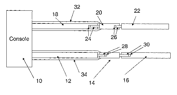
L'invention concerne une gaine souple (32, 34) fixée à une extrémité de tube d'extension (20,14) rigide. L'autre extrémité du tube d'extension rigide est connectée à un instrument manuel chirurgical. Les deux gaines souples peuvent être utilisées - l'une comme barrière contre la contamination d'un tube d'aspiration (18) et l'autre comme barrière contre la contamination d'un tube d'irrigation (12). Lesdites barrières sont constituées par fixation des deux tubes d'extension rigides entre l'instrument chirurgical manuel et un instrument associé aux tubes d'aspiration et d'irrigation. Chaque gaine souple peut se plier ou se déployer de sorte qu'elle peut se déployer à partir d'un état plié sur les tubes d'aspiration ou d'irrigation associés et être fixée à l'état déployé. Les tubes d'aspiration et/ou d'irrigation sont connectés à une cassette de nécessaire chirurgical.


Abrégé anglais


A flexible sheath (32, 34) is attached to an end of a rigid extension tube
(20,14). The other end of the rigid extension tube is connected with a
surgical handpiece. Two flexible sheaths may be used - one as a barrier
against contamination of aspiration tubing (18) and the other as a barrier
against contamination of irrigation tubing (12). This is effected by securing
two rigid extension tubes between the surgical handpiece and an associated one
of the aspiration and irrigation tubings. Each flexible sheath is collapsible
and expandable so they may be expanded from a collapsed condition over the
associated aspiration or irrigation tubings and secured in the expanded
condition. The aspiration and/or irrigation tubings are connected to a
cassette of a surgical pack.

Revendications

Note : Les revendications sont présentées dans la langue officielle dans laquelle elles ont été soumises.


6
WHAT IS CLAIMED IS
1. A sterilized barrier apparatus characterized by
a sterile, tubular sheath that is collapsible into a collapsed condition
and expandable from the collapsed condition into an expanded condition;
a hollow extension tube secured to a distal end of the sterile, tubular
sheath; and
an aspiration tube having a distal end to which is attached the hollow
extension tube, the sterile, tubular sheath being secured to the aspiration
tube
at a location spaced from the distal end of the aspiration tube and being in
the
expanded condition.
2. A sterilized barrier apparatus of claim 1, further characterized by
a surgical pack that includes the aspiration tube, the surgical pack including
a
cassette arranged to receive contents of the aspiration tube that are being
aspirated, the aspiration tube having a proximal end closer to the cassette
than the distal end of the aspiration tube, the location where the sterile,
tubular sheath is secured to the aspiration tube being closer to the proximal
E)nd than to the distal end of the aspiration tube.
3. A sterilized barrier apparatus of claim 2, further characterized by
an instrument console with suction pump that, when activated, suctions the
aspiration tube, the aspiration tube projecting from the instrument console.
4. A sterilized barrier apparatus of claim 1, further characterized by
3. surgical handpiece attached to the distal end of the aspiration tube.
5. A sterilized barrier apparatus of claim 1, characterized in that the
surgical handpiece is attached to a distal end of the hollow, extension tube.
6. A method of forming a sterilized barrier, characterized by:

7
attaching a hollow extension tube to a distal end of an aspiration tube;
pulling a proximal end of a sterile, tubular sheath over and along the
aspiration tube to expand the sterile tubular sheath from a collapsed
condition
into an expanded condition, a proximal end of the hollow extension tube being
secured to the sterile, tubular sheath; and
securing the proximal end of the sterile, tubular sheath to the
aspiration tube at a location spaced from the distal end of the aspiration
tube,
thereby forming a sterilized barrier.
7. A method of claim 6, further characterized by aspirating
atmospheric air through the aspiration tube.
8. A method of claim 6, further characterized by aspirating fluid
within a sterilized container through the aspiration tube.

8
CLAIMS
WHAT IS CLAIMED IS:
1. A sterilized barrier apparatus characterized by
a sterile, tubular sheath that is collapsible into a collapsed condition
and expandable from the collapsed condition into an expanded condition, the
sterile tubular sheath having a shorter length in the collapsed condition than
in
the expanded condition;
a hollow extension tube secured to a distal end of the sterile, tubular
sheath; and
an aspiration tube having a distal end to which is attached the hollow
extension tube, the sterile, tubular sheath having a proximal end arranged to
be secured to a port of an instrument console or to the aspiration tube at a
location spaced from the distal end of the aspiration tube while in the
expanded condition.
2. A sterilized barrier apparatus of claim 1, further characterized by
a surgical pack that includes the aspiration tube, the surgical pack including
a
cassette arranged to receive contents of the aspiration tube that are being
aspirated, the aspiration tube having a proximal end closer to the cassette
than the distal end of the aspiration tube, the location where the sterile,
tubular sheath is secured to the aspiration tube being closer to the proximal
end than to the distal end of the aspiration tube.
3. A sterilized barrier apparatus of claim 2, further characterized by
an instrument console with suction pump that, when activated, suctions the
aspiration tube, the aspiration tube projecting from the instrument console.
4. A sterilized barrier apparatus of claim 1, 2 or 3, characterized in
that a surgical handpiece is attached to a distal end of the hollow, extension
tube.
5. A method of forming a sterilized barrier, characterized by:
attaching a hollow extension tube to a distal end of an aspiration tube;

9
pulling a proximal end of a sterile, tubular sheath over and along the
aspiration tube to expand the sterile tubular sheath from a collapsed
condition
into an expanded condition, a proximal end of the hollow extension tube being
secured to the sterile, tubular sheath, the sterile, tubular sheath being
longer
in the expanded condition than in the collapsed condition; and
arranging the proximal end of the sterile, tubular sheath into position to
be secured to a port of an instrument console or to the aspiration tube at a
location spaced from the distal end of the aspiration tube, thereby forming a
sterilized barrier.
6. A method of claim 5, further characterized by aspirating
atmospheric air through the aspiration tube.
7. A method of claim 5, further characterized by aspirating fluid
within a sterilized container through the aspiration tube.
8. A method of claim 5, further characterized by including the
aspiration tube and a cassette as part of a surgical pack, arranging the
cassette to receive contents of the aspiration tube that are being aspirated,
the aspiration tube having a proximal end closer to the cassette than the
distal
end of the aspiration tube, the location where the sterile, tubular sheath is
secured to the aspiration tube being closer to the proximal end than to the
distal end of the aspiration tube.
9. A method of claim 8, further characterized by an instrument
console with suction pump that, when activated, suctions the aspiration tube,
the aspiration tube projecting from the instrument console.
10. A method of claim 5, 6, 7, 8 or 9, characterized by attaching a
surgical handpiece to a distal end of the hollow, extension tube.

Description

Note : Les descriptions sont présentées dans la langue officielle dans laquelle elles ont été soumises.


CA 02576423 2007-02-05
WO 2005/104979 PCT/US2005/007466
1
STERILE TUBING SHEATH
BACKGROUND OF THE INVENTION
[0001] The present invention relates to a sterile tubing sheath as
part of a sterilized barrier apparatus and to a method of forming a sterilized
barrier where an aspiration tube is used with a surgical handpiece in ocular
surgery procedures.
DISCIJSSION OF RELATED ART
[0002] During various types of surgical procedures, one or more
sterile, hollow tubings may be used to transport fluid to the eye and to
transport fluid, tissue, blood, etc. from the eye. Such surgical procedures
are
exemplified by certain ocular procedures such as cataract removal and
vitrectomy operations.
[0003] Such sterile, hollow tubings are typically sold in
combination with a "cassette", which is a collection vehicle into which the
removed fluid, tissue, etc. is deposited. Alcon Laboratories, Inc., Alcon
Universal Ltd, Alcon Surgical, Inc., Alcon Manufacturing, Ltd. or Alcon, Inc.
is
a supplier of such a cassette.
[0004] The combination of one or more sterile, hollow tubings
and the cassette is typically referred to as a surgical pack. The surgical
pack
can be expensive and requires a certain amount of time to install in an
instrument used for the accomplishment of the desired surgical procedure
[0005] The external surface of the hollow tubings may become
contaminated from handling or from exposure to the patient during the
surgical operation. Currently, these surgical packs are generally used only
once and then disposed, which is obviously wasteful of the surgical packs.
Occasionally, the tubing is removed, cleaned and sterilized and then re-used.
However, such removing, cleaning and sterilizing procedures are labor
intensive of staff time and costly as concerns use of the sterilizing agents.
Such procedures result in a relatively inefficient use of staff time and
create

CA 02576423 2007-02-05
WO 2005/104979 PCT/US2005/007466
2
downtime in use of the surgical packs and thus inefficient use of them until
the
sterilizing process is over and the packs are once again installed into
position.
'[0006] It would be desirable to re-use the surgical packs safely
for operations involving different patients without introducing a risk of
contamination to any of the patients.
BRIEF SUMMARY OF THE INVENTION
[0007] One aspect of the invention resides in a sterilized barrier
and method of forming a sterilized barrier for an aspiration tubing and an
irrigation (infusion) tubing to a surgical handpiece.
BRIEF DESCRIPTION OF THE DRAWINGS
[0008] For a better understanding of the present invention,
reference is made to the following description and accompanying drawings,
while the scope of the invention is set forth in the appended claims.
[0009] Figure 1 is a schematic representation of a surgical pack
employing a sheath of the present invention, with the sheath shown in an
expanded condition.
[0010] Figure 2 is a schematic representation of the sheaths and
rigid extension tubes of Figure 1 but in a collapsed condition.
DETAILED DESCRIPTION OF THE INVENTION
[0011] An intent of the invention is that after completion of a
surgical procedure, tubings, cassette, etc. are left in place. That is, they
are
permitted to remain attached to the instrument console 10 (Fig. 1).
[0012] As shown in Fig. 1, an infusion or irrigation tubing 12
extends from the console 10. A small extension tube 14 is preferably rigid
and constructed so as to not significantly alter the inner diameter of the
lumen
of the tubing 12. The small extension tube 14 has a proximal end attached to
the distal end of the infusion or irrigation tubing 12 using conventional
sterile

CA 02576423 2007-02-05
WO 2005/104979 PCT/US2005/007466
3
technique. The distal end of the small extension tube 14 is in turn connected
to a metallic tubing 16 of a surgical handpiece.
[0013] An aspiration tubing 18 extends from the console 10. A
further small extension tube 20, which is also preferably rigid, is
constructed
as well so as to not to significantly alter the inner diameter of the lumen of
the
aspiration tubing 18, and is likewise attached using conventional sterile
technique. The further small extension tube 20 has a proximal end attached
to the distal end of the aspiration tubing 18. The distal end of the further
small
extension tube 20 is in turn connected to a further metallic tubing 22 of the
surgical handpiece.
[0014] Male and female connectors 24 engage each other in a
mating manner to connect the aspiration tubing 18 and the further small
extension tube 20 together. Male and female connectors 26 engage each
other in a mating manner to connect the further small extension tube 20 with
the metallic tubing 22. Also, male and female connectors 28 engage each
other in a mating manner to connect the irrigation tubing 12 to the small
extension tube 14. Male and female connectors 30 engage each other in a
mating manner to connect the small extension tube 14 to the metallic tubing
16. Fig. 1 shows the connectors 28, 30 almost fully mated. Once fully mated,
the connectors 28, 30 may have their surfaces configured to engage each
other in a manner that retains their mated state to avoid inadvertent
separation.
[0015] The small extension tube 14 and the further small
extension tube 20 may each be a rigid tubing attachment that has attached to
it in any conventional manner, such as with an adhesive, a respective, soft
sheath 32, 34. The sheaths 32, 24 may be pre-rolled or collapsed in
accordion fashion (Fig. 2) and expandable to form a structure that may be
symmetric, such as tubular (Fig. 1). Each sheath 32, 34 is hollow and open at
one end to enable being pulled over the associated (irrigation or aspiration)
tubing as applicable and toward the surgical instrument console. The open
end of the sheath 32, 24 is then attached either to a port of the console or
to

CA 02576423 2007-02-05
WO 2005/104979 PCT/US2005/007466
4
an end of the associated tubing in relative close proximity to the port. The
attachment of the sheath 32, 34 to the port or to the end of the associated
tubing may be effected in any conventional manner, such as with an
adhesive. The sheaths each present a completely sterile external surface
placed over the tubing to serve a sterilized barrier.
[0016] Typically,,there are two tubings attached to the console,
i.e., the irrigation tubing 12 and the aspiration tubing 18. The distal end of
each of these tubings differ from each other in configuration to avoid
confusion (one is male and the other is female). In accordance with the
invention, each of these distal 'ends is attached to its own small extension
tube, which in turn is attached to a respective metallic tubing 16, 22 of the
sterilized surgical handpiece. The handpiece may be an ultrasonic
instrument, cutting instrument, illuminated irrigating instrument, etc.
[0017] The aspiration tubing 18, which is tubing that leaves the
surgical site, could be subjected to a sterilization procedure by internally
irrigating prior to the application of the sheath 32. This could be done by
the
inserting the aspiration tubing into a sterile container of preparatory fluid,
which is then aspirated to remove fluid within it that remained from the
previous surgical procedure. Alternatively, at the conclusion of the previous
surgical procedure, the instrument's pump could be permitted to run with the
surgical instrument in atmospheric air. Fluid within the aspiration tubing
would
thereby be completely removed prior to attachment of the sterile extension
and surrounding sheath.
[0018] The irrigation tubing 12, which is tubing that is used to
deliver fluid to the eye, does not need to be cleared of fluid because its
contents are sterile and have not entered a surgical field. However, after
each use, this tubing could be cleared of fluid by simple gravitational flow
if
desired.
[0019] Conventionally, as soon as the aspiration or irrigation
tubing is exposed to a patient or a gloved hands of a technician or surgeon,

CA 02576423 2007-02-05
WO 2005/104979 PCT/US2005/007466
such tubing is considered to be contaminated and thus could not be re-used
during a subsequent operation without proper sterilization.
[0020] In accordance with the intention, however, only the
sheaths and the small extension tubes would become contaminated upon
exposure to the patient or the gloved hands of the technician or surgeon.
Thus, only the sheaths and the small extension tubes would need to be
discarded after each surgical procedure. The aspiration and irrigation tubings
that are shrouded by the sheaths and the cassette to which the tubings are
attached would not need to be discarded but rather could be reused, after
implementing the previously mentioned sterilization technique on the
aspiration tubing and possibly allowing for gravitational flow for the
irrigation
tubing.
[0021] While the foregoing description and drawings represent
embodinients of the present invention, it will be understood that various
changes and modifications may be made without departing from the scope of
the present invention.

Dessin représentatif
Une figure unique qui représente un dessin illustrant l'invention.
États administratifs

2024-08-01 : Dans le cadre de la transition vers les Brevets de nouvelle génération (BNG), la base de données sur les brevets canadiens (BDBC) contient désormais un Historique d'événement plus détaillé, qui reproduit le Journal des événements de notre nouvelle solution interne.

Veuillez noter que les événements débutant par « Inactive : » se réfèrent à des événements qui ne sont plus utilisés dans notre nouvelle solution interne.

Pour une meilleure compréhension de l'état de la demande ou brevet qui figure sur cette page, la rubrique Mise en garde , et les descriptions de Brevet , Historique d'événement , Taxes périodiques et Historique des paiements devraient être consultées.

Historique d'événement

Description Date
Inactive : CIB désactivée 2018-01-20
Inactive : CIB en 1re position 2017-11-21
Inactive : CIB attribuée 2017-11-21
Inactive : CIB expirée 2016-01-01
Le délai pour l'annulation est expiré 2009-03-09
Demande non rétablie avant l'échéance 2009-03-09
Inactive : Abandon. - Aucune rép. à lettre officielle 2008-08-05
Inactive : Lettre officielle 2008-05-05
Réputée abandonnée - omission de répondre à un avis sur les taxes pour le maintien en état 2008-03-10
Lettre envoyée 2007-05-09
Inactive : Page couverture publiée 2007-04-20
Inactive : Lettre de courtoisie - Preuve 2007-04-10
Inactive : Notice - Entrée phase nat. - Pas de RE 2007-04-04
Demande reçue - PCT 2007-03-01
Toutes les exigences pour l'examen - jugée conforme 2007-02-13
Exigences pour une requête d'examen - jugée conforme 2007-02-13
Requête d'examen reçue 2007-02-13
Exigences pour l'entrée dans la phase nationale - jugée conforme 2007-02-05
Demande publiée (accessible au public) 2006-11-10

Historique d'abandonnement

Date d'abandonnement Raison Date de rétablissement
2008-03-10

Taxes périodiques

Le dernier paiement a été reçu le 2007-02-05

Avis : Si le paiement en totalité n'a pas été reçu au plus tard à la date indiquée, une taxe supplémentaire peut être imposée, soit une des taxes suivantes :

  • taxe de rétablissement ;
  • taxe pour paiement en souffrance ; ou
  • taxe additionnelle pour le renversement d'une péremption réputée.

Les taxes sur les brevets sont ajustées au 1er janvier de chaque année. Les montants ci-dessus sont les montants actuels s'ils sont reçus au plus tard le 31 décembre de l'année en cours.
Veuillez vous référer à la page web des taxes sur les brevets de l'OPIC pour voir tous les montants actuels des taxes.

Historique des taxes

Type de taxes Anniversaire Échéance Date payée
TM (demande, 2e anniv.) - générale 02 2007-03-08 2007-02-05
Rétablissement (phase nationale) 2007-02-05
Taxe nationale de base - générale 2007-02-05
Requête d'examen - générale 2007-02-13
Titulaires au dossier

Les titulaires actuels et antérieures au dossier sont affichés en ordre alphabétique.

Titulaires actuels au dossier
ALCON, INC.
Titulaires antérieures au dossier
RICHARD J. MACKOOL
Les propriétaires antérieurs qui ne figurent pas dans la liste des « Propriétaires au dossier » apparaîtront dans d'autres documents au dossier.
Documents

Pour visionner les fichiers sélectionnés, entrer le code reCAPTCHA :


Pour visualiser une image, cliquer sur un lien dans la colonne description du document. Pour télécharger l'image (les images), cliquer l'une ou plusieurs cases à cocher dans la première colonne et ensuite cliquer sur le bouton "Télécharger sélection en format PDF (archive Zip)" ou le bouton "Télécharger sélection (en un fichier PDF fusionné)".

Liste des documents de brevet publiés et non publiés sur la BDBC .

Si vous avez des difficultés à accéder au contenu, veuillez communiquer avec le Centre de services à la clientèle au 1-866-997-1936, ou envoyer un courriel au Centre de service à la clientèle de l'OPIC.


Description du
Document 
Date
(aaaa-mm-jj) 
Nombre de pages   Taille de l'image (Ko) 
Description 2007-02-04 5 230
Dessins 2007-02-04 2 27
Revendications 2007-02-04 4 154
Abrégé 2007-02-04 2 83
Dessin représentatif 2007-02-04 1 7
Revendications 2007-02-05 2 52
Accusé de réception de la requête d'examen 2007-05-08 1 176
Avis d'entree dans la phase nationale 2007-04-03 1 192
Courtoisie - Lettre d'abandon (taxe de maintien en état) 2008-05-04 1 178
Courtoisie - Lettre d'abandon (lettre du bureau) 2008-10-27 1 165
PCT 2007-02-04 21 755
Correspondance 2007-04-03 1 26
Correspondance 2008-05-04 2 35