Sélection de la langue

Search

Sommaire du brevet 2578462 

Énoncé de désistement de responsabilité concernant l'information provenant de tiers

Une partie des informations de ce site Web a été fournie par des sources externes. Le gouvernement du Canada n'assume aucune responsabilité concernant la précision, l'actualité ou la fiabilité des informations fournies par les sources externes. Les utilisateurs qui désirent employer cette information devraient consulter directement la source des informations. Le contenu fourni par les sources externes n'est pas assujetti aux exigences sur les langues officielles, la protection des renseignements personnels et l'accessibilité.

Disponibilité de l'Abrégé et des Revendications

L'apparition de différences dans le texte et l'image des Revendications et de l'Abrégé dépend du moment auquel le document est publié. Les textes des Revendications et de l'Abrégé sont affichés :

  • lorsque la demande peut être examinée par le public;
  • lorsque le brevet est émis (délivrance).
(12) Brevet: (11) CA 2578462
(54) Titre français: SUPPORT CHIRURGICAL POUR FEMUR
(54) Titre anglais: SURGICAL SUPPORT FOR FEMUR
Statut: Accordé et délivré
Données bibliographiques
(51) Classification internationale des brevets (CIB):
  • A61F 5/00 (2006.01)
(72) Inventeurs :
  • MATTA, JOEL (Etats-Unis d'Amérique)
(73) Titulaires :
  • ORTHOPEDICS SYSTEMS, INC.
(71) Demandeurs :
  • ORTHOPEDICS SYSTEMS, INC. (Etats-Unis d'Amérique)
(74) Agent: SMART & BIGGAR LP
(74) Co-agent:
(45) Délivré: 2014-05-06
(86) Date de dépôt PCT: 2005-08-31
(87) Mise à la disponibilité du public: 2006-03-16
Requête d'examen: 2010-08-30
Licence disponible: S.O.
Cédé au domaine public: S.O.
(25) Langue des documents déposés: Anglais

Traité de coopération en matière de brevets (PCT): Oui
(86) Numéro de la demande PCT: PCT/US2005/030737
(87) Numéro de publication internationale PCT: WO 2006028788
(85) Entrée nationale: 2007-02-26

(30) Données de priorité de la demande:
Numéro de la demande Pays / territoire Date
10/930,809 (Etats-Unis d'Amérique) 2004-09-01

Abrégés

Abrégé français

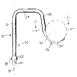
L'invention concerne un support chirurgical pour fémur qui comprend une tige présentant une partie proximale et une partie distale. La tige est située le long d'un axe qui coïncide avec un premier plan. Un crochet est relié à la tige au moyen d'une partie intermédiaire et est situé dans un second plan qui croise le premier plan. Le crochet comprend une partie aplatie conçue pour porter le fémur.


Abrégé anglais


A surgical support for a femur utilizing a shaft having a proximal portion and
a distal portion. The shaft lies along an axis which is coincident with a
first plane. A hook connects to the shaft through an intermediate portion and
lies in a second plane which intersects the first plane. The hook includes a
flattened portion for support of the femur.

Revendications

Note : Les revendications sont présentées dans la langue officielle dans laquelle elles ont été soumises.


CLAIMS:
1. A device intended for directly contacting and
supporting a femur bone within a wound of a subject during a
surgical procedure, the device comprising:
a. a shaft, said shaft possessing a proximal portion,
and distal portion, at least a portion of said shaft lying
along a first axis which coincides with a first plane;
b. a hook, said hook including an end, a portion of
said hook lying along a second axis which coincides with a
second plane, said hook further possessing a free tip
configured and intended to enter the wound of the subject, for
directly contacting the femur; and
c. an intermediate portion connecting said shaft and
said hook, said shaft, said hook and said intermediate portion
forming a one-piece member, said intermediate portion and said
hook lying apart from said first axis of said shaft, said first
and second axes being separated from one another by said
intermediate portion, said first and second planes lying along
said first and second axes, respectively, not being coplanar.
2. The device of claim 1 in which said shaft comprises a
rigid body.
3. The device of claim 1 in which said hook free tip
includes a flattened portion.
4. The device of claim 1 which further includes a base
member, said base member including a bracket having a plurality
of openings spaced from each other along said bracket, each of
said openings accommodating a portion of said shaft.
8

5. The device of claim 4 in which said shaft includes an
end portion configured to fit in any of said spaced openings of
said bracket.
6. The device of claim 4 in which said shaft comprises a
rigid body.
7. The device of claim 4 in which said hook free tip
includes a flattened portion.
9

Description

Note : Les descriptions sont présentées dans la langue officielle dans laquelle elles ont été soumises.


CA 02578462 2007-02-26
WO 2006/028788 PCT/US2005/030737
SURGICAL SUPPORT FOR FEMUR
BACKGROUND OF THE INVENTION
The present invention relates to a novel and useful
surgical support for a femur.
Recent advances in surgery focus on minimally invasive
techniques, which generally, reduce the size of the incision and
eliminate the detachment or severing of muscles.
In this regard, minimally invasive hip replacement
surgery utilizes entry at the anterior of the patient's leg. By
following such approach, the surgeon may accomplish a hip
replacement by utilizing a four inch incision rather than a ten
inch incision in the prior technique. Also, muscles within the
leg are not damaged, resulting in fast recovery of the patient and
eliminating muscle detachment during the post operative time.
Anterior approach hip replacement techniques still
require access to the acetabulum which must be cleared prior to
the insertion of the artificial femur head. In addition, proper
manipulation and positioning of the femur is essential in carrying
out the anterior approach hip replacement surgery.
A support for a femur during surgical techniques such
as hip replacement would be a notable advance in the medical
field.
1

CA 02578462 2013-01-29
25785-143
BRIEF SUMMARY OF THE INVENTION
In accordance with an embodiment of the present
invention there may be provided a novel and useful support for
a femur during surgical procedures.
The support of an embodiment of the present invention
utilizes a shaft possessing a proximal portion and a distal
portion. At least a part of the shaft lies along an axis which
coincides with a first plane. The shaft may terminate in an
end fitting which allows the shaft to be mounted on a jack
associated with a surgical table.
A hook is also employed in an embodiment of the
present invention and lies in a second plane. The first and
second planes intersect one another. That is to say, the hook
is connected to the shaft by an intermediate portion and is
angulated to properly position the femur and allow the surgeon
to effect hip replacement without the femur obstructing access
to the acetabulum of the hip. Hooks may be oppositely angled
relative to the shaft to accommodate the right or left femur of
a patient.
A base member is also employed for positioning the
shaft relative to the surgical table. The base member may be
fastened to the table or separately supported. In certain
aspects of the present invention the base member may take the
form of a bracket having a plurality of openings. Each opening
in the bracket is capable of accommodating a portion of the
shaft, namely the end portion of the shaft in most cases. The
base member may be connected to a jack associated with the
surgical table.
2

CA 02578462 2013 -11- JA
25785-143
It may be apparent that an embodiment of the
invention may provide a novel and useful support for a femur
bone during a surgical procedure.
An embodiment of the present invention may provide a
support for a femur bone during a surgical procedure which
adequately supports the femur and provides the surgeon with
access to anatomical portions of the hip in order to effect
artificial hip replacement.
An embodiment of the present invention may provide a
support for a femur bone during a surgical procedure which is
compatible with surgical tables used in surgery.
An embodiment of the present invention may provide a
support for a femur bone during a surgical procedure which
allows the practicing of non-invasive hip replacement surgery
and permits fast recovery of patients having such surgery.
An embodiment of the present invention may provide a
support for a femur bone during a surgical procedure which
supports the femur and which is adjustable in conjunction with
a bracket as well as other components found on conventional
surgical tables.
An embodiment of the present invention may provide a
support for a femur bone during a surgical procedure which is
easily engageable with the femur and disengagable when not
required during the surgical procedure.
An embodiment disclosed herein relates to a device
intended for directly contacting and supporting a femur bone
within a wound of a subject during a surgical procedure, the
device comprising: a. a shaft, said shaft possessing a
3

CA 02578462 2013-11-14
25785-143
proximal portion, and distal portion, at least a portion of
said shaft lying along a first axis which coincides with a
first plane; b. a hook, said hook including an end, a portion
of said hook lying along a second axis which coincides with a
second plane, said hook further possessing a free tip
configured and intended to enter the wound of the subject, for
directly contacting the femur; and c. an intermediate portion
connecting said shaft and said hook, said shaft, said hook and
said intermediate portion forming a one-piece member, said
intermediate portion and said hook lying apart from said first
axis of said shaft, said first and second axes being separated
from one another by said intermediate portion, said first and
second planes lying along said first and second axes,
respectively, not being coplanar.
The invention may possess objects and advantages
especially as concerns particular characteristics and features
thereof which will become apparent as the specification
continues.
3a

CA 02578462 2007-02-26
WO 2006/028788
PCT/US2005/030737
BRIEF' DE SCRIPtION ."or HE SEVERAL VIEWS OF THE DRAWING
Fig. 1 is a side elevational view of the support of the
present invention showing a femur in phantom.
Fig. 2 is a front elevational view of a left handed
support for a left leg of the present invention with a femur
depicted in phantom.
Fig. 3 is a sectional view taken along line 3-3 of Fig.
1.
Fig. 4 is a rear elevational view of a right handed
support for a right leg of the present invention located in a
bracket connected to a jack, partially shown.
Fig. 5 is a partial sectional view taken along line 5-5
of Fig. 4.
Fig. 6 is a schematic view indicating the positioning
of the support of the present invention using a right-handed hook
with a conventional surgical table partially depicted, with a
patient in the supine position prior to hip replacement surgery.
For a better understanding of the invention reference
is made to the following detailed description of the preferred
embodiments thereof which should be referenced to the prior
described drawings.
4

CA 02578462 2007-02-26
WO 2006/028788 PCT/US2005/030737
DETAILED DESCRIPTION OF THE PREFERRED EMBODIMENTS OF THE INVENTION
Various aspects of the present invention will evolve
from the following detailed description of the preferred
embodiments thereof which should be referenced to the hereinbefore
delineated drawings.
The preferred embodiment of the invention is depicted
as a whole in the drawings by reference character 10. With
reference to Figs. 1-3, support 10 includes as one of its elements
a shaft 12. Shaft 12 possesses a proximal portion 14 and a distal
portion 16. Shaft 12, or at least a portion of shaft 12, lies
along axis 18. Shaft 12 may be folmed of any rigid material such
as metal, composites, and the like. Distal portion 14 of shaft 12
includes a rectangular solid end 20 and a cap 22, the purpose of
which will be discussed hereinafter.
The proximal portion 16 of shaft 12 leads to an
intermediate or spanning portion 24 and is formed of the same
material as shaft 12. Intermediate portion 24 terminates in a
rounded hook 26 a left-handed version. It should be realized that
hook 26 may be squared or otherwise angulated. Hook 26 is formed
with a tubular end 28 and a flattened curved section 30. Femur 32
is depicted in Figs. 1 and 2 as lying within the flattened portion
30 of hook 26.
Referring now to Fig. 4, it may be observed that
support 10, having a right-handed hook 33 holding left femur 35 is
also provided with a base member 34. Base member 34 may take the
form of a bracket 36 which includes and end portion 38 that
connects to a jack 40 which is part of a conventional surgical
table 42 shown in Fig. 6. With reference to Fig. 5, it may be
apparent that bracket 36 includes a plurality of opening 44 each
of which is intended to fit rectangular solid end 20 of support
shaft 12. Cap 22 serves to limit the penetration of rectangular
solid end 20 of shaft 12 into any one of the plurality of openings
44 of bracket 46. It should be noted that end 20 of bracket 12
lies in opening 46 within bracket 36. With reference to Figs. 2
and 4, it should be seen that hooks 26 and 33 lie along an axes 48

CA 02578462 2007-02-26
WO 2006/028788
PCT/US2005/030737
and 49, respectively, whnfi are not parallel or coincident with
axis 18. In fact, axis 18 lies in a plane 50, while axes 48 and 49
lie in planes 52 and 53. Planes 50 and 52, and planes 50 and 53,
intersect one another. Such angular orientation between hooks 26
or 33 and shaft 12 provides the proper angle to left femurs 32 and
right femur 35, respectively, which is supported by hooks 26 or 33
during hip surgery.
With reference to Fig. 6, anesthetized patient 54 is
shown in place on surgical table 42 a position ready for anterior
approach hip surgery on the hip associated with right leg 56.
Traction boots 58 and 60 are employed and are used to provide
traction through a mechanism of table 42, not shown completely in
Fig. 6. In this regard, a surgical table known as the PRO fx
manufactured by Orthopedic Systems, Inc. of Union City, California
would suffice in this regard. Surgical table jack 40 is able to
raise and lower support 10 connected to bracket 36. The raising
and lowering of jack 40 takes place through a rotatable shaft 62,
partially shown, the motion of which is indicated by directional
arrow 64. Bracket 36 is also capable of rotating relative to jack
40 such that the surgeon performing non-invasive hip surgery
possesses complete control of the positioning of support 10
relative to femur 35, shown in phantom on Figs. 1-4, within right
leg 56.
In operation, the user places support 10 on base member
34 in the form of bracket 36 in the preferred embodiment. Such
mounting is accomplished by the placement of end 20 of shaft 12 of
support 10 within any of the plurality of openings 44 of bracket
36. At the proper time after an incision is made in patient 54,
Fig. 6, hook 26 or 33 enters the wound at the hip region of
patient 54 and supports right femur 32 or left femur 35,
respectively. Typical jack 40, in combination with support 10, is
able to properly angle and support left femur 35 such that the
surgeon is capable of gaining unrestricted access to the
acetabulum and other portions of the hip in order to accomplish an
artificial hip replacement for a patient 54, Fig. 4. When support
6

CA 02578462 2007-02-26
WO 2006/028788
PCT/US2005/030737
is no longer needed, support 10, including hook 26 or 33, is
swing from the wound in patient 54 and moved outwardly by the
rotation of bracket 36 relative to typical jack 40, directional
arrow 66. Support 10 may then be removed or left in this position
as surgery progresses and is finished.
While in the foregoing, embodiments of the present
invention have been set forth in considerable detail for the
purposes of making a complete disclosure of the invention, it may
be apparent to those of skill in the art that numerous changes may
be made in such detail without departing from the spirit and
principles of the invention.
7

Dessin représentatif
Une figure unique qui représente un dessin illustrant l'invention.
États administratifs

2024-08-01 : Dans le cadre de la transition vers les Brevets de nouvelle génération (BNG), la base de données sur les brevets canadiens (BDBC) contient désormais un Historique d'événement plus détaillé, qui reproduit le Journal des événements de notre nouvelle solution interne.

Veuillez noter que les événements débutant par « Inactive : » se réfèrent à des événements qui ne sont plus utilisés dans notre nouvelle solution interne.

Pour une meilleure compréhension de l'état de la demande ou brevet qui figure sur cette page, la rubrique Mise en garde , et les descriptions de Brevet , Historique d'événement , Taxes périodiques et Historique des paiements devraient être consultées.

Historique d'événement

Description Date
Paiement d'une taxe pour le maintien en état jugé conforme 2024-07-26
Requête visant le maintien en état reçue 2024-07-26
Représentant commun nommé 2019-10-30
Requête visant le maintien en état reçue 2018-06-04
Requête pour le changement d'adresse ou de mode de correspondance reçue 2018-03-28
Requête visant le maintien en état reçue 2017-08-29
Requête visant le maintien en état reçue 2016-08-25
Requête visant le maintien en état reçue 2015-08-31
Requête visant le maintien en état reçue 2014-09-02
Accordé par délivrance 2014-05-06
Inactive : Page couverture publiée 2014-05-05
Préoctroi 2014-02-24
Inactive : Taxe finale reçue 2014-02-24
Un avis d'acceptation est envoyé 2013-12-02
Lettre envoyée 2013-12-02
Un avis d'acceptation est envoyé 2013-12-02
Inactive : Q2 réussi 2013-11-28
Inactive : Approuvée aux fins d'acceptation (AFA) 2013-11-28
Modification reçue - modification volontaire 2013-11-14
Requête visant le maintien en état reçue 2013-08-28
Inactive : Dem. de l'examinateur par.30(2) Règles 2013-05-14
Modification reçue - modification volontaire 2013-01-29
Inactive : Dem. de l'examinateur par.30(2) Règles 2012-07-31
Lettre envoyée 2010-09-08
Exigences pour une requête d'examen - jugée conforme 2010-08-30
Toutes les exigences pour l'examen - jugée conforme 2010-08-30
Requête d'examen reçue 2010-08-30
Inactive : Supprimer l'abandon 2009-01-28
Lettre envoyée 2008-10-10
Lettre envoyée 2008-09-15
Exigences de rétablissement - réputé conforme pour tous les motifs d'abandon 2008-08-29
Inactive : Abandon. - Aucune rép. à lettre officielle 2008-08-14
Inactive : Transfert individuel 2008-07-28
Inactive : Lettre officielle 2008-05-14
Inactive : IPRP reçu 2008-02-21
Inactive : Supprimer l'abandon 2007-11-28
Inactive : Abandon. - Aucune rép. à lettre officielle 2007-09-04
Inactive : Correspondance - Formalités 2007-09-04
Réputée abandonnée - omission de répondre à un avis sur les taxes pour le maintien en état 2007-08-31
Inactive : Page couverture publiée 2007-05-10
Inactive : Lettre pour demande PCT incomplète 2007-05-02
Inactive : Notice - Entrée phase nat. - Pas de RE 2007-04-25
Demande reçue - PCT 2007-03-15
Exigences pour l'entrée dans la phase nationale - jugée conforme 2007-02-26
Demande publiée (accessible au public) 2006-03-16

Historique d'abandonnement

Date d'abandonnement Raison Date de rétablissement
2007-08-31

Taxes périodiques

Le dernier paiement a été reçu le 2013-08-28

Avis : Si le paiement en totalité n'a pas été reçu au plus tard à la date indiquée, une taxe supplémentaire peut être imposée, soit une des taxes suivantes :

  • taxe de rétablissement ;
  • taxe pour paiement en souffrance ; ou
  • taxe additionnelle pour le renversement d'une péremption réputée.

Veuillez vous référer à la page web des taxes sur les brevets de l'OPIC pour voir tous les montants actuels des taxes.

Titulaires au dossier

Les titulaires actuels et antérieures au dossier sont affichés en ordre alphabétique.

Titulaires actuels au dossier
ORTHOPEDICS SYSTEMS, INC.
Titulaires antérieures au dossier
JOEL MATTA
Les propriétaires antérieurs qui ne figurent pas dans la liste des « Propriétaires au dossier » apparaîtront dans d'autres documents au dossier.
Documents

Pour visionner les fichiers sélectionnés, entrer le code reCAPTCHA :


Pour visualiser une image, cliquer sur un lien dans la colonne description du document. Pour télécharger l'image (les images), cliquer l'une ou plusieurs cases à cocher dans la première colonne et ensuite cliquer sur le bouton "Télécharger sélection en format PDF (archive Zip)" ou le bouton "Télécharger sélection (en un fichier PDF fusionné)".

Liste des documents de brevet publiés et non publiés sur la BDBC .

Si vous avez des difficultés à accéder au contenu, veuillez communiquer avec le Centre de services à la clientèle au 1-866-997-1936, ou envoyer un courriel au Centre de service à la clientèle de l'OPIC.


Description du
Document 
Date
(aaaa-mm-jj) 
Nombre de pages   Taille de l'image (Ko) 
Description 2007-02-26 7 261
Dessins 2007-02-26 3 66
Revendications 2007-02-26 1 36
Abrégé 2007-02-26 1 56
Dessin représentatif 2007-05-09 1 7
Page couverture 2007-05-10 1 34
Description 2013-01-29 8 282
Revendications 2013-01-29 2 40
Description 2013-11-14 8 284
Revendications 2013-11-14 2 43
Page couverture 2014-04-04 1 34
Confirmation de soumission électronique 2024-07-26 3 74
Rappel de taxe de maintien due 2007-05-01 1 109
Avis d'entree dans la phase nationale 2007-04-25 1 192
Courtoisie - Lettre d'abandon (taxe de maintien en état) 2007-10-29 1 173
Avis de retablissement 2008-09-15 1 164
Courtoisie - Certificat d'enregistrement (document(s) connexe(s)) 2008-10-10 1 104
Rappel - requête d'examen 2010-05-03 1 119
Accusé de réception de la requête d'examen 2010-09-08 1 179
Avis du commissaire - Demande jugée acceptable 2013-12-02 1 162
PCT 2007-02-26 1 23
Correspondance 2007-04-25 1 25
Correspondance 2007-09-04 1 41
PCT 2007-02-27 4 191
Correspondance 2008-05-14 2 35
Taxes 2008-08-29 2 61
Taxes 2011-08-30 1 64
Taxes 2012-08-28 1 65
Taxes 2013-08-28 2 74
Correspondance 2014-02-24 2 74
Taxes 2014-09-02 2 81
Paiement de taxe périodique 2015-08-31 2 81
Paiement de taxe périodique 2016-08-25 2 82
Paiement de taxe périodique 2017-08-29 2 85
Paiement de taxe périodique 2018-06-04 1 59