Note : Les descriptions sont présentées dans la langue officielle dans laquelle elles ont été soumises.
CA 02579792 2007-03-08
WO 2006/029500 PCT/CA2005/001246
SCREEN ASSEMBLY
FIELD OF THE INVENTION
[0001] The present invention relates in general to screens for projecting
images onto and in
particular, the present invention relates to portable screens that are easily
opened for projection
of images onto and closed for storage or transport.
BACKGROUND OF THE INVENTION
[0002] Screens are widely used in homes and in offices for displaying movies,
television
programs, computer displays or the like, from projectors. There are many
different types of
screen assemblies that are commonly used in both homes and in offices for
housing such
screens. Wall mounted screens are convenient as a wall provides a stable and
flat surface on
which to mount the screen. Ceiling mounted screens are also convenient as the
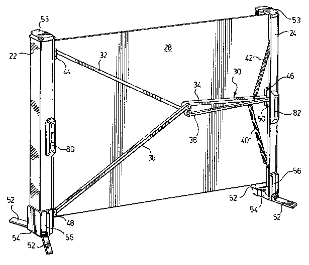
screen is
opened by extending the screen downwardly for use and the screen is closed by
retracting the
screen into a housing mounted to the ceiling. The ceiling mounted housing
provides a
convenient storage location that can be hidden from view. Both wall and
ceiling mounted
housings are inconvenient for movement of the screen to other locations. Such
screens are not
intended to be portable for movement throughout a house, an office, between
offices, etc.
[0003] Portable screen assemblies have found use as portability of screens is
useful for
changing venues in which the screen is used. One example of such a screen is
the large
screen on a tripod stand that has commonly been used for projecting, for
example, slides from a
slide projector. Although these screens found extensive use in the past, such
screens are
somewhat awkward to carry and to erect.
[0004] One particular portable screen that has been proposed is disclosed in
United States
Patent No. 6,249,377 to Takamoto et al. This portable screen includes two
frame members that
are generally parallel. One of the frame members houses a spring-biased roll
to which one end
of the screen is attached and the screen is wound onto the roll when in the
closed position. The
other end of the screen is attached to the other frame member and the frame
members are
separated to open the screen. Support bars extend between the frame members to
maintain
the screen in the open position.
1
CA 02579792 2007-03-08
WO 2006/029500 PCT/CA2005/001246
[0005] This screen suffers from some disadvantages, however. In particular,
the edges of
this screen are not well supported and tend to curl. Therefore the screen does
not provide a flat
projection surface for viewing. In instances in which it is desirable to only
partially open the
screen, the tension in the screen is reduced, causing further screen
instability and edge curl.
[0006] It is therefore desirable to provide a portable screen assembly with
improved screen
stability and reduced edge curl.
SUMMARY OF THE INVENTION
[0007] In one aspect of the present invention there is provided a screen
assembly that
includes a first frame member, a second frame member and a spring biased
roller rotatably
mounted in one of the first frame member and the second frame member. A screen
is fixed at
one end to the spring biased roller and is fixed at a second end to an other
of the first frame
member and the second frame member. An extendable linkage assembly connects
the first
frame member to the second frame member. The extendable linkage assembly
includes a first
arm hingedly connected the first frame member, at a point offset from a center
thereof, a second
arm hingedly connected to the first arm and hingedly connected to the second
frame member,
proximal a center thereof, a third arm hingedly connected to the first frame
member, at a point
on an opposing side of center as the first arm and a fourth arm hingedly
connected to the third
arm and hingedly connected to the second frame member, proximal the center.
The extendable
linkage assembly also includes a first biasing member connected to the second
arm and
connected to the second frame member, at a point offset from the center and a
second biasing
member connected to the fourth arm and connected to the second frame member,
at a point on
an opposing side of the center as the first biasing member. The first and
second frame
members are positionable between a closed position in which the first and
second frame
members are adjacent each other and the screen is rolled on the spring biased
roller, and an
open position in which the first and second frame members are separated and
the screen is at
least partially unrolled from the spring biased roller.
[0008] Advantageously, improved stability of the screen is realized through
the use of the
extendable linkage assembly. Tension is maintained across the screen as the
extendable
linkage assembly is biased to counter the bias of the spring biased roller.
Thus, the spring
biased roller is biased to roll the screen and move the frame members into the
closed position.
2
CA 02579792 2007-03-08
WO 2006/029500 PCT/CA2005/001246
The extendable linkage is biased to counter the bias of the spring biased
roller and maintain the
frame members in an open position. The spring biased roller and the extendable
linkage
assembly reduce screen edge curling and provide a substantially flat
projection surface. Also,
the width of the screen that is used can be adjusted as the separation of the
two frame
members is adjustable and therefore the screen assembly can be used even when
the two
frame members are not in the fully opened position. Improved screen stability
and reduced
screen edge curling is realized even when the frame members are not in the
fully opened
position.
[0009] In one aspect of the present invention, two arms are hingedly connected
to each
frame member for providing stability.
BRIEF DESCRIPTION OF THE DRAWINGS
[0010] Figure 1 is a perspective view of a screen assembly according to an
embodiment of
the present invention, the screen assembly shown in an open position;
[0011] Figure 2 is an alternative perspective view of the screen assembly of
Figure 1, the
screen assembly shown in the open position;
[0012] Figure 3 is a rear view of the screen assembly of Figure 1, shown in
the open position
and in a partially open position in ghost outline.
[0013] Figure 4 is a rear view of the screen assembly of Figure 1, shown in
the partially open
position;
[0014] Figure 5 is a rear view of the screen assembly of Figure 1, shown in
the closed
position;
[0015] Figure 6 is a perspective view of the screen assembly of Figure 1,
shown in the closed
position and with feet of the screen assembly shown in an open position;
[0016] Figure 7 is a perspective view of a portion of the screen assembly of
Figure 1, with the
feet shown in a closed position;
[0017] Figure 8 is an exploded view of the a portion of the screen assembly of
Figure 1,
including one of the feet;
[0018] Figure 9A is a front elevation view of a portion of the screen assembly
of Figure 1,
3
CA 02579792 2007-03-08
WO 2006/029500 PCT/CA2005/001246
including one foot in the open position;
[0019] Figure 9B is a front elevation view of the portion of the screen
assembly of Figure 9A,
with the sides of the foot compressed for moving from the open position to the
closed position.
DETAILED DESCRIPTION OF THE PREFERRED EMBODIMENTS
[0020] Reference is made to the figures to describe a screen assembly
according to an
embodiment of the present invention. The screen assembly is indicated
generally by the
numeral 20 in the figures. The screen assembly 20 includes a first frame
member 22, a second
frame member 24 and a spring biased roller 26 rotatably mounted in one of the
first frame
member 22 and the second frame member 24. A screen 28 is fixed at one end to
the spring
biased roller 26 and is fixed at a second end to an other of the first frame
member 22 and the
second frame member 24. An extendable linkage assembly 30 connects the first
frame member
22 to the second frame member 24. The extendable linkage assembly 30 includes
a first arm
32 hingedly connected the first frame member 22, at a point offset from a
center thereof, a
second arm 34 hingedly connected to the first arm 32 and hingedly connected to
the second
frame member 24, proximal a center thereof, a third arm 36 hingedly connected
to the first
frame member 22, at a point on an opposing side of center as the first arm 32
and a fourth arm
38 hingedly connected to the third arm 36 and hingedly connected to the second
frame member
24, proximal the center. The extendable linkage assembly 30 also includes a
first biasing
member 40 connected along the second arm 34 and connected to the second frame
member
24, at a point offset from the center and a second biasing member 42 connected
along the
fourth arm 38 and connected to the second frame member 24, at a point on an
opposing side of
the center as the first biasing member 40. The first and second frame members
22, 24 are
positionable between a closed position in which the first and second frame
members 22, 24 are
adjacent each other and the screen 28 is rolled on the spring biased roller
26, and an open
position in which the first and second frame members 22, 24 are separated and
the screen 28 is
at least partially unrolled from the spring biased roller 26.
[0021] The portable screen assembly 20 will now be further described with
reference to the
figures. Referring first to Figures 1 and 2, the first and second frame
members 22, 24,
respectively are made of a suitable material such as aluminum. As shown in the
Figures, the
first and second frame members 22, 24, respectively, are approximately
equivalent in length and
4
CA 02579792 2007-03-08
WO 2006/029500 PCT/CA2005/001246
both are generally C-shaped in cross-section. The first frame member 22 is
suitably sized to
contain the spring biased roller 26 including the screen 28 rolled around the
spring biased roller
26, within. The second frame member 24 is suitably sized to receive the
extendable linkage
assembly 30, as will be further described herein, and to mate with the first
frame member 22
when in the closed position, as shown in Figures 5 and 6. Clearly, the edges
of the C-shaped
first frame member 22 are suitable for mating with complementary edges of the
C-shaped
second frame member 24.
[0022] A first side of the screen 28 is fixed to the second frame member 24
and an opposing
second side of the screen 28 is fixed on the spring biased roller 26 in the
first frame member 22.
To fix the screen to the second frame member 24, the first side of the screen
28 is fixed to a
metal bar that in turn is fixed within the second frame member 24. The
opposite second side of
the screen 28 is fixed to the spring biased roller 26 that is rotatably
mounted within the first
frame member 22 and is biased to rotate to receive the screen 28 as the screen
28 rolls around
the spring biased roller 26.
[0023] The screen 28 is made of a suitable material such as a multi-layer
material including,
for example a resin layer covering a bead layer formed on a reflective layer.
The reflective layer
is bonded to a base material such as polyethylene terephthalate (PET). The
screen 28 is
flexible for rolling onto the spring biased roller 26 and unrolling when
separating the frame
members 22, 24.
[0024] As shown in Figures 1 to 6, the screen is movable between an open
position which is
best shown in Figure 1, and a closed position which is best shown in Figure 6.
The extendable
linkage assembly 30 (best shown in Figures 2 to 4) connects the first frame
member 22 to the
second frame member 24 and provides stability for the screen 28. The
extendable linkage
assembly 30 includes arms that are numbered as the first arm 32, second arm
34, third arm 36
and fourth arm 38, for the purpose of clarity of the present description. A
pair of biasing
members referred to herein as the first biasing member 40 and the second
biasing member 42,
also form part of the extendable linkage assembly 30 for providing stability
for the screen 28.
[0025] The first arm 32 is hingedly connected to the first frame member 22 at
a point
proximal the top of first frame member 22. The hinged connection of the first
arm 32 to the first
frame member 22 is facilitated by a mounting bracket 44 that is fixed to and
protrudes inwardly
from an interior wall of the C-shaped first frame member 22. As shown, the
mounting bracket
44 is closer to the opening of the C-shaped first frame member 22 than the
spring biased roller
CA 02579792 2007-03-08
WO 2006/029500 PCT/CA2005/001246
42 and is located behind the screen 28 when the first and second frame member
22, 24 are in
the open position. Clearly the mounting bracket 44 is located so that it does
not interfere with
the screen 28 or the spring biased roller 42 and is located so as not to
interfere when the first
and second frame members 22, 24 are moved into the closed position. The end of
the first arm
32 is, in turn, hingedly connected to the mounting bracket 44 to allow
rotation of the first arm 32
with respect to the first frame member 22.
[0026] The opposite end of the first arm 32 is hingedly connected to an end of
the second
arm 34 by a hinge pin, to allow rotation of the second arm 34 with respect to
the first arm 32.
The opposite end of the second arm 34 is, in turn, connected to the second
frame member 24 at
a point proximal the center of the second frame member 24. The hinged
connection of the
second arm 34 to the second frame member 24 is facilitated by a mounting
bracket 46 that is
fixed to the back, within the C-shaped second frame member 24. The second arm
34 is
hingedly connected to the mounting bracket 46.
[0027] As shown in the Figures, the first biasing member 40 is a spring coil.
One end of the
first biasing member 40 is connected along the second arm 34, at a point
approximately two
thirds of the way along the length of the second arm 34, closer to the point
of connection of the
second arm 34 to the second frame member 24 than to the point of connection of
the second
arm 34 to the first arm 32. The other end of the first biasing member 40 is
connected to the
second frame member 24 at a point proximal but not at the top of the second
frame member 24.
[0028] As shown in the figures, the third arm 36 is hingedly connected to the
first frame
member 22 at a point proximal the bottom of first frame member 22. The hinged
connection of
the third arm 36 to the first frame member 22 is facilitated by a mounting
bracket 48 that is fixed
to and protrudes inwardly from an interior wall of the C-shaped first frame
member 22. As
shown, the mounting bracket 48 is closer to the opening of the C-shaped first
frame member 22
than the spring biased roller 42 and is located behind the screen 28 when the
first and second
frame members 22, 24 are in the open position. Clearly the mounting bracket 48
is located so
that it does not interfere with the screen 28 or the spring biased roller 42
and is located so as
not to interfere when the first and second frame member 22, 24 are moved into
the closed
position. The end of the third arm 36 is, in turn, hingedly connected to the
mounting bracket 48
to allow rotation of the third arm 36 with respect to the first frame member
22.
[0029] The opposite end of the third arm 36 is hingedly connected to an end of
the fourth
arm 38 by a hinge pin, to allow rotation of the fourth arm 38 with respect to
the third arm 36.
6
CA 02579792 2007-03-08
WO 2006/029500 PCT/CA2005/001246
The opposite end of the fourth arm 38 is, in turn, connected to the second
frame member 24 at
a point proximal the center of the second frame member 24. The hinged
connection of the
fourth arm 38 to the second frame member 24 is facilitated by a mounting
bracket 50 that is
fixed to the back, within the C-shaped second frame member 24. The mounting
bracket 46 to
which the second arm 34 is connected, is adjacent the mounting bracket 50 to
which the fourth
arm 38 is connected. Thus, the point of connection of the second arm 34 to the
second frame
member 22 is adjacent the point of connection of the fourth arm 38 to the
second frame member
22.
[0030] Similar to the first biasing member 40, the second biasing member 42 is
also a coil
spring. One end of the second biasing member 42 is connected along the fourth
arm 38 at a
point approximately two thirds of the way along the length of the second arm
24, closer to the
point of connection of the fourth arm 38 to the second frame member 24 than to
the point of
connection of the fourth arm 38 to the third arm 36. The other end of the
second biasing
member 42 is connected to the second frame member 24 at a point proximal but
not at the
bottom of the second frame member 24.
[0031] As is shown in the Figures, the third arm 36 is hingedly connected to
the first frame
member 22 at a point that is approximately equidistant and on an opposing side
of center as the
first arm 32. Similarly, the second biasing member 42 is connected to the
second frame
member 24 at a point that is approximately equidistant and on an opposing side
of center as the
first biasing member 40. Clearly the second arm 34 is not as long as the first
arm 32. Similarly,
the fourth arm 38 is not as long as the third arm 36.
[0032] When the screen assembly 20 is in the open position, the first frame
member 22 is
separated from the second frame member 24, as shown in Figure 2. In this
position, the point
of connection of the first and second arms 32, 34 is adjacent the point of
connection of the third
and fourth arms 36, 38. Each of the first, second, third and fourth arms 32,
34, 36, 38 are as
close to horizontal as these arms are permitted to extend. The spring biased
roller 26 is biased
to roll up the screen 28 which is fully extended. Thus, the spring biased
roller biases the screen
assembly into the closed position. The first biasing member 40 biases the
second arm 34
upwardly, into the near-horizontal position shown in Figure 2. The second
biasing member 42
biases the fourth arm 38 downwardly, into the near-horizontal position shown
in Figure 2. Thus,
the first and second biasing members 40, 42 bias the screen assembly 20 into
the open
position. When in the open position, the force biasing the screen assembly 20
into the open
7
CA 02579792 2007-03-08
WO 2006/029500 PCT/CA2005/001246
position is greater than the force biasing the screen assembly 20 into the
closed position. Thus,
the screen remains in the open position.
[0033] When the screen assembly 20 is in the closed position, the first frame
member 22 is
adjacent and co-operates with the second frame member 24, as shown in Figures
5 and 6. The
first and second frame members 22, 24 mate together to form an enclosure that
contains the
screen 28 rolled around the spring biased roller 26 and the extendable linkage
assembly. In this
position, the first, second, third and fourth arms 32, 34, 36, 38 as well as
the first and second
biasing members 40, 42 are substantially vertical and are located within the
second frame
member 24, as best shown in ghost outline in Figure 5.
[0034] The first frame member 22 is positionable with respect to the second
frame member
24 such that the screen assembly is in the open position, the closed position,
or a partially open
position in between the open and closed positions, shown in ghost outline in
Figure 3 and in full
outline in Figure 4.
[0035] Each of the first frame member 22 and the second frame member 24
includes an
upper end cap 53 and a bottom'end cap 54 that are fixed to and close off the
ends of the
respective one of the first frame member 22 and the second frame member 24.
Each of the first
and second frame members 22, 24 also includes two collapsible stabilizing feet
52 at a bottom
end thereof for stabilizing the screen in an upright position. Figure 6 is a
perspective view of the
screen assembly in the closed position, with the collapsible stabilizing feet
52 shown in an open
position. Figure 7 is a perspective view of a portion of the screen assembly
showing the
collapsible stabilizing feet 52 (referred to as feet herein) in a closed
position. Referring to
Figures 6 and 7, the second frame member 24 includes the bottom end cap 54
that wraps
around the lower portion of the second frame member 24 and is closed on a
bottom surface
thereof. The bottom end cap 54 is fixed to the second frame member 24 and
includes two
generally rectangular recessed receptacles 56 for receiving the feet 52
therein, when the feet 52
are in the closed position. The recessed receptacles 56 are on opposing sides
of the bottom
end cap 54, such that the feet 52 are received in the receptacles 56 in a
front and a rear of the
second frame member 22.
[0036] Referring to Figures 8, 9A and 9B to describe one side of the first
frame member 22,
the bottom end cap 54 includes a semi-circular slot 58 at a bottom end of the
rectangular
recessed receptacle 56, for receiving a portion of one of the feet 52.
Downwardly projecting
parallel walls 60 extend only partially into the semicircular slot 58, as
shown. At each end of the
8
CA 02579792 2007-03-08
WO 2006/029500 PCT/CA2005/001246
semicircular slot, apertures 62 extend through the bottom end cap 54 for
receiving pivot pins of
one of the feet 52.
[0037] Each of the feet 52 has a generally U-shaped body 64 with a pair of
semi-circular
projections 66 at each end of the body 64. Each semi-circular projection 66
includes one flat
surface 68 facing inwardly and a shaped surface 70 facing outwardly. Each
shaped surface 70
includes a rib 72 that is defined by a forward inclined edge 74 and a rearward
shoulder 76.
[0038] Pivot pins 78 extend outwardly from each of the shaped surfaces 70 of
the two
outermost semi-circular projections 66, approximately from the center of each
semi-circular
projection 66 of each foot. The pivot pins 78 are received in the apertures 62
of the bottom end
cap 54 for hinged connection of each foot 52 in the bottom end cap 54. Clearly
the semicircular
projections 66 extend into the semi-circular slot 58 and the shaped surfaces
70 cooperate with
the walls 60 for positioning the foot 52 in an open position and a closed
position.
[0039] When the foot 52 is in the closed position, the body 64 of the foot 52
is received in
the respective recessed receptacle 56. One edge of each of the walls 60 abuts
a respective
forward inclined edge 75 of the shaped surface 70. When moving the foot 52
from the closed
position to the open position, each inclined edge 75 is forced against the
edge of the respective
wall 60 to move the side of the rib 72 into abutment with and adjacent the
respective wall 60. It
will be understood that this movement in each of the semicircular projections
66, and the
interaction with the walls 60, causes the ends of the U-shaped body 64 to be
urged together.
When the foot 62 is moved all the way to the open position, each rib 72 is
moved past the
respective wall 60 and the rearward shoulder 76 abuts the edge of the wall 60.
In this position,
the ends of the U-shaped body 64 are no longer urged together and therefore
they are returned
to the separated position, as best shown in Figure 9A. When in the open
position, each foot 52
extends outwardly from the bottom end cap 54 to stabilize the remainder of the
screen
assembly 20 in the upright position. To return the foot 62 to the closed
position, the ends of the
U-shaped body 64 are urged together as best shown in Figure 9B, and the foot
62 is moved to
the closed position.
[0040] It will be understood that two feet 52 are hingedly connected on
opposite sides of
each bottom end cap 54. The two feet 52 extend outwardly from opposite sides
of each bottom
end cap 54. Thus, the screen assembly 20 of the present embodiment includes
four feet 52 in
total.
9
CA 02579792 2007-03-08
WO 2006/029500 PCT/CA2005/001246
[0041] Referring to Figures 1 and 2, the screen assembly 20 includes
releasable locking
mechanisms on each side thereof, to maintain the screen assembly 20 in the
closed position
during, for example, transporting. Each releasable locking mechanism includes
a spring biased
latch 80 on the first frame member 22 that cooperates with a respective catch
82 on the second
frame member 24. The spring biased latch 80 is received in the catch 82 and is
retained therein
until the spring biased latch 80 is urged inwardly toward the first frame
member 22, to release
the latch 80 from the catch 82. As shown in Figure 6, each latch 80 is located
approximately
central to a respective side of the first frame member 22. Similarly, each
catch 82 is located
approximately central to a respective side of the second frame member 24 such
that each latch
80 is received in the respective catch 82 when the screen assembly 20 is in
the closed position.
[0042] For ease of portability, the screen assembly 20 also includes a handle
84 fixed at
either end, to the second frame member 24. The handle 84 is approximately
centrally located
along an end surface of the second frame member 24.
[0043] In use, the screen assembly 20 is set up by moving each of the feet to
the open
position as shown in Figure 6. Next, each latch 80 is released from the
respective catch 82 by
urging each latch 80 inwardly toward the first frame member 22. With the
latches 80 released
from the catches 82, the first and second frame members 22, 24 are separated,
thereby
unrolling the screen 28 in between. For transportation, the first and second
frame members 22,
24 are moved toward each other until each latch 80 is received in the
respective catch 82.
When moving the first and second frame members 22, 24 together, the screen 28
is rolled on
the spring biased roller 26. The feet 52 are then moved into the closed
position by urging the
ends of the U-shaped body 64 together, thereby releasing the rearward
shoulders 76 from
abutment with the edges of the respective walls 60. The feet 52 are then
pivoted into the
respective recessed receptacles 56.
[0044] A specific embodiment of the present invention has been shown and
described
herein. However, modifications and variations to these embodiments may be
possible. For
example, the size and shape of many of the elements described herein may vary
while still
performing the same function. All such modifications and variations are
believed to be within
the sphere and scope of the present invention.