Note : Les descriptions sont présentées dans la langue officielle dans laquelle elles ont été soumises.
CA 02579949 2012-11-19
89003-71
1
TITLE: BATHING UNIT CONTROL UNIT WITH MULTIMEDIA
FUNCTIONALITY AND DOCKING MODULE FOR USE IN CONNECTION
WITH SAME
FIELD OF THE INVENTION
The present invention relates to the field of control systems for bathing
units, and more
specifically, to bathing unit control systems providing multimedia
functionality,
telephone functionality and/or data network access functionality to the users
of the
bathing units.
BACKGROUND
A bathing unit, such as a spa, typically includes various components used in
the operation
of the bathing unit system such as a water holding receptacle, pumps to
circulate water in
a piping system, a heating module to heat the water, a filter system, an air
blower, an
ozone generator, a lighting system, and a control system for activating and
managing the
various parameters of the bathing unit components. Other types of bathing
units having
similar components include, for instance, whirlpools, hot tubs, bathtubs,
therapeutic
baths, and swimming pools.
In addition to bathing unit components used in the regulation of the operation
of the
bathing unit system, features providing added entertainment value and
increasingly being
included as part of bathing unit systems. An example of such a feature
includes lighting
elements for providing visual stimulation to the users of the bathing unit
system. An
example of a lighting element using multicolor LEDs was described in U.S.
patent
6,744,223 entitled "Multicolor lamp system" issued on June 1, 2004 to B.
Laflamme et al.
Other features include multimedia elements providing audio and/or video
functionality.
Examples of audio systems for spas have been described in U.S. patent
publication no.:
US 2002/0025050 Al, entitled "Spa Audio System Operable With A Remote Control"
filed on May 24, 2001 by S. S. Macey and in U.S. patent publication no.:
2004/0047484
CA 02579949 2012-11-19
89003-71
2
Al, entitled "Sound system, a speaker assembly, and a method for providing
sound for a
spa" filed on September 5, 2003 by W. J. Gardenier et al.
Multimedia systems that can be used in a bathing unit system are typically
provided with
a dedicated media control keypad. Such a media control keypad generally
includes a
display and user controls. The media control keypad directly connected to the
multimedia
unit such as an AM/FM/CD player unit to enable the user to control the
functionality of
the unit.
A deficiency with existing multimedia elements for bathing units is that they
do not
provide suitable functionality for allowing the user of the spa to
conveniently control or
interact with the multimedia components from the comfort of the bathing unit
and
typically require a user to exit the bathing receptacle to control the
multimedia
components.
In addition, existing bathing unit systems do not provide suitable
functionality for
allowing the user of the spa to conveniently access the telephone network or a
data
network such as the Internet from the comfort of the bathing unit.
Against the background described above, it appears that there is a need in the
industry to
provide a bathing unit control system providing multimedia functionality,
telephone
functionality and/or data network access functionality that alleviates at
least in part the
problems associated with existing systems.
CA 02579949 2007-02-28
89003-71
3
SUMMARY
In accordance with a broad aspect, the invention provides a control system
suitable for
controlling a set of bathing unit components in a bathing unit system, the set
of bathing
unit components including a heating module. The control system comprises a
bathing
unit controller suitable for issuing signals for controlling the set of
bathing unit
components in the bathing unit system. The control system also comprises a
multimedia
source interface in communication with the bathing unit controller. The
multimedia
source interface enables access to media content associated with an external
media
source. The control system also includes a control interface in communication
with the
bathing unit controller. The control interface is operative for enabling a
user to enter
information indicative of a desired change in a certain operational setting of
the bathing
unit and for enabling a user to enter a media control command to cause media
content
associated with the external media source to be conveyed to the user.
Advantageously, the control system allows a user to access from a same
interface the
control of operational settings of the bathing unit and the control of media
content
associated with the external media source.
In accordance with a specific example of implementation, the control interface
includes
a display unit adapted for displaying a listing of media elements stored on
the external
media source. The listing of media elements stored on the external media
source may
include entries such as, for example, audio album titles, song titles, artist
names, movie
titles and written media identifiers. The control interface enables a user to
enter
information for selecting a media element from the listing of media elements
and for
causing media content associated to the selected media element to be conveyed
to a user
of the bathing unit system.
In accordance with a specific example of implementation, the multimedia source
interface includes a connector interface for exchanging signals with the
external media
CA 02579949 2012-11-19
89003-71
4
source. The connector interface may include a connector of any suitable
configuration
adapted for coupling to a complementary connector associated with the external
media
source. Such a connector interface may include, for example, a serial
interface connector,
a parallel interface connector and may be a wired interface or a wireless
interface. In a
non-limiting example of implementation, the connector interface includes a USB
connector interface. USB (universal serial bus) is a standard for high speed
plug-and-
play serial connections between computers and external peripheral devices
(such as disk
drives, memory sticks, keyboards, mice, digital cameras, scanners, network
devices and
printers) as well as among other electronic products.
Advantageously, this specific implementation allows the connector interface of
the
multimedia source interface to be coupled with an external media source
embodied in a
UFD (USB Flash Drive). In other specific examples of implementation, the
multimedia
source interface includes a connector interface suitable for exchanging
signals with an
external media source, where the external media source may be, for example a
CD-drive,
a CD changer, a DVD-drive, a radio source (traditional AM/FM or satellite), an
external
audio system, a computer hard drive, an MP3 player, an MPEG player and an MP4
player
or any other type of device storing audio, video and/or electronic written
media content
(e.g. newspaper, journals, bathing unit owner's manual).
In accordance with a specific example of implementation, the multimedia source
interface
includes a media processing unit adapted for accessing media content stored on
the
external media source over the interface connector. The media processing unit
processes
the media content to generate a media signal suitable for causing an output
module to
convey at least part of the media content associated with the external media
source to a
user. In such an implementation, the multimedia source interface includes an
output
interface for releasing the media signal for transmittal to the output module.
The media
processing unit includes modules providing the required functionality for
generating the
media signal. The functionality to include in embodiments of the media
processing unit
will depend upon the type of media content that it is desirable to access and
convey to the
user. For example, where the media content associated with the
CA 02579949 2007-02-28
89003-71
external media include MP3 audio files, the implementation of the media
processing unit
would include MP3 player functionality for generating an audio media signal.
Similarly,
where the media content associated with the external media include MP4 video
files, the
implementation of the media processing unit would include MP4 player
functionality for
5 generating a video media signal. Where the media content associated with
the external
media includes electronic written media (e.g. newspaper, journals, bathing
unit owner's
manual) in a certain format (such as a ".pdf' file for example), functionality
for
generating display media signal on the basis of the electronic written media
(such as a
".pdf' reader for example) would be implemented in the media processing unit.
In accordance with an alternative example of implementation, the multimedia
source
interface is adapted for exchanging signals with a set of external media
sources. The set
of external media sources includes at least two external media sources where
each
external media source stores respective media content. The external media
sources in the
set of external media sources may be of a same type or of different types. In
either case,
the multimedia source interface will include a plurality of connector
interfaces
configured for exchanging signals with the external media sources. Where the
external
media sources are of different types, the multimedia source interface
comprises connector
interfaces adapted for exchanging signals with a respective type of external
media source.
In accordance with another broad aspect, the invention provides an apparatus
for
providing multimedia functionality for use in connection with a bathing unit
system. The
apparatus implements a multimedia source interface comprising an interface
connector
adapted for establishing a communication link with an external media source
for
accessing media content stored on the external media source. The multimedia
source
interface also comprises a communication entity operative for exchanging
signals with
a bathing unit controller, the communication entity being operative for
receiving signals
conveying media control commands from the bathing unit controller. The
multimedia
source interface also comprises a processing unit in communication with the
interface
connector and the communication entity. In use the processing unit is
responsive to
media control commands received from the bathing unit controller for causing a
media
CA 02579949 2012-11-19
89003-71
6
signal to be generated, the media signal conveying at least part of the media
content
stored on the external media source. The multimedia source interface also
includes an
output interface in communication with the processing unit. The output
interface is
operative for releasing the media signal in a format suitable for causing an
output module
to convey at least part of the media content associated with the external
media source to a
user.
In accordance with a specific example of implementation, the certain media
control
command is a first media control command. In response to signals conveying a
second
media control command the processing unit is operative for accessing
information
associated to media content stored on the external media source and for
causing a signal
conveying the information associated to media content stored on the external
media
source to be transmitted to the bathing unit controller through the
communication entity.
In accordance with a specific example of implementation, the output interface
of the
apparatus includes one or more ports suitable for establishing connections,
either through
wireless or wired connections, with desired output modules including, without
being
limited to, video display modules and audio output modules. In accordance with
a
specific example of implementation, the output interface of the apparatus
includes a
wireless port suitable for establishing a connection with a wireless speaker
module or
wireless headset. The connection with the wireless speaker module or wireless
headset
may be made using any suitable wireless protocol. In a specific practical
implementation,
a short-range wireless protocol, such as the BLUETOOTH protocol, is used for
effecting
the connection between the output interface and the wireless speaker module or
wireless
headset. Other suitable types of wireless communication protocols may also be
used.
In accordance with another broad aspect, the invention provides an apparatus
for
providing multimedia functionality for use in connection with a bathing unit
system. The
apparatus comprises a body defining a cavity suitable for receiving therein an
external
CA 02579949 2007-02-28
89003-71
7
media source storing media content. The apparatus also includes an interface
connector
positioned within the cavity defined by the body of the apparatus and suitable
for
coupling with a complementary connector associated with an external media
source for
accessing media content stored on the external media source. The apparatus
also
includes a communication entity operative for exchanging signals with a
bathing unit
controller and a processing unit in communication with the interface connector
and the
communication entity. In use the processing unit is responsive to media
control
commands received from the bathing unit controller for causing a media signal
to be
generated, the media signal conveying at least part of the media content
stored on the
external media source. The apparatus also includes an output interface in
communication
with the processing unit. The output interface is for releasing the media
signal in a
format suitable for causing an output module to convey at least part of the
media content
associated with the external media source to a user.
In a specific example of implementation, the body of the apparatus is suitable
for being
positioned on an outside panel of a bathing unit. In a non-limiting
implementation, for
the installation of the apparatus, a recess is created on the outside panel of
the bathing
unit for receiving therein the body of the apparatus.
In a specific example of implementation, the apparatus comprises a cover
member
suitable for engaging the body such as to substantially enclose the cavity
defined by the
body. The cover member may be a component that can be separated from the body
during normal use or may be a component that is moveably connected to the
body. In
a specific implementation, the cover member is hingedly connected to the body
and is
movable between a first position in which it substantially encloses the cavity
defined by
the body and a second position in which it allows access to the cavity defined
by the
body. In a specific implementation, the cover member will be suitable for
engaging the
body such as to substantially prevent water from entering the cavity during
use of the
bathing unit system.
In a specific example of implementation, the apparatus comprises a set of
interface
CA 02579949 2007-02-28
89003-71
8
connectors positioned within the cavity defined by the body of the apparatus,
the set of
connectors including at least two connectors. The interface connectors in the
set of
interface connectors are suitable for engaging respective complementary
connectors
associated with external media sources. In a specific implementation, the set
of
connectors includes at least two connectors that are suitable for coupling
with different
types of complementary connectors associated with external media sources.
In accordance with another broad aspect, the invention provides a control
system
suitable for controlling a set of bathing unit components in a bathing unit
system, the set
of bathing unit components including a heating module. The control system
comprises
a bathing unit controller suitable for issuing signals for controlling the set
of bathing unit
components in the bathing unit system. The control system also comprises a
multimedia
source interface in communication with the bathing unit controller. The
multimedia
source interface enables access to media content associated with an external
media
source and includes an output interface for releasing signals suitable for
causing an
output module to convey at least part of the media content associated with the
external
media source to a user. The control system also comprises a media control
interface in
communication with the bathing unit controller. The media control interface is
operative
for enabling a user to enter a first media control command to obtain
information
associated to media content associated with the external media source. The
media
control interface also enables the user to enter a second media control
command for
causing the output module to convey at least part of the media content
associated with
the external media source to a user.
In accordance with a specific example of implementation, the output interface
of the
multimedia source interface includes a wireless port suitable for establishing
a
connection with a wireless speaker module or wireless headset. The connection
with the
wireless speaker module or wireless headset may be made using any suitable
wireless
protocol. In a specific practical implementation, a short-range wireless
protocol, such
as the BLUETOOTH protocol, is used for effecting the connection between the
output
interface and the wireless speaker module or wireless headset. Other suitable
types of
CA 02579949 2012-11-19
89003-71
9
wireless communication protocols may also be used.
In accordance with another broad aspect, the invention provides a control
system suitable
for controlling a set of bathing unit components in a bathing unit system, the
set of
bathing unit components including a heating module. The control system
comprises a
bathing unit controller suitable for issuing signals for controlling the set
of bathing unit
components in the bathing unit system. The control system also comprises a
multimedia
source interface in communication with the bathing unit controller, the
multimedia source
interface enabling access to a telephone network. The control system also
includes a
telephone control interface in communication with the bathing unit controller.
The
telephone control interface is operative for enabling a user within the
bathing unit system
to access the telephone network by sending a telephone control command to the
multimedia source interface through the bathing unit controller.
In accordance with a specific example of implementation, the telephone control
interface
forms and integral part of a bathing unit control interface, where the bathing
control
interface is operative for enabling a user to enter information indicative of
a desired
change in a certain operational setting of the bathing unit system.
Advantageously, this
specific implementation allows a user to control from a same interface the
operational
settings of the bathing unit and the access to a telephone network.
In accordance with another broad aspect, the invention provides a control
system suitable
for controlling a set of bathing unit components in a bathing unit system, the
set of
bathing unit components including a heating module. The control system
comprises a
bathing unit controller suitable for issuing signals for controlling the set
of bathing unit
components in the bathing unit system. The control system also comprises a
multimedia
source interface in communication with the bathing unit controller, the
multimedia source
interface enabling access to a data network. The control system also comprises
a browser
control interface in communication with the bathing unit controller. The
browser control
interface is operative for enabling a user to access the data network by
CA 02579949 2007-02-28
89003-71
sending a data network control command to the multimedia source interface
through the
bathing unit controller.
In accordance with a specific example of implementation, the browser control
interface
5 forms part of a bathing unit control interface, the bathing control
interface being
operative for enabling a user to enter information indicative of a desired
change in a
certain operational setting of the bathing unit system. Advantageously, this
specific
example of implementation allows a user to control from a same interface the
operational
settings of the bathing unit and the access to a data network.
In accordance with yet another broad aspect, the invention provides a control
system
suitable for controlling a set of bathing unit components in a bathing unit
system, the set
of bathing unit components including a heating module. The control system
comprises
a bathing unit controller suitable for issuing signals for controlling the set
of bathing unit
components in the bathing unit system. The control system also comprises a
multimedia
source interface in communication with the bathing unit controller, the
multimedia
source interface enabling access to media content associated with an external
media
source. The control system also includes a bathing unit control interface and
a media
control interface distinct from the bathing unit control interface. The
bathing unit control
interface is in communication with the bathing unit controller and enables a
user to enter
information indicative of a desired change in a certain operational setting of
the bathing
unit. The media control interface is also in communication with the bathing
unit
controller and enables a user to enter a media control command to cause media
content
associated with the external media source to be conveyed to the user.
In accordance with yet another broad aspect, the invention provides a control
system
suitable for controlling a set of bathing unit components in a bathing unit
system, the set
of bathing unit components including a heating module. The control system
comprises
a bathing unit controller suitable for issuing signals for controlling the set
of bathing unit
components in the bathing unit system. The control system also comprises a
multimedia
source interface in communication with the bathing unit controller, the
multimedia
CA 02579949 2013-12-06
89003-92
11
source interface is for enabling access to media content associated with an
external media
source and for enabling access to a telephone network. The control system also
includes a
control interface in communication with the bathing unit controller, the
control interface
implements a media control interface for enabling a user to enter a media
control command
to cause media content associated with the external media source to be
conveyed to the user.
The control interface also implements a telephone control interface for
enabling a user to
initiate a telephone function by sending a telephone control command to the
multimedia
source interface through the bathing unit controller.
In accordance with a specific example of implementation, the multimedia source
interface is
further operative for enabling access to a data network and the control
interface implements a
browser control interface for enabling a user to access the data network.
In accordance with another aspect, the invention provides a docking module for
use in a
bathing unit environment. The docking module comprises a body defining a
cavity for
receiving therein an external media source storing media content. The docking
module also
comprises an interface connector positioned within the cavity defined by the
body for
coupling with a complementary connector associated with the external media
source for
accessing media content stored on the external media source. The docking
module also
comprises a cover member for engaging the body to enclose the cavity defined
by the body.
These and other aspects and features of the present invention will now become
apparent to
those of ordinary skill in the art upon review of the following description of
specific
embodiments of the invention in conjunction with the accompanying drawings.
CA 02579949 2007-02-28
89003-71
12
BRIEF DESCRIPTION OF THE DRAWINGS
A detailed description of the embodiments of the present invention is provided
herein
below, by way of example only, with reference to the accompanying drawings, in
which:
Figure 1 shows a block diagram of a bathing unit system equipped with a
bathing unit
control system in accordance with a specific example of implementation of the
present
invention;
Figures 2a and 2b show block diagrams of bathing unit control systems
providing
multimedia functionality in accordance with specific examples of
implementation of the
present invention;
Figures 2c shows a specific practical implementation of a bathing unit control
system
providing multimedia functionality in accordance with a specific example of
implementation of the present invention;
Figure 3 shows a functional block diagram of a multimedia source interface
suitable for
use in the bathing unit control system depicted in figure 2a in accordance
with a specific
example of implementation of the present invention;
Figure 4 shows a functional block diagram of a multimedia source interface in
accordance with an alternative specific example of implementation of the
present
invention;
Figure 5 shows a first specific practical implementation of a multimedia
source interface
in accordance with an example of implementation of the present invention;
Figure 6 shows a functional block diagram of the multimedia source interface
shown in
figure 5 in accordance with an example of implementation of the present
invention;
CA 02579949 2007-02-28
89003-71
13
Figures 7a and 7b show a second specific practical implementation of a
multimedia
source interface in accordance with another example of implementation of the
present
invention;
Figure 8 shows the second specific practical implementation of the multimedia
source
interface depicted in figures 7a and 7b positioned on an outside panel of a
bathing unit
receptacle in accordance with a specific example of implementation of the
present
invention;
Figure 9 shows a practical implementation of a bathing unit system equipped
with a
bathing unit control system providing multimedia functionality in accordance
with a
specific non-limiting example of implementation of the present invention;
Figure 10 shows a functional block diagram of a bathing unit control system
providing
telephone network access functionality in accordance with a specific non-
limiting
example of implementation of the present invention;
Figure 11 shows a functional block diagram of a bathing unit control system
providing
computer network access functionality in accordance with a specific non-
limiting
example of implementation of the present invention.
Figures 12a, 12b and 12c show a specific practical implementation of a control
interface
suitable for use with the bathing unit control system depicted in figure 2a in
accordance
with a non-limiting example of implementation of the present invention;
Figure 13 shows a specific practical implementation of a control interface
including an
integrated multimedia source interface in accordance with an alternative
example of
implementation of the present invention.
Fig. 14 is a block diagram of an apparatus for implementation of a multimedia
source
CA 02579949 2007-02-28
89003-71
14
interface in accordance with another example of implementation of the present
invention.
In the drawings, the embodiments of the invention are illustrated by way of
examples.
It is to be expressly understood that the description and drawings are only
for the purpose
of illustration and are an aid for understanding. They are not intended to be
a definition
of the limits of the invention.
CA 02579949 2012-11-19
89003-71
DETAILED DESCRIPTION
The description below is directed to a specific implementation of the
invention in the
5 context of a bathing unit system. It is to be understood that the term
"bathing unit
system", as used for the purposes of the present description, refers to spas,
whirlpools, hot
tubs, bathtubs, therapeutic baths, swimming pools and any other type of
bathing unit that
can be equipped with a control system for controlling various operational
settings and for
providing multimedia functionality, telephone functionality and/or data
network access
10 functionality to the users of the bathing units.
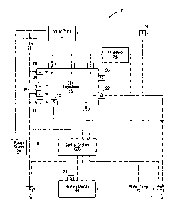
Figure 1 illustrates a block diagram of a bathing unit system 10 in accordance
with a
specific example of implementation. The bathing unit system10 includes a
bathing unit
receptacle 18 for holding water, a plurality of jets 20, a set of drains 22, a
heating module
15 60, two water pumps 11 & 12, a filter 26 and an air blower 24, and a
control system 600.
It should be understood that the bathing unit system 10 could include more or
less bathing
unit components.
The control system 600 receives electrical power from an electric power source
29 and
controls the distribution of power supplied to the various bathing unit
components on the
basis of control signals received from various sensors 70 in order to cause
the desired
operational settings to be implemented. Manners in which the control system
600 can be
used to control the bathing unit components for the regulation of the
operation of the
bathing unit system, such as for example the jets 20, the drains 22, the
heating module 60,
the water pumps 11 & 12, the filter 26 and the air blower 24, are well known
in the art
and are not critical to the invention and as such will not be described in
further detail
here.
The control system 600, in addition to controlling the bathing unit components
used in
the regulation of the operation of the bathing unit system, provides
multimedia
CA 02579949 2007-02-28
89003-71
16
functionality, telephone functionality and/or data network access
functionality to the
users of the bathing unit system 10.
A specific example of implementation of the control system 600 is depicted in
Figure 2a
of the drawings. The embodiment depicted in figure 2a shows a specific
implementation
of the control system 600 providing multimedia functionality. Embodiments of
the
control system 600 implementing telephone functionality and/or data network
access
functionality will be described later on in the specification as variants of
the control
system 600 providing multimedia functionality shown in figure 2a. For the
purpose of
simplicity, the sensors 70 used for monitoring the operation of the bathing
unit
components shown in figure 1 have been omitted from the illustration of Figure
2a.
As shown, the control system 600 includes a control interface 32, a bathing
unit
controller 30 and a multimedia source interface 50 in communication with a
multimedia
output module 52. The bathing unit controller 30 issues signals for
controlling the set
of bathing unit components in bathing unit system 10 (shown in figure 1)
either on the
basis of control signals received from various sensors 70 or on the basis of
user
commands provided through control interface 32. The multimedia source
interface 50
communicates with the bathing unit controller 30 over communication link 64
and
provides access to media content associated with an external media source 53.
The
external media source 53 may be embodied as any number of suitable media
carrier as
will be illustrated later on in the present application. The control interface
32
communicates with the bathing unit controller 30 over communication link 67
and
enables a user to enter information indicative of a desired change in a
certain operational
setting of the bathing unit system. Some non-limiting examples of operational
settings
of the bathing unit system include temperature control settings, jet control
settings and
lighting settings, amongst others. The control interface 32 also provides the
user with
multimedia control functionality. For example, the control interface 32
enables a user
to enter a media control command to obtain information associated to media
content
associated with the external media source 53. The control interface 32 also
enables a
CA 02579949 2007-02-28
89003-71
17
user to cause media content associated with the external media source 53 to be
conveyed
to a user through the multimedia output module 52.
Advantageously, the embodiment depicted in figure 2a enables a user of the
bathing unit
system to control the operational settings of the bathing unit and to access
media content
on the external media source 53 from a same interface, namely control
interface 32.
It will be appreciated that, although the multimedia output module 52 is
depicted as being
connected to the multimedia source interface 50, the multimedia output module
52 may
be connected to the external media source 53, the bathing unit controller 30
or the control
interface 32 in alternative embodiments of the invention. Alternatively still,
the output
module 52 may be an integral part of the control interface 32. For example,
the control
interface 32 may include one or more output modules 52 embodied as audio
speakers
and/or display screens for conveying to the user audio and/or video media
content
associated with the external media source 53. In such an embodiment, media
signals
conveying the audio and/or video media content associated with the external
media
source 53 are transmitted to the control interface 32 by the multimedia source
interface
50 through the bathing unit controller 30. These signals are adapted for
causing audio
and/or video media content to be conveyed to a user of the bathing unit system
through
the display and/or the audio speakers of the control interface 32.
As can be seen from figures 1 and 2a, the components of the control system 600
are
interconnected through a central link namely the bathing unit controller 30.
More
specifically, the bathing unit components of the bathing unit system 10 are in
communication with the control interface 32 through bathing unit controller
30.
Similarly, the communication path between the multimedia source interface 50
and the
control interface 32 goes through the bathing unit controller 30.
Advantageously, this
configuration allows for a single communication link 67 between the bathing
unit
controller 30 and the control interface 32 to carry both control signals
pertaining to the
regulation of the operation of the bathing unit system and signals pertaining
to
CA 02579949 2007-02-28
89003-71
18
multimedia functionality. In embodiments where the communication link 67 is a
wired
connection, this facilitates the installation of the control system 600 since
a single cable
needs to be run from the control interface 32. It will be apparent that the
communication
link 67 could be comprised of multiple physical electrical lines for carrying
various
signals between the control interface 32 and the bathing unit controller 30.
However,
during installation, these multiple physical electrical lines can be run
through a same
physical path. 'Where the communication link 67 is a wireless connection, a
single
wireless transceiver at the control interface 32 can be user to transmit
control signals
pertaining to the regulation of the operation of the bathing unit system and
signals
pertaining to multimedia functionality.
In a variant of control system 600, shown in figure 2b, the control of the
operational
setting of the bathing unit system 10 is provided separately from the
multimedia control
functionality. More specifically, media control functionality is provided to
the user of
the bathing unit by media control interface 55 and the control of the
operational setting
of the bathing unit system 10 is provided through bathing unit control
interface 37. The
media control interface is in communication with bathing unit controller over
communication link 69 and bathing unit control interface 37 is in
communication with
bathing unit controller 30 over communication link 68. Both communication
links may
be either wired or wireless links.
In yet another variant not shown in the figures, media control functionality
is provided
to the user of the bathing unit via both a media control interface such as
media control
interface 55 and a control interface of the type of control interface 32. In
this variant, the
control of the multimedia functionality is provided by two interfaces namely
through a
media control interface 55 dedicated to the control multimedia components and
through
control interface 32 providing control of the operational settings of the
bathing unit
system and control of multimedia functionality.
In a typical interaction, a user enters a media control command at the control
interface
32 (shown in figure 2a) or media control interface 55 (shown in figure 2b). In
a non-
CA 02579949 2007-02-28
89003-71
19
limiting example of implementation, the media control command conveys a
multimedia
function, such as "PLAY", "STOP", "PAUSE", "FAST FORWARD", "REWIND",
"STEP FORWARD", "STEP BACK", "SHUFFLE", "REPEAT", "OPEN FILE" or any
other suitable type of media function with respect to certain media content on
an external
media source 53. Alternatively, the media control command conveys a request to
obtain
a listing of media elements stored on the external media source 53.
The media control command is transmitted from the control interface 32 to the
bathing
unit controller 30 over communication link 67or from media control interface
55 to the
bathing unit controller 30 over communication link 69. The bathing unit
controller 30
receives the media control command and transmits a signal conveying the media
control
command to the multimedia source interface 50 over communication link 64. The
bathing unit controller 30 may perform some processing on the media control
command
or may transmit this media control command to the multimedia source interface
without
processing it. The multimedia source interface 50 processes the signal
conveying the
media control command and causes the functions associated to that media
control
command to be executed. The manner in which the multimedia source interface 50
causes a command to be executed will become apparent to the person skilled in
art in
light of the description presented later on in this specification.
A practical non-limiting implementation of a control system 600 is depicted in
figure 2c
of the drawings. As shown, the control system, designated with reference
numeral 1600,
includes a bathing unit controller 1612, a control interface 1614 and a
multimedia source
interface 1606. The bathing unit controller 1612includes a plurality of
connectors for
interconnecting various bathing unit components. The control interface 1614
and the
multimedia source interface 1606 are connected to respective connectors of the
bathing
unit controller 1612and communicate with bathing unit controller 1612over
communication link 1610 and 1608 respectively. The multimedia source interface
1606
is embodied as a free standing structure including a set of interface
connectors suitable
for establishing connections with various external media sources and output
modules.
A shown, the multimedia source interface 1606 communicates a set of external
media
CA 02579949 2012-11-19
89003-71
sources 1602a-c including a digital audio player 1602b (such as an MP3 player
or
equivalent audio format) and a radio tuner 1602c. The multimedia source
interface 1606
also includes an input for receiving an audio or video signal (labeled as
"AUDIO/VIDEO
IN- in figure 2c) from an external device 1602a. Such an external device may
be, for
5 example, a stereo/video system. The multimedia source interface 1606 also
communicates with an output module 1604 embodied as a speaker in figure 2c. It
will be
apparent to the person skilled in the art in light of the present
specification that several
variations of implementation of control system 600 are possible and that the
example
depicted in figure 2c was presented for the purpose of illustration only.
In the embodiments depicted in figures 2a and 2b, the multimedia source
interface 50 has
been described as a component separate from the bathing unit controller 30 and
the
control interface 32. It will be appreciate that the multimedia source
interface 50 may, in
alternative embodiments, form an integral part of the bathing unit controller
30 or may
form an integral part of the control interface 32. As will be appreciated, in
embodiment
where the multimedia source interface 50 is part of the bathing unit
controller 30, the
communication link 64 will be replaced by internal communication channels
within the
bathing unit controller 30. Similarly, in embodiments where the multimedia
source
interface 50 is an integral part of the control interface 32, the
communication link 64 with
the bathing unit controller 30 will be omitted.
MULTIMEDIA SOURCE INTERFACE 50
Embodiments of the multimedia source interface 50 will now be described. For
the
purpose of simplicity, embodiments where the multimedia source interface 50 is
a
component separate from the bathing unit controller 30 and the control
interface 32 will
be described for the purpose of illustration.
In specific practical examples of implementation, the multimedia source
interface 50 may
be suitable to be located on the top-side of a bathing unit receptacle so that
it can be
CA 02579949 2007-02-28
89003-71
21
accessed by a user positioned in the bathing unit receptacle, on an exterior
panel of the
bathing unit receptacle or in a location remote from the bathing unit
receptacle. Where
the multimedia source interface 50 is to be located in a location remote from
the bathing
unit receptacle, it can be mounted on a wall (for example in or outside a
house) or it may
be integrated in a free standing structure that can be positioned on a
surface. The
multimedia source interface 50 may be in communication with the bathing unit
controller
30 over a wireless or wired communication link.
A functional block diagram of a specific example of implementation of
multimedia
source interface 50 is depicted in figure 3 of the drawings.
As depicted, the multimedia source interface 50 includes a connector interface
260 for
establishing a communication link 200 with an external media source 53, a port
270 for
establishing a communication link 64 with the bathing unit controller 30, an
output
interface 280 for establishing a communication link 66 with an output module
52 and a
processing unit 241.
The port 270 is for receiving signals conveying media control commands from
the
bathing unit controller 30 over communication link 64 and for transmitting
information
through the bathing unit controller 30 to the control interface 32 (depicted
in figure 2a)
and/or to the media control interface 55 (depicted in figure 2b). The
communication link
64 between the multimedia source interface 50 and the bathing unit controller
30 may be
embodied in any suitable format for allowing the multimedia source interface
50 and the
bathing unit controller 30 to exchange signals. The communication link 64 may
be
established over a wired connection or a wireless connection. Where the
communication
link 64 is established over a wireless link, the port 270 includes a wireless
transceiver for
exchanging messages with a corresponding wireless transceiver associated with
the
bathing unit controller 30. The wireless link may be for example a radio
frequency (RF)
link, an infra-red (IR) link or an optical link. Where the communication link
64 is
established over a wireless link, the multimedia source interface 50 may be
positioned
remotely from the bathing unit controller 30 and can be installed for example
inside a
CA 02579949 2012-11-19
89003-71
22
house or in any suitable location removed from the bathing unit system
installation.
The output interface 280 is for releasing a media signal in a format suitable
for causing an
output module 52 to convey at least part of the media content associated with
the external
media source 53 to a user. In a specific example of implementation, the output
interface
280 includes a port for establishing the communication link 66 with the
external output
module 52. As was the case for communication link 64, the communication link
66
between the multimedia source interface 50 and the output module 62 may be
embodied
in any suitable format for allowing the multimedia source interface 50 to
transmit media
signals to output module 62. The communication link 66 may be established over
a
wired connection or a wireless connection. Where the communication link 64 is
established over a wireless link, the output interface 280 includes a wireless
port
including a wireless transmitter for transmitting signals to a corresponding
wireless
receiver associated with the output module 52. In a specific example of
implementation
the output interface 280 includes a wireless port suitable for establishing a
connection
with an output module 52 embodied as a wireless speaker module or a wireless
head-set.
The connection with the wireless speaker module or wireless headset may be
made using
any suitable wireless protocol. In a specific practical implementation, a
short-range
wireless protocol, such as the BLUETOOTH protocol, will be used for effecting
the
connection between the output interface and the wireless speaker module or
wireless
headset. It will however be appreciated that any suitable wireless protocol
may be used.
In addition, although the above description illustrates examples of the output
module 52
as being embodied as a wireless speaker module or wireless headset, it will be
appreciated that the output module 52 may include any suitable wireless or
wired device
suitable for conveying media content to a user including but not limited to a
speaker, a
headset and a display module each of which may be of a wireless or a wired
configuration.
As a variant, not shown in the figures, the output module 52 is an integral
component of
the multimedia source interface 50. In such a variant, the output interface
280 may be
omitted. In yet another variant, the output interface 280 may be connected
directly to the
CA 02579949 2012-11-19
89003-71
23
external media source 53. In such a variant the output interface 280 may also
be omitted
from the multimedia source interface 50.
In yet another variant, not shown in the figures, the output module 52 is
connected to the
control interface 32 or forms an integral component of the control interface
32. In such a
variant the output interface 280 may also be omitted from the multimedia
source interface
50 and media signals conveying media content associated with the external
media source
53 will be transmitted to the control interface 32 through the bathing unit
controller either
through port 270 or through a separate output port.
The connector interface 260 is adapted for establishing a communication link
200 with
the external media source 53 for accessing media content stored on the
external media
source 53. The connector interface 260 may include a connector of any suitable
configuration adapted for coupling to a complementary connector associated
with the
external media source with or without the requirement of an adapter there
between. Such
a connector interface 260 may include, for example, a serial interface
connector, a parallel
interface connector and may be a wired connector or a wireless connector. In a
non-
limiting example of implementation, the connector interface 260 includes a USB
connector interface. Advantageously, a USB connector interface allows
connector
interface 260 to be coupled with an external media source embodied in a UFD
(USB
Flash Drive) which is a common type of storage medium for data files and media
files.
In other specific examples of implementation, the connector interface 260 is
suitable for
exchanging signals with an external media source 53, where the external media
source 53
may be, for example, a CD-drive, a CD changer, a DVD-drive, a radio source
(traditional
AM/FM or satellite), a computer hard drive, an MP3 player, an MP4 player or
any other
type of device storing audio, video and/or electronic written media content
(e.g.
newspaper, journals). The connector interface 260 may also include a connector
interface embodied as a computer network connector, a wireless antenna for
Internet
connection, a television cable connector, a telephone jack and/or a connector
suitable for
engaging a cellular-phone. In will be appreciated that a connector interface
providing
access to the Internet would also enable a user to access internet radio
stations or any
CA 02579949 2012-11-19
89003-71
24
other audio or video source available on the Internet. The Internet connection
could also
give access to an IP phone connection such as for example SKYPE.
Where the external media source 53 is a device implementing media content
processing
functionality for generating media signals in addition to storing media
content, the
connector interface 260 is adapted for engaging the control port of the
external media
source 53 to allow control signals to be transmitted to the external media
source 53 from
the multimedia source interface. In this embodiment, the connector interface
260 may
also be adapted for receiving media signals (for example audio and/or video
signals)
generated by the external media source 53 in response to the control signals.
The
audio/video media signal are communicated to the output interface 280 so that
audio
and/or video signals generated by the external media source 53 can be conveyed
to the
user by output module 52.
The processing unit 241 is in communication with the interface connector 260,
the port
270 and the output interface 280 and provides functional modules for enabling
communication between the control interface 32 shown in figure 2a or the media
control
interface 55 shown in figure 2b (both through the intermediary of bathing unit
controller
30) and the external media source 53. In addition, where the output module 52
is
connected to the multimedia source interface 50, the processing unit 241
provides
functional modules for enabling communication between the output module 52 and
the
external media source 53. The functional modules may, for example, implement
communication protocols, signal format conversions and any other function
required for
enabling communication between the different components 30 53 50 and 52. As
such,
communication paths between the different components 30 53 50 and 52 are
created by
the multimedia source interface 50. Any suitable methods and techniques known
in the
art can be used for providing such communication capability. The specific
manner in
which the functional modules enable the communication between the various
components
is not critical to the invention and as such will not be described in further
detail here.
CA 02579949 2007-02-28
89003-71
The processing unit 241 is responsive to media control commands originating
from the
control interface 32 (shown in figure 2a) and received from the bathing unit
controller
at the port 270 for causing the functions associated to the media control
commands
to be executed. The processing unit 241 is responsive to media control
commands to
5 cause a media signal to be generated, the media signal conveying at least
part of the
media content stored on the external media source 53. The processing unit 241
then
causes the generated media signal to be released at the output interface 280.
The media
signal released at the output interface 280 in a format suitable for causing
the output
module 52 to convey at least part of the media content associated with the
external media
10 source 53 to a user. The processing unit 241 is also responsive to media
control
commands to access information associated to media content stored on the
external
media source 53 and to cause a signal conveying the information associated to
media
content stored on the external media source to be transmitted to the bathing
unit
controller 30 through port 270.
The functions associated to the media control commands may be executed in
totality or
in part by the processing unit 241, in which case the processing unit 241 will
include
media content processing functionality, or alternatively may be executed by
the external
media source 53 on the basis of signals transmitted from the multimedia source
interface
50 to the external media source 53. In the latter case, the media content
processing
functionality will be implemented by the external media source 53.
In a first specific example of implementation, the multimedia source interface
50
transmits a control signal to the external media source 53 for causing the
latter to execute
the functions associated with media control command. In this first specific
example of
implementation, the multimedia source interface 50 will typically include
suitable format
conversion modules for converting the media control command originating from
the
control interface 32 (or media control interface 55) into a format that is
compatible with
the external media source 53. The multimedia source interface 50 then
transmits the
converted media control command to the external media source 53 for execution.
Such
media control commands may include commands for implementing functions such as
CA 02579949 2007-02-28
89003-71
26
"PLAY", "STOP", "PAUSE", "FAST FORWARD", "REWIND", "STEP FORWARD",
"STEP BACK", "SHUFFLE", "REPEAT", "OPEN FILE" or any other desirable type
of media function with respect to media content. Such media control commands
are
then executed by the external media source 53 which processes the media
content stored
on the external media source 53 on the basis of the media control commands to
generate
a media signal conveying at least part of the media content associated with
the external
media source. The external media source 53 then transmits the media signal
over
communication link 200 to the multimedia source interface 50. The multimedia
source
interface 50 receives the media signal conveying at least part of the media
content
associated with the external media source and releases at output interface 280
the media
signal in a format suitable for causing the output module 52 to convey at
least part of the
media content associated with the external media source to a user. The
multimedia
source interface 50 is also adapted for enabling information typically
displayed on a
control panel associated to an external media source 53 and conveying
information as to
the media content of the external media source 53 to be transmitted to the
control
interface 32 for display to the user. In a typical interaction, the multimedia
source
interface 50 receives signals from the external media source 53 conveying
information
to be displayed on the control interface 32. The multimedia source interface
50 is
adapted for releasing at output interface 270 a signal for causing a display
associated
with the control interface 32 to convey at least part of the media content
associated with
the external media source to a user or other suitable type of information
typically
displayed on a control panel associated to an external media source 53. In a
non-limiting
example, such a configuration would allow, an external media source 53
embodied as an
MP3 player or other similar type of audio device (e.g. iPODTM) or MPEG player
to be
connected to the multimedia source interface 50 through interface connector
260 and to
provide display information of the type typically displayed on such a device
at the
control interface 32 (shown in figure 2a). Such information may include,
without being
limited to, artist names and/or band names, audio album titles, song titles,
movie titles,
written media identifiers, file size and timing information. In a specific
example of
implementation, the media control command originating from the control
interface 32 (or
media control interface 55) may also convey a request to obtain a listing of
media
CA 02579949 2007-02-28
89003-71
27
elements stored on the external media source 53. In such cases the multimedia
source
interface 50 is adapted for receiving a signal conveying the listing of media
elements
from the external media source 53. The multimedia source interface 50 then
generates
a signal conveying the listing of media elements and transmits this signal
through the
bathing unit controller 30 to the control interface 32 shown in figure 2a (or
media control
interface 55 shown in figure 2b) for display.
In a second specific example of implementation, the processing unit 241
includes
functional modules for locally providing media content processing
functionality for
executing the functions associated with media control commands originating
from the
control interface 32 (or media control interface 55). The multimedia source
interface 50
may, for example, includes functional modules for accessing media content on
the
external media source 53 and for implementing functions such as "PLAY",
"STOP",
"PAUSE", "FAST FORWARD", "REWIND", "STEP FORWARD", "STEP BACK",
"SHUFFLE", "REPEAT", "OPEN FILE" or any other desirable type of media function
with respect to the media content. In this second specific example of
implementation,
the processing unit 241 includes a media-processing unit 240, as depicted in
figure 3, for
implementing these functional modules. The media-processing unit 240 processes
the
media content obtained from the external media source 53 to generate a media
signal
conveying at least part of that media content to a user. The processing unit
241 then
releases that media signal at output interface 280 in a format suitable for
output module
52. In a non-limiting examples of implementation, the media-processing unit
240 may
include functional modules for implementing MP3 (or other audio format) player
functionality, MPEG player functionality, MP4 (or other video format) player
functionality, CD player functionality and DVD player functionality amongst
others.
In a specific example of implementation, the media content associated with the
external
media source 53 includes electronic written media in a certain format (such as
a ".pdf'
file in a non-limiting implementation). In such cases, the media-processing
unit 240 may
include functionality for generating a display media signal on the basis of an
electronic
written media (such as a ".pdf' data file for example). In this second
specific example
of implementation, the multimedia source interface 50 also includes functional
modules
CA 02579949 2012-11-19
89003-71
28
for accessing a listing of media elements stored on the external media source
53 and for
transmitting a signal conveying this listing for display at the control
interface 32 (or
media control interface 55). In this embodiment, the external media source 53
may
conveniently be embodiment as a media carrier medium, such as a USB Flash
drive,
without imbedded media content processing functionality since such
functionality is
integrated in the multimedia source interface 50.
Optionally, in variants of implementations, the multimedia source interface 50
includes a
built-in radio device (AM/FM and/or Satellite), MP3/MP4/MPEG or equivalent
player
with local memory storage capabilities, wireless antenna for Internet
connection,
telephone jack or cordless phone antenna, cell-phone antenna and television
cable
receiver amongst others.
A functional block diagram of a variant of the multimedia source interface 50,
designated
as multimedia source interface 50', is depicted in figure 4 of the drawings.
In this
variant, the multimedia source interface 50' includes set of connector
interfaces 260a-e
each being analogous to the connector interface 260 described with reference
to figure 3.
The connector interfaces 260a-e are adapted for establishing respective
communication
links 200a-e with external media sources 53a-e. The multimedia source
interface 50' also
includes a port 270 for establishing a communication link 64 with the bathing
unit
controller 30 and a processing unit 241'. In the variant depicted in figure 4,
the
multimedia source interface 50' also includes a plurality of output interfaces
280a-c
(analogous to output interface 280 described with reference to figure 3) for
establishing
communication links 66a-c with respective output modules 52a-c. It will be
appreciated
that other embodiments of the multimedia source interface 50' may include
multiple
connector interfaces and a single output interface or multiple output
interfaces and a
single connector interface.
In accordance with a specific example, the set of external media sources 53a-e
may
include at least two external media sources, each external media source
storing respective
media content. The external media sources 53a-e in the set may be of a same
type or of
CA 02579949 2012-11-19
89003-71
29
different types. In a specific example, the connector interfaces 260a-e are
configured for
engaging at least two different types of external media sources. In such an
implementation, the multimedia source interface 50' comprises a first
interface connector
suitable for coupling with a complementary connector of a first type
associated with a
first type of external media source and a second interface connector suitable
for coupling
with a complementary connector of a second type associated with a second type
of
external media source. In a non-limiting example of implementation, the first
interface
connector is a USB connector interface and the second interface connector is
suitable for
coupling with a complementary connector associated to an MP3 (or other audio
format)
player. It will be appreciated that the set of connector interfaces 260a-e may
include
multiple connector interfaces adapted for engaging a same type of external
media source.
In a specific implementation, the set of output interfaces 280a-c includes at
least two
output interfaces where each output interface is adapted to engage a
respective output
module. The output interfaces 280a-c in the set may be of a same type or of
different
types. In a specific example, the output interfaces 280a-c are configured for
engaging at
least two different types of output modules for example a first output module
embodied
as a display screen and a second output module embodied as a speaker. In such
an
implementation, the multimedia source interface 50' comprises a first output
interface
suitable for communicating with a complementary interface of a first type
associated with
a first type of output module and a second output interface suitable for
communicating
with a complementary interface of a second type associated with a second type
of output
module. It will be appreciated that the set of output interfaces 280a-c may
include
multiple output interfaces adapted for engaging a same type of output module.
The processing unit 241' is analogous to processing unit 241 described with
reference to
figure 3 and implements similar functionality. The processing unit 241'
provides
functional modules for enabling communication, through the bathing unit
controller 30,
between the control interface 32 shown in figure 2a and the set external media
source
53a-d. In addition, where multiple output modules 52a-c are connected to the
multimedia
CA 02579949 2012-11-19
89003-71
source interface 50, the processing unit 241' provides functional modules for
enabling
communication between the output modules 52a-c and the external media sources
53a-e.
The functional modules may, for example, implement communication protocols,
signal
format conversions and any other function required for enabling communication
between
5 the different components. Any suitable methods and techniques known in
the art can be
used for providing such communication capability. The specific manner in which
the
functional modules enable the communication between the various components is
not
critical to the invention and as such will not be described in further detail
here. The
processing unit 241" is also operative for generating and transmitting
information to the
10 control interface 32 (shown in figure 2a) via the bathing unit
controller 30 for conveying
to a user a listing of the set of external media sources 53a-e which are in
communication
with the multimedia source interface 50".
Practical implementations of multimedia source interfaces and of control
systems making
15 use of a multimedia source interface will now be described for the
purpose of illustration.
Practical implementation #1
A first specific practical implementation of multimedia source interface will
now be
20 described with reference to figure 5 of the drawings. It will be
appreciated that this
practical implementation is depicted for the purpose of illustration and that
various other
implementations of multimedia source interfaces are possible.
The multimedia source interface, designated with reference numeral 451,
includes a front
25 panel 450 with two interface connectors 402 and 400, a back portion 453
positioned in
the back of the front panel 450 and holding a processing unit (not shown), a
first
communication link 410 for communicating with the bathing unit controller 30
and a
second communication link 412 for transmitting media signals to an output
module 52.
CA 02579949 2007-02-28
89003-71
31
The multimedia source interface 451 is also connected to a power source (not
shown),
which may be a local power source (such as a battery) or may be connected to
an external
power supply. The external power supply may be provided through the bathing
unit
controller 30 or through other suitable electrical wiring to the multimedia
source
interface 451.
The multimedia source interface 451 is configured to be mounted to a surface,
such as
an outside panel of a bathing unit or to a wall. The configuration shown is
preferably
mounted to a surface having a recess adapted for receiving the back portion
453 of the
multimedia source interface 452 such that the front panel 450 covers that
recess.
In the embodiment depicted, the first interface connector 400 is a serial USB
type
connector interface adapted for engaging a complementary connector associated
with
external media source embodied as a UFD (USB Flash Drive) 460. The UFD (USB
Flash Drive) 460 stores media content such as for example, audio files, video
files,
electronic written media (e.g. newspaper, journals, bathing unit owner's
manual) or any
other suitable media content that a user of the bathing unit may want to
access. The
media content stored on the UFD (USB Flash Drive) 460 may be encoded using any
suitable encoding protocol.
The second interface connector 402 is an audio input connector adapted for
engaging an
audio output line of an audio device 467.
The communication link 410 for communicating with the bathing unit controller
30 is
embodied as a wired communication cable for carrying bi-directional
communication
signals between the bathing unit controller 30 and the multimedia source
interface 451.
The communication link 412 for transmitting media signals to an output module
52 is
embodied as a wired communication cable for carrying media signals to an
output
module. Depending on the type of output module and type of media signals to be
carried,
the communication link 412 will be embodied in a suitable physical medium for
allowing
CA 02579949 2012-11-19
89003-71
32
the desired media signals to be communicated with the output module. For
example,
where the media signals is a video signal, the communication link 412 will be
embodied
in a physical medium providing sufficient bandwidth for carrying a video
signal.
The processing unit (not shown in the figure) is located in the back portion
453 of the
multimedia source interface 451 and is in communication with the two interface
connectors 402 and 400, the first communication link 410 and the second
communication
link 412. The processing unit is adapted for implementing the functionality
described
with reference to processing units 241 and 241' shown in figures 3 and 4. In
this specific
example, the processing unit implements media content processing functionality
for
allowing functions associated to the media control commands originating from
the
control interface 32 to be executed in totality or in part by the processing
unit. For
example, the processing unit may include functional modules for implementing
functions
such as "PLAY", "STOP-, "PAUSE", "FAST FORWARD", "REWIND-, "STEP
FORWARD", "STEP BACK", "SHUFFLE", "REPEAT" or any other desirable type of
media function with respect to the media content. For example, where the
processing
unit may implement MP3 (or other audio format) player functionality, MP4 (or
other
video format) player functionality.
A non-limiting example of implementation of a processing unit suitable for in
the
multimedia source interface 451 is depicted in figure 6 of the drawings.
As depicted, the processing unit, designated with reference numeral 419,
includes
functionality for implementing a USB controller 604, a file allocation table
(FAT) system
module 612, a serial interface controller 610 and a media processing unit 606
including
amongst others an MP3 decoder module 608. In the specific example shown, the
serial
interface controller 610 allows the multimedia source interface 451 to
communicate with
the bathing unit controller 30 through serial connector 411. Figure 6 also
depicts in
greater detail a specific implementation of an output interface 280 including
a
BLUETOOTH module 614 and an output audio jack 616. Figure 6 also depicts a
specific implementation of a power supply control module 417 including a
battery 600
and a voltage regulator 602. Manners in which the various modules of the
processing
CA 02579949 2012-11-19
89003-71
33
unit 419 can be implemented is well known to the person skilled in the art
will vary from
one implementation to the other. As such, these modules will not be described
further
here.
Practical implementation #2
A second specific practical implementation of the multimedia source interface
will now
be described with reference to figures 7a, 7b and 8 of the drawings.
The multimedia source interface, designated with reference numeral 800,
includes a body
defining a cavity 804 suitable for receiving therein an external media source
808 storing
media content. The multimedia source interface 800 also includes an interface
connector
806 positioned within the cavity 804 defined by the body. The interface
connector 806 is
of a suitable type for engaging a complementary connector (not shown)
associated with
the external media source 808 for accessing media content stored on the
external media
source 808. In the non-limiting example depicted, the external media source
808 is an
MP3 player (or other equivalent audio format player). hi a specific non-
limiting
example, the cavity 804 defined by the body of the multimedia source interface
800 is
such that it can receive therein the external media source 808 so that the
external media
source 808 substantially lies within the cavity 804. Since different external
media
sources 808 may have different shapes and sizes, embodiments of the multimedia
source
interface 800 will have the cavities with different configurations. Although
the example
of implementation shown in figure 7a shows a single interface connector 806
positioned
within the cavity 804, it will be appreciated that alternative implementations
of the
multimedia source interface 800 may includes multiple interface connectors
positioned
within the cavity 804 defined by the body of the multimedia source interface
800. As
such, the apparatus may comprise a set of interface connectors positioned
within the
cavity defined by the body of the apparatus, the set of connectors including
at least two
connectors. The interface connectors in the set of interface connectors are
suitable for
engaging respective complementary connectors associated with external media
sources of
different types. In a specific implementation, the set of connectors includes
at least two
connectors that are suitable for coupling with different types of
complementary
CA 02579949 2012-11-19
89003-71
34
connectors associated with external media sources.
Optionally, as shown in the specific example depicted in figure 7a, the
multimedia source
interface 800 includes one or multiple positioning members 812 for positioning
the
external media source 808 within the cavity 804. The positioning members 812
are
adapted for releasably engaging the external media source 808 so that it can
be securely
positioned within the cavity 804. The positioning members 812 may have
different
configurations adapted for securing external media sources having different
shapes. In
the non-limiting example depicted, the multimedia source interface 800
includes two
positioning members 812 adapted for resiliently securing the external media
source 808
there between.
The multimedia source interface 800 also includes a communication entity 822
(shown in
figure 7b) operative for exchanging signals with the bathing unit controller
30 and a
processing unit 824 in communication with the interface connector 806 (over
communication link 810) and the communication entity 822. The processing unit
824 is
adapted for implementing similar functionality as that described with
reference to
processing units 241 or 241 (shown in figures 3 and 4). In the specific non-
limiting
example depicted, the processing unit 824 is responsive to media control
commands
received from the bathing unit controller 30 at communication entity 822 for
causing a
media signal to be generated by the external media source 808, the media
signal
conveying at least part of the media content stored on the external media
source 808.
More specifically, the processing unit 824 is responsive to media control
commands
received from the bathing unit controller 30 for transmitting signals
conveying the media
control commands to the external media source 808 over interface connector
806. The
functions associated to the media control commands are executed by the
external media
source 808 on the basis of signals transmitted from the multimedia source
interface. The
external media source 808 then releases the media signal for transmission to
multimedia
source interface 800 either through interface connector 806 or through another
interface
connector (not shown) on the multimedia source interface 800. The apparatus
also
includes an output interface 837 in communication with the processing unit
824. The
CA 02579949 2007-02-28
89003-71
output interface 837 is for releasing the media signal generated by the
external media
source 808 in a format suitable for causing an output module (not shown) to
convey at
least part of the media content associated with the external media source to a
user.
5 In a specific example of implementation, the body of the multimedia
source interface 800
is designed to be mounted to a surface, such as an outside panel of a bathing
unit or to
a wall. The configuration shown is preferably for mounting to a surface having
a recess
adapted for receiving the back portion of the multimedia source interface 800
such that
the front panel 802 covers the recess. In a non-limiting implementation, for
the
10 installation of the multimedia source interface 800, a recess is created
in the outside panel
of the bathing unit for receiving therein the body of the apparatus. Figure 8
of the
drawings depicts a bathing unit system 700 with the multimedia source
interface 800
positioned on an outside panel 706 of the bathing unit receptacle. Figure 8
also shows
a control interface 704 positioned on the topside of the bathing unit
receptacle. The
15 control interface 704 is analogous to control interface 32 (depicted in
figure 2a) and is
in communication with the multimedia source interface 800 through a bathing
unit
controller (not shown in the figure).
Referring back to the specific example of implementation depicted in figure
7a, the
20 multimedia source interface 800 includes a cover member 814 for engaging
the body
multimedia source interface 800 such as to substantially enclose the cavity
804 defined
by the body. The cover member 814 may be a component that can be separated
from the
body during normal use or may be moveably connected to the body. In the
specific
implementation shown, the cover member 814 is hingedly connected to the body
and is
25 movable between a first position in which it substantially encloses the
cavity 804 defmed
by the body and a second position in which it allows access to a user to the
cavity 804
defined by the body. In a specific implementation, the cover member 814 is
suitable for
engaging the body such as to substantially prevent water from entering the
cavity 804
during use of the bathing unit system.
In a specific example of implementation, the body of the multimedia source
interface
CA 02579949 2012-11-19
89003-71
36
includes a communication disconnect member (not shown in the figures) adapted
for
causing the interface connector 806 to acquire a state in which the device 808
can be
safely disconnected from the interface connector 806. More specifically, while
the device
808 is being accessed by the multimedia source interface 800 through interface
connector
806, disconnecting the device 808 may cause damage to either the external
media source
808 or the connector 806. Such damage may cause media content on the device
808 to be
lost or corrupted for example. In addition, when the multimedia source
interface 800 is
positioned near water, the users of the system may be wet when accessing the
multimedia
source interface 800. In such cases, the communication disconnect member
provides a
mechanism that may be used for removing power from the multimedia source
interface
800 during user access to prevent an unsafe situation.
In a specific example of implementation, the communication disconnect member
includes
a circuit element in communication with the cover member 814. When the cover
member
814 is engaged with the body such as to substantially enclose the cavity 804
defined by
the body, the circuit element enables power to be communicated to the
connector 806 and
enables the multimedia source interface 800 to access media content on the
external
media source 808. When the cover member is positioned such as to allow access
to a user
to the cavity 804 defined by the body, the circuit element in the
communication
disconnect member prevents power to be communicated with the connector 806 so
that
the external media source 808 can be disconnected from the multimedia source
interface
800.
Alternatively, the communication disconnect member is in the form of a user
controllable
device (not shown in the figure). The user controllable device can be actuated
by a user
to cause the connector 806 to acquire a first state in which access to the
external media
source 808 is permitted and the external media source 808 can be safely
physically
disconnected from the connector 806. The user controllable device can also be
actuated
by a user to cause the connector 806 to acquire a second state in which the
external media
source 808 should not be physically disconnected from the connector 806 since
disconnection may cause damage to either the external media source 808 or the
connector
CA 02579949 2012-11-19
89003-71
37
806. In practical implementations, the user controllable device may be in the
form of a
button or a switch.
In yet another alternative embodiment, the communication disconnect member
include a
circuit element in communication with the one or multiple positioning members
812. The
circuit element of the communication disconnect member is adapted for
detecting when
the external media source 808 is dislodged from the positioning members 812 to
cause
the connector 806 to acquire a state in which the external media source 808
can be safely
physically disconnected from the connector 806. Such a circuit element may
include for
example an optical sensor for detecting the presence of the external media
source 808 at
the positioning members 812.
It will be appreciated that other embodiments for the communication disconnect
member
may be used for causing the interface connector 806 to acquire a state in
which the device
808 can be safely disconnected from the interface connector 806.
In a specific example of implementation, a visual indicator 842 is provided
for indicating
to the user whether or not the external media source 808 can be safely
physically
disconnected from the connector 806. The visual indicator 842 may, for
example, be
positioned in proximity to the multimedia source interface 800, on the
exterior surface of
the body of the multimedia source interface 800, on the cover member 814 or
within the
cavity 804 defined by the body of the multimedia source interface 800. In a
non-limiting
example, the visual indicator 842 is in the form of a light element, for
example an LED.
The LED conveys to a user that the external media source 808 should not be
physically
disconnected from the connector 806 when the LED is "ON" and that the external
media
source 808 may be safely physically disconnected from the connector 806 when
the LED
is "OFF-. Other manners for conveying whether or not the external media source
808
can be safely physically disconnected from the connector 806 may be envisaged
by the
person skilled in the art in light of the present description.
CA 02579949 2012-11-19
89003-71
38
Practical implementation #3
A third specific practical implementation of the multimedia source interface
will now be
described with reference to figure 9 of the drawings.
The multimedia source interface, designated with reference numeral 310, is
part of a
control system for a bathing unit system 300, the control system being
suitable for
controlling a set of bathing unit components and for providing multimedia
functionality
to the user. As illustrated, the bathing unit system 300 includes a bathing
unit receptacle
319, a control system and a set of bathing unit components. For the purpose of
simplicity,
the set of bathing unit components, which may include components similar to
those
depicted in figure 1 of the drawings, have been omitted from the illustration
depicted in
figure 9. The control system includes a multimedia source interface 310 in
communication with a bathing unit controller 312 over communication link 329.
The
bathing unit controller 312 is analogous to bathing unit controller 30 (shown
in figure 2a)
an implements similar functionality. The multimedia source interface 310 is
analogous to
the multimedia source interfaces 50 or 50" described above with reference to
figures 2, 3
and 4 of the drawings and implements similar functionality. In this example,
communication link 329 is a wireless link.
As shown, the multimedia source interface 310 includes one or more connector
interfaces
for enabling access to media content associated with one or more external
media sources
including external media source 348. The multimedia source interface 310
includes an
output interface for releasing a signal suitable for causing an output module
to convey at
least part of the media content associated with the external media source 348
to a user. In
the specific embodiment depicted, the output interface is adapted for
communicating with
an output module embodied as a wireless headset 306 or other wireless speaker
device
over wireless communication link 308. Any suitable communication protocol for
providing communication between the multimedia source interface 310 and the
wireless
headset 306 may be used. In a non-limiting example of implementation, a
communication protocol for close proximity audio communication, such as the
CA 02579949 2012-11-19
89003-71
39
BLUETOOTH protocol, is used.
The control system also includes a media control interface 302 in
communication with
the bathing unit controller 312 over communication link 369. In this specific
example,
communication link 369 is a wired connection. The media control interface 302
is shown
as being positioned in the topside of the bathing unit receptacle 319 and is
accessible by a
user located in the bathing unit receptacle 319 however it may also be
positioned in other
suitable locations on the bathing unit receptacle. The media control interface
302 is
analogous to media control interface 55 (shown in figure 2b) and implements
similar
functionality.
The media control interface 302 enables a user to access the external media
source 348
and to control the functions of the external media source 348. More
specifically, using
the controls on the media control interface 302, the user can enter a media
control
command to obtain information associated to media content associated with the
external
media source 348. The media control command is transmitted over communication
link
369 to the bathing unit controller 312 and then over communication link 329 to
the
multimedia source interface 310. The multimedia source interface 310 then
sends a
signal to the external media source 348 conveying the media control command. A
signal
conveying the requested information is then generated and transmitted from the
multimedia source interface 310 through bathing unit controller 312 for
display at the
media control interface 302. Such information may include for example a
listing of the
media content on the external media source 348.
The user may also use the controls on the media control interface 302 to enter
a media
control command for causing a signal to be released at the output interface of
the
multimedia source interface 310 for causing the wireless headset 306 to
release an audio
signal derived from media content associated with the external media source.
The media
control command is transmitted over communication link 369 to the bathing unit
controller 312 and then over communication link 329 to the multimedia source
interface
310. The multimedia source interface 310 then sends a signal to the external
media
CA 02579949 2012-11-19
89003-71
source 348 conveying the media control command. A media signal is generated
conveying media content associated to the external media source 348. The media
signal
is then released at the output interface of the multimedia source interface
310 for
transmittal over wireless link 308 to the wireless headset 306 for causing the
headset 306
5 to convey an audio signal derived from media content associated to the
external media
source 348.
Practical implementation #4
10 A fourth specific practical implementation of multimedia source
interface will now be
described with reference to figures 10 of the drawings.
The multimedia source interface, designated with reference numeral 1004, is
part of a
control system 1000 for a bathing unit system, the control system 1000 being
suitable for
15 controlling a set of bathing unit components in a bathing unit system
and for providing
telephony related functionality. The control system 1000 comprises a bathing
unit
controller 30 suitable for issuing signals for controlling a set of bathing
unit components
in a bathing unit system. The control system 1000 also comprises a multimedia
source
interface 1004 in communication with the bathing unit controller 30, the
multimedia
20 source interface 1004 enabling access to a telephone network 1014. The
multimedia
source interface 1004 is analogous to the multimedia source interface 50
described above
with reference to figures 2a, 2b and 3 and may implement similar communication
interconnection functionality. The control system 1000 also includes a
telephone control
interface 1018 in communication with the bathing unit controller 30. The
telephone
25 control interface 1018 is operative for enabling a user within the
bathing unit system to
access the telephone network 1014 by sending a telephone control command to
the
multimedia source interface 1004 through the bathing unit controller 30. In a
specific
non-limiting example of implementation, the telephone control interface 1018
includes an
auxiliary telephone keyboard including a dial pad and actuators for picking up
a call and
30 terminating a call. Alternatively, the telephone control interface 1018
includes other user
operable inputs for performing telephone-related actions or other
functionality, such as,
for example, speech recognition capability for enabling voice dialing. The
telephone
CA 02579949 2012-11-19
89003-71
41
control interface 1018 may be a standalone control interface or may be an
integral part of
a bathing unit control interface, where the bathing control interface is
operative for
enabling a user to enter information indicative of a desired change in a
certain operational
setting of the bathing unit system.
The multimedia source interface 1004 includes one or more connector
interfaces,
including connector interface 1008, for establishing a communication link with
the
telephone network 1014. The connector interface 1008 may be a standard
telephone jack
providing for a wired connection to the telephone network 1014 or may be of
form
suitable for engaging a mobile (cellular type) phone. Telephone-related
functionality,
including call-pick-up, call termination and initiating a telephone call, may
be
implemented either by the multimedia source interface 1004, by the telephone
control
interface 1018 or by a peripheral unit (not shown in the figure) to be
connected between
the telephone network 1014 and connector interface 1008.
The multimedia source interface 1004 includes an output interface for
releasing a signal
suitable for causing a voice module 1002 to convey audio signals to a user. In
the
specific embodiment depicted the output interface is adapted for communicating
with an
output module embodied as a wireless headset over wireless communication link
1010.
Any suitable communication protocol for providing communication between the
multimedia source interface 1004 and the headset may be used. In a non-
limiting
example of implementation, a communication protocol for close proximity audio
communication, such as the BLUETOOTH protocol, is used for providing
communication between the voice module 1002 and the multimedia source
interface
1004. It will be appreciated that although the communication link 1010 between
the
voice module 1002 and the multimedia source interface 1004 has been depicted
as a
wireless link, embodiments where communication link 1010 is a wired link are
possible.
The voice module 1002 includes an audio output for conveying voice signals
transmitted
by the multimedia source interface 1004 and originating from the telephone
network
1014. Optionally, the voice module
CA 02579949 2007-02-28
89003-71
42
1002 also includes a microphone and is adapted for transmitting signals
derived from a
spoken utterance of a user at the voice module 1002 to the multimedia source
interface
1004 for transmission to the telephone network 1014. Alternatively, a
microphone is
provided at telephone control interface 1018 instead or in addition to the
microphone at
the voice module 1002. Where the telephone control interface 1018 includes a
microphone for receiving voice signals from the user of the bathing unit
system, the
voice signals are transmitted to the telephone network 1014 by traveling
through the
bathing unit controller 30 and the multimedia source interface 1004.
Practical Implementation #5
A fifth specific practical implementation of multimedia source interface will
now be
described with reference to figures 11 of the drawings.
The multimedia source interface, designated with reference numeral 1304, is
part of a
control system 1300 for a bathing unit system, the control system 1300 being
suitable for
controlling a set of bathing unit components in a bathing unit system and for
providing
data network access functionality. The control system 1300 comprises a bathing
unit
controller 30 suitable for issuing signals for controlling a set of bathing
unit components
in a bathing unit system.
The control system 1300 also comprises a multimedia source interface 1304 in
communication with the bathing unit controller 30, the multimedia source
interface 1304
enabling access to a public or private network 1314 (e.g. INTRANET or
INTERNET).
The multimedia source interface 1304 is analogous to the multimedia source
interfaces
50 described above with reference to figures 2a, 2b and 3 and may implement
similar
communication interconnection functionality. The multimedia source interface
1304
includes a port 1308 suitable for communicating with a network interface
device 1312.
The multimedia source interface 1304 also includes a port for communicating
with a
display module 1302. In the embodiment depicted the multimedia source
interface 1304
communicates with the display module 1302 over a wireless communication link
1310
CA 02579949 2012-11-19
89003-71
43
however it may communicate with over a wired communication in alternative
specific
examples of implementation.
The control system 1300 also includes a browser control interface 1318 in
communication with the bathing unit controller 30. The browser control
interface 1318 is
operative for enabling a user to access the public or private data network
1314
(INTRANET or INTERNET) by sending a data network control command to the
multimedia source interface 1304 through the bathing unit controller 30. The
browser
control interface 1318 includes an input module allowing a user to provide
commands for
accessing various information on network 1314. Such an input device may
include a
keyboard, pointing device, touch sensitive screen or any other suitable type
of user
operable input device. The browser control interface 1318 may be a standalone
control
interface or may be an integral part of a bathing unit control interface,
where the bathing
control interface is operative for enabling a user to enter information
indicative of a
desired change in a certain operational setting of the bathing unit system.
The multimedia source interface 1304 includes one or more connector
interfaces,
including connector interface 1308, for establishing a communication link with
the public
or private data network 1314 (INTRANET or INTERNET). The connector interface
1308 may be a standard Ethernet jack providing for a wired connection to the
network
interface device 1312 or may be in a form suitable for engaging a wireless
network
interface device. The network interface device 1312 may be any device suitable
for
providing network connectivity. Such devices are beyond the scope of the
present
application and as such will not be described further here. Moreover, although
the
network interface device 1312 has been shown to be a component separate from
the
multimedia source interface 1304, the of the network interface device 1312 may
be
imbedded in the multimedia source interface 1304 in certain specific examples
of
implementation of the invention.
The multimedia source interface 1304 also includes an output interface for
releasing a
signal suitable for causing display module 1302 to display information to a
user in visual
CA 02579949 2012-11-19
89003-71
44
format. It will be appreciated that although the display module 1302 has been
shown as
being connected to the multimedia source interface 1304, in alternative
embodiments the
display module 1302 will be connected to the browser control interface 1318 or
will be an
integral part of the browser control interface 1318. In such an alternative
implementation, the browser control interface 1318 will preferably includes
required
browser type software components for displaying to a user information obtained
for the
public or private data network 1314 (INTRANET or INTERNET). Alternatively,
such
software may be included as part of the multimedia source interface 1314 or as
part of the
network interface 1312.
CONTROL INTERFACE
Exemplary embodiments of the control interface 32 depicted in figure 2a will
now be
described. For the purpose of the present description, the examples described
will be
directed to a control interface 32 enabling a user of the bathing unit system
to control the
operational settings of the bathing unit and to control multimedia
functionality,
telephone-related functionality and data network access functionality. It will
be apparent
to the person skilled in the art in light of the present description that
embodiments of the
invention providing multiple interfaces for controlling sub-combinations of
these
functions are possible.
As depicted in figure 2a, the control interface 32 communicates with the
multimedia
source interface 50 by sending signals through the bathing unit controller 30.
Similarly,
the control interface 32 receives incoming signals from the bathing unit
controller 30.
Such incoming signals include signals conveying operational settings of the
bathing unit
and signals originating from the multimedia source interface 50 including
signals related
to multimedia functionality, telephone functionality and/or data network
access
functionality.
With reference to figures 12a-12c, there is shown a control interface 32
suitable for use in
the control system shown in figure 2a. The control interface 32, in accordance
to the
CA 02579949 2007-02-28
89003-71
practical implementation depicted, includes a display screen 519, a set of
user operable
controls for allowing a user to enter commands and a processing unit (not
shown)
implementing the functionality of the control interface 32. The control
interface 32 will
typically be installed such as to be accessible by a user making use of the
bathing unit
5 system and is in communication with the bathing unit controller 30 over
communication
link 67.
In the example depicted, the user operable controls on the control interface
32 are in the
form of keys or buttons. Each button or key is associated with a respective
function that
10 is activated when the key is pressed. It will be appreciated that other
suitable types of
user operable controls may be provided for allowing a user to enter commands
such as,
for example, a microphone connection to a speech recognition unit and a touch
sensitive
screen amongst others.
15 The display screen 519 provides information to the user about the bathing
unit
components in the bathing unit system 10 (depicted in figure 1) and provides a
menu
driven interface. In the specific embodiment depicted, the function associated
to a given
button or key on the control interface 32 will be modified depending on the
information
displayed on the display screen 519.
More specifically, the control interface 32 can be configured to provide
control to a
number of components in the bathing unit system including, without being
limited to,
multimedia functionality, telephony functionality, intemet browsing
functionality and the
regulation of the operation of the bathing unit system, amongst others. In
order to allow
the user to control these various components, the control interface 32
provides a menu
driven interface displayed in the display screen 519 allowing the user to
select the
components or functionality that he wishes to control. In the example shown in
figure
12a, the display screen 519 displays a menu list with the following elements:
> SPA
> AUDIO
> INTERNET
CA 02579949 2007-02-28
89003-71
46
> TELEPHONE
But actuating a button in the set of buttons 500, the element in the menu list
aligned with
the actuated button is selected. In order for the user to access the audio
system, for
example, the user actuates button 500b. Similarly, in order for the user to
access the
Internet system, the user actuates button 500c and so on.
When the "AUDIO" sub-menu is selected by the user by actuating button 500b
aligned
with the menu element "AUDIO", media control signals are caused to be
transmitted
from the control interface 32 to the bathing unit controller 30 over
communication link
67 and then are communicated to the multimedia source interface 50 (all shown
in figure
2a). In response, the multimedia source interface 50 causes a signal to be
transmitted to
the control interface 32 through the bathing unit controller 30, the signal
conveying
information associated with external media sources connected to the multimedia
source
interface 50. Where multiple external media sources are connected to the
multimedia
source interface 50, information conveying the set of external media sources
is
transmitted to the control interface 32.
Figure 12b depicts an exemplary embodiment of the control interface 32 and the
display
screen 519 when the user actuates button 500b aligned with the menu element
"AUDIO"
in figure 12a.
As shown, in response to the actuation of actuates button 500b in figure 12a,
a new
listing of elements is displayed in display screen 519. In this specific
implementation,
the listing includes media source information conveying a set of external
media sources
that can be controlled from the control interface 32. This set of external
media sources
is in communication with the control interface 32 though the multimedia source
interface
50 and bathing unit controller 30 as depicted in figure 2a of the drawings. In
the example
shown in figure 12b, the display screen 519 displays a menu list with the
following
external media sources:
> CD
> MP3 #1
CA 02579949 2007-02-28
89003-71
47
= User manuals
= IPOD
Optionally, as depicted in figure 12b, the control interface 32 includes a
button 510
allowing the user to view additional menu items on the display screen. In
order to issue
a request to obtain information related to media content associated to an
external media
source listed on the display screen 519, the user can select the desired
external media
source by actuating the corresponding button in the set of buttons 500.
Figure 12c depicts an exemplary embodiment of the control interface 32 and the
display
screen 519 when the user actuates button 500b aligned with the menu element
"MP3 #1"
in figure 12b.
As shown a new listing of elements is displayed in display screen 519. In this
specific
implementation, listing includes a listing of media elements stored on the
external media
source. In the example shown in figure 12c, the display screen 519 displays a
menu list
with the following media elements:
= Led Zepplin
= U2
= Mozart
Ella Fitzgerald
Optionally, as depicted in figure 12c, the control interface 32 includes a
button 510
allowing the user to scroll a menu to view additional menu items on the
display screen.
In the non-limiting example of information depicted, the listing of media
elements
includes artist names and/or band names. Other types of media elements may
include,
without being limited to, audio album titles, song titles, artist names, movie
titles and
written media identifiers.
In order to cause media content associated to an element listed on the display
screen 519,
the user can select the desired element by actuating the corresponding button
in the set
of buttons 500. For example, by actuating button 500c, media content
associated to the
CA 02579949 2007-02-28
89003-71
48
media element "U2" will be conveyed to a user. It will be appreciate that
media element
"U2" may itself be associate with another list of media elements and that
selecting this
media element will cause an additional level of hierarchy to be displayed in
the display
screen 519.
In addition, when in the "AUDIO" submenu, the buttons on the control interface
32 other
than buttons in the 500 are associated to respective multimedia function, such
as
"PLAY", "STOP", "PAUSE", "FAST FORWARD", "REWIND", "STEP FORWARD",
"STEP BACK", "SHUFFLE", "REPEAT" or any other suitable type of media function
with respect to media content. By actuating selected ones of the buttons on
the control
interface 32, a user can cause media content associated to a given media
element to be
conveyed to a user of the bathing unit system.
Referring back to the example shown in figure 12a, in order for a bathing unit
user to
initiate a telephony-related action, the user actuates button 500d aligned
with the menu
element "TELEPHONE". In response to the actuation of button 500d, the display
519
will show a telephone control interface enabling a user to initiate a
telephone function.
Menu items may include, without being limited to:
)=. CALL PICK-UP
> DIAL
CALL TERMINATE
Optionally, the display 519 includes a touch sensitive screen and the
actuation of button
500d causes a telephone dial pad to be displayed on display 519 so that the
user can dial
a telephone number or perform other telephone functions such as picking up a
call and
terminating a call. Alternatively, embodiments of the control interface 32
providing
telephone-related functionality include a telephone keyboard including a dial
pad and
actuators for picking up a call and terminating a call. Optionally the control
interface 32
providing telephone-related functionality includes a microphone (not shown)
for
receiving voice signals from the bathing unit user.
The control interface 32 allows a user to enter telephone control commands at
the control
CA 02579949 2007-02-28
89003-71
49
interface 32. The telephone control commands convey a telephone function, such
as
picking up a call, terminating an call, dialing a phone number, looking up a
telephone
number in a directory or any other suitable type of telephone function. The
telephone
control commands provided by the user are transmitted from the control
interface 32 to
the bathing unit controller 30 over communication link 67 and then
communicated to the
multimedia source interface 50 (shown in figure 2a). Where the control
interface 32
includes a microphone (not shown) for receiving voice signals from the bathing
unit user,
the voice signals obtained by the microphone are also transmitted from the
control
interface 32 to the bathing unit controller 30 over communication link 67 and
then
communicated to the multimedia source interface 50.
Referring back to the example shown in figure 12a, in order for a bathing unit
user to
access a data network such as the Internet, the user actuates button 500c
aligned with the
menu element "INTERNET". In response to the actuation of button 500c, the
display
519 will show a browser interface enabling a user to access and navigate in a
data
network. Any suitable browser software may be used for providing such
functionality.
Optionally, embodiments of the control interface 32 providing Internet access
functionality include a keyboard, pointing device, voice input (in combination
with
speech recognition functionality) or other suitable user operable input for
enabling a user
to navigate and access desired locations on the Internet. The web-pages or
other content
on the network may be displayed on display screen 519 or on some other display
module.
The other display module may be connected to the control interface 32 or
alternatively
may be connected to the multimedia source interface 1304 as an output module
1302 in
the manner shown in figure 11.
The control interface 32 allows a user to enter data network control command
at the
control interface 32. The data network control commands allow a user to access
and
navigate in a data network. The data network control commands provided by the
user
are transmitted from the control interface 32 to the bathing unit controller
30 over
communication link 67 and then communicated to the multimedia source interface
50.
CA 02579949 2007-02-28
89003-71
It will be appreciate that the display functionality described with respect to
the data
network access functionality may equally apply where the control interface 32
provides
the capability of displaying electronic written documents. Such electronic
publications
may include, without being limited to, bathing unit user manuals and
electronic
5 publications of newspapers, journals or any other suitable type of
documents. Such
documents may be stored in any suitable format on an external media source or
may be
stored locally on in a memory module located at the bathing unit controller 30
or at the
control interface 32 itself In such implementations, the control interface 32
includes
functionality allowing accessing and navigating the documents. This may
include, for
10 example, user operable inputs such as a keyboard, pointing device, voice
input (in
combination with speech recognition functionality) or other suitable user
operable input
for enabling a user to navigate and access documents. The documents may be
displayed
on display screen 519 or on some other display module. The other display
module may
be connected to the control interface 32 or alternatively may be connected to
the
15 multimedia source interface 1304 as an output module 1302 in the manner
shown in
figure 11. Suitable software modules for viewing the electronic written
documents may
be provided either locally at the control interface 32 or through a component
in
communication with the multimedia source interface.
20 Variant of control interface 32 with integrated multimedia source
interface
Figure 13 of the drawings depicts a non-limiting specific example of
implementation of
a variant of the control interface 32 including an integrated multimedia
source interface.
25 As shown, the control interface 32 includes, in addition to the
components of the control
interface described with reference to figures 12a to 12c, a set of connector
interfaces 573
576 577 and an output module 579 in the form of an audio speaker. In the
embodiment
depicted the set of connector interfaces 573 576 577 includes an audio line
input 576, a
port 577 adapted for engaging an digital audio player such as an MP3 player
and a USB
30 type connector interface 573 adapted for engaging a USB Flash drive 574.
In addition,
the processing unit (not shown) of the control interface 32, in addition to
implementing
functionality described with reference to figures 12a to 12c, is adapted for
implementing
CA 02579949 2012-11-19
89003-71
51
functionality described in connection with processing unit 241 and 241 (shown
in figures
3 and 4). In this implementation, the display screen 519 of the control
interface 32 can
also be used as an output module for displaying video media content and/or
text stored on
an external media source.
CONCLUSION
Those skilled in the art will appreciate that various modifications and
refinements can be
made to the embodiments presented above.
It is to be understood that the functionality of the multimedia source
interface could be
implemented by any suitable hardware and/or hardware/software combination. In
a non-
limiting example, the multimedia source interface includes a microprocessor.
In addition,
it will also be appreciated that the functionality of the multimedia source
interface could
be implemented by other suitable circuitry, including, by way of example only,
an
application-specific integrated circuit (ASIC), or discrete logic circuitry.
The apparatus implementing a multimedia source interface for providing
multimedia
functionality, telephony-related functionality and/or data network access
functionality
may also be configured as a computing unit 1400 of the type depicted in figure
14,
including a processing unit 1402 and a memory 1404 connected by a
communication bus
1408. The memory 1404 includes data 1410 and program instructions 1406. The
processing unit 1402 is adapted to process the data 1410 and the program
instructions
1406 in order to implement the functional blocks described in the
specification and
depicted in the drawings. In a non-limiting implementation, the program
instructions
1406 implement the functionality of processing unit 241 or processing unit
241'
described above. The computing unit 1400 may also comprise a number of
interfaces
1412 1414 1416 for receiving or sending data elements to external devices. For
example,
interface 1412 is used for receiving data streams conveying media control from
an
external media source and interface 1414 is used for receiving a control
signals from the
from a bathing unit controller. Interface 1416 is for releasing a media signal
for causing
CA 02579949 2012-11-19
89003-71
52
an output module convey media content the user on the basis of the program
instructions
1406 and the media content received at interface 1412.
In addition, although certain embodiments of the control system 600, control
interface 32
and the multimedia source interface 50 have been described where multimedia
functionality, telephony-related functionality and data network access
functionality have
been provided separately, it will be appreciated that embodiments of the
control system
and the multimedia source interface providing various combinations of the
above
functionalities are possible. For example, a control system having a
multimedia interface
suitable for enabling access to media content associated with an external
media source
and for enabling access to a data network and/or a telephone network. In
addition, the
multimedia functionality, telephony-related functionality and data network
access
functionality may be controllable by a user of the bathing unit system from a
same
centralized control interface or through multiple control interfaces in
communication with
the multimedia source interface through the bathing unit controller.
The above description of the embodiments should not be interpreted in a
limiting manner
since other variations, modifications and refinements are possible. The scope
of the
invention is defined in the appended claims and their equivalents.