Note : Les descriptions sont présentées dans la langue officielle dans laquelle elles ont été soumises.
CA 02580318 2013-10-22
SYSTEM FOR MONITORING A PHYSIOLOGICAL PARAMETER OF
PLAYERS ENGAGED IN A SPORTING ACTIVITY
DESCRIPTION
FEDERALLY SPONSORED RESEARCH OR DEVELOPMENT
[0002] A portion of the invention described herein was made in the course
of work under
grant number 1R43HD4074301 from the National Institute of Health. The U.S.
Government
may retain certain rights in this invention.
TECHNICAL FIELD
[0003] The invention relates to a multi-component system that actively
monitors a
physiological parameter of numerous players engaged in a sporting activity.
The system
includes reporting units that provide for the transmission of each player's
measured
physiological data to a controller for calculation of the parameter and
recordation of the
results. Since most contact sports involve multi-player teams, the system can
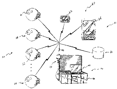
simultaneously
measure, record and transmit data on the physiological parameter(s) for all
players on the
team throughout the course of play, including a game or practice.
CA 02580318 2007-03-13
WO 2006/036567 PCT/US2005/032903
2
BACKGROUND OF THE INVENTION
[0004] Due to the physical nature of contact sports, such as football,
hockey, and lacrosse,
players receive a number of impacts during the course of play. The impacts
cause an
acceleration of the player's body part, including the head and brain.
[0005] Much remains unknown about the response of the brain to head
accelerations in the
linear and rotational directions and even less about the correspondence
between specific impact
forces and injury, particularly with respect to injuries caused by repeated
exposure to impact
forces of a lower level than those that result in a catastrophic injury or
fatality. Almost all of
what is known is derived from animal studies, studies of cadavers under
specific directional and
predictable forces (i.e. a head-on collision test), from crash dummies, from
human volunteers in
well-defined but limited impact exposures, or from other simplistic mechanical
models. The
conventional application of known forces and/or measurement of forces applied
to animals,
cadavers, crash dummies, and human volunteers limits our knowledge of a
relationship between
forces applied to a living human head and resultant severe and catastrophic
brain injury. These
prior studies have limited value as they typically relate to research in the
automobile safety area.
[0006] The concern for sports-related injuries, particularly to the head,
is higher than ever.
The Center for Disease Control and Prevention estimates that the incidence of
sports-related mild
traumatic brain injury (MTBI) approaches 300,000 annually in the United
States. Approximately
1/3 of these injuries occur in football. MTBI is a major source of lost player
time. Head injuries
accounted for 13.3% of all football injuries to boys and 4.4% of all soccer
injuries to both boys
and girls in a large study of high school sports injuries. Approximately
62,800 MTBI cases
occur annually among high school varsity athletes, with football accounting
for about 63% of
cases. Concussions in hockey affect 10% of the athletes and make up 12%-14% of
all injuries.
[0007] For example, a typical range of 4-6 concussions per year in a
football team of 90
players (7%), and 6 per year from a hockey team with 28 players (21%) is not
uncommon. In
rugby, concussion can affect as many as 40% of players on a team each year.
Concussions,
particularly when repeated multiple times, significantly threaten the long-
term health of the
athlete. The health care costs associated with MTBI in sports are estimated to
be in the hundreds
of millions of dollars annually. The National Center for Injury Prevention and
Control considers
sports-related traumatic brain injury (mild and severe) an important public
health problem
CA 02580318 2007-03-13
WO 2006/036567 PCT/US2005/032903
3
because of the high incidence of these injuries, the relative youth of those
being injured with
possible long term disability, and the danger of cumulative effects from
repeat incidences.
[0008] Athletes who suffer head impacts during a practice or game situation
often find it
difficult to assess the severity of the blow. Physicians, trainers, and
coaches utilize standard
neurological examinations and cognitive questioning to determine the relative
severity of the
impact and its effect on the athlete. Return to play decisions can be strongly
influenced by
parents and coaches who want a star player back on the field. Subsequent
impacts following an
initial concussion (MTBI) may be 4-6 times more likely to result in a second,
often more severe,
brain injury. Significant advances in the diagnosis, categorization, and post-
injury management
of concussions have led to the development of standardized tools such as the
Standardized
Assessment of Concussion (SAC), which includes guidelines for on-field
assessment and return
to sport criteria. Yet there are no objective biomechanical measures directly
related to the impact
used for diagnostic purposes. Critical clinical decisions are often made on
the field immediately
following the impact event, including whether an athlete can continue playing.
Data from the
actual event would provide additional objective data to augment psychometric
measures
currently used by the on-site medical practitioner.
[0009] Brain injury following impact occurs at the tissue and cellular
level, and is both
complex and not fully understood. Increased brain tissue strain, pressure
waves, and pressure
gradients within the skull have been linked with specific brain injury
mechanisms. Linear and
rotational head acceleration are input conditions during an impact. Both
direct and inertial (i.e.
whiplash) loading of the head result in linear and rotational head
acceleration. Head acceleration
induces strain patterns in brain tissue, which may cause injury. There is
significant controversy
regarding what biomechanical information is required to predict the likelihood
and severity of
MTBI. Direct measurement of brain dynamics during impact is extremely
difficult in humans.
[0010] Head acceleration, on the other hand, can be more readily measured;
its relationship
to severe brain injury has been postulated and tested for more than 50 years.
Both linear and
rotational acceleration of the head play an important role in producing
diffuse injuries to the
brain. The relative contributions of these accelerations to specific injury
mechanisms have not
been conclusively established. The numerous mechanisms theorized to result in
brain injury
have been evaluated in cadaveric and animal models, surrogate models, and
computer models.
Prospective clinical studies combining head impact biomechanics and clinical
outcomes have
CA 02580318 2007-03-13
WO 2006/036567 PCT/US2005/032903
4
been strongly urged. Validation of the various hypotheses and models linking
tissue and cellular
level parameters with MTBI in sports requires field data that directly
correlates specific
kinematic inputs with post-impact trauma in humans.
[0011] In the prior art, conventional devices have employed testing
approaches which do not
relate to devices which can be worn by living human beings, such as the use of
dummies. When
studying impact with dummies, they are typically secured to sleds with a known
acceleration and
impact velocity. The dummy head then impacts with a target, and the
accelerations experienced
by the head are recorded. Impact studies using cadavers are performed for
determining the
impact forces and pressures which cause skull fractures and catastrophic brain
injury.
[0012] There is a critical lack of information about what motions and
impact forces lead to
MTBI in sports. Previous research on football helmet impacts in actual game
situations yielded
helmet impact magnitudes as high as 530 G's for a duration of 60 msec and
>1000 G's for
unknown durations with no known MTBI. Accelerometers were held firmly to the
head via the
suspension mechanism in the helmet and with Velcro straps. A recent study
found maximum
helmet accelerations of 120 G's and 150 G's in a football player and hockey
player, respectively.
The disparity in maximum values among these limited data sets demonstrates the
need for
additional large-scale data collection.
[0013] Most prior art attempts relate to testing in a lab environment.
However, the playing
field is a more appropriate testing environment for accumulating data
regarding impact to the
head. A limitation of the prior art involves practical application and
widespread use of
measurement technologies that are size and cost effective-for individuals and
teams. Therefore,
there would be significant advantage to outfitting an entire playing team with
a recording system
for monitoring impact activities. This would assist in accumulating data of
all impacts to the
head, independent of severity level, to study the overall profile of head
impacts for a given sport.
Also, full-time head acceleration monitoring would also be of great assistance
in understanding a
particular impact or sequence of impacts to a player's head over time that may
have caused an
injury and to better treat that injury medically.
[0014] The present invention is provided to solve the problems discussed
above and other
problems, and to provide advantages and aspects not provided by prior systems
of this type. A
full discussion of the features and advantages of the present invention is
deferred to the
following detailed description, which proceeds with reference to the
accompanying drawings.
CA 02580318 2007-03-13
WO 2006/036567 PCT/US2005/032903
SUMMARY OF THE INVENTION
[0015] The present invention provides a multi-component system that
actively monitors at
least one physiological parameter of players engaged in a sporting activity.
The system includes
reporting units with a telemetry element that provide for the transmission of
each player's
physiological parameter data to a controller for calculation, recordation
and/or storage. The
reporting unit can be installed with each player's protective equipment. Since
most contact
sports involve multi-player teams, the system simultaneously measures, records
and transmits the
data on the physiological parameter(s) for all players on the team having a
reporting unit
throughout the course of play, including a game or practice. The system is
especially well suited
for helmeted team sports where players are susceptible to head impacts and
injuries; for example,
football, hockey, and lacrosse. Since the system can be employed with every
member of the
team, the system simultaneously measures, transmits and/or records impact
physiological data
from each player throughout the course of the practice or game.
[0016] According to an aspect of the present invention, the system actively
measures and
calculates the acceleration of a body part (e.g. the head) of players while
engaged in physical
activity, such as during play of a contact sport. When the calculated body
part acceleration
exceeds a predetermined level, a system controller transmits a signal to a
signaling device to
notify sideline personnel that a player(s) has experienced an elevated body
part acceleration. To
assist with future monitoring and evaluation, a system database stores the
calculated body part
acceleration for each player.
[0017] According to another aspect of the present invention, the system
actively measures
and calculates each player's body surface temperature during play. When the
calculated body
temperature exceeds a predetermined level, the system controller transmits a
signal to the
signaling device to notify sideline personnel that a player(s) has experienced
a significant body
temperature increase.
[0018] According to yet another aspect of the invention, the system
actively measures and
calculates the acceleration of each player's body part and the player's
temperature during play.
Thus, the system can actively monitor multiple physiological parameters for
each of the many
players engaged in physical activity.
[0019] Other features and advantages of the invention will be apparent from
the following
specification taken in conjunction with the following drawings.
CA 02580318 2007-03-13
WO 2006/036567 PCT/US2005/032903
6
BRIEF DESCRIPTION OF THE FIGURES
[0020] To understand the present invention, it will now be described by way
of example,
with reference to the accompanying figures in which:
Fig. 1 is a perspective view of the system of the invention, showing the
system
configured for use with football helmets;
Fig. 2 is a block diagram of the system of the invention;
Fig. 3 is a schematic of a reporter unit of the system of the invention; and,
Fig. 4 is a perspective view of a reporting unit of the system of the
invention, showing an
in-helmet version of the reporting unit.
DETAILED DESCRIPTION
[0021] Figs. 1 and 2, depict a multi-component system 10 for actively
monitoring a
physiological parameter of numerous players engaged in a sporting activity,
wherein the players'
data is transmitted to a controller for monitoring and recordation. In one
embodiment, the
system 10 is configured to measure and calculate the acceleration of a body
part (e.g., the head)
of players while engaged in physical activity, such as during play of a
contact sport. In another
embodiment, the system 10 is designed to measure and calculate each player's
body temperature
during play. In yet another embodiment, the system 10 is designed to measure
and calculate the
acceleration of each player's body part and the player's temperature during
play. Since most
contact sports involve multi-player teams, the system 10 simultaneously
measures, records and
transmits the data on the physiological parameter(s) for all players on the
team throughout the
course of play, including a game or practice. The system 10 is especially well
suited for
helmeted team sports where players are susceptible to head impacts and
injuries; for example,
football, hockey, and lacrosse. Therefore, the system 10 represents a platform
for actively
monitoring the physiological parameters of players engaged in sporting
activities. It is within the
scope of the invention for the system 10 to be configured to monitor a
physiological parameter of
a smaller number of players, meaning not all players engaged in the physical
activity.
[0022] The system 10 is generally comprised of multiple reporting units 20,
a controller unit
40, a signaling device 60, a database 80, and software 90 that enables the
various components of
the system 10 to communicate and interact. While the system 10 is described
below in the
context of a helmeted team sport, the system 10 can be utilized in connection
with other sporting
CA 02580318 2013-10-22
7
activities that do not require a helmet, such as soccer or rugby.
Consequently, the system 10
can be configured for use with other protective gear, such as a head band, leg
guard, or
shoulder pad. Because a football team includes numerous players, in some cases
exceeding
one hundred players, each player has a recording unit 20 that communicates
with the
controller 40. Therefore, the recording units 20 continuously and collectively
measure and
transmit physiological data to the controller for monitoring of the players.
While a
significant portion of the parameter measurement and monitoring occurs during
the course of
play, the system 10 continues to measure relevant physiological parameters,
such as the
players' body temperature, when players are at a reduced activity level on the
sideline.
[0023] The reporting unit 20 automatically and continuously measures and
records the
player's physiological parameters and transmits data regarding the parameter
to the controller
40. When the system 10 is configured for use with a football team, the
wearable reporting
unit 20 is adapted for use either within each player's helmet or protective
gear, such as
shoulder pads. Referring to Figs. 1-4, the reporting unit 20 includes a sensor
assembly
defined by a plurality of sensors 22 that measures the player's physiological
parameter and a
control unit 24, wherein the sensors 22 are operably connected to the control
unit 24. As
shown in Fig. 3, a wire lead 26 electrically connects each sensor 22 with the
control unit 24.
The control unit 24 can include a signal conditioner 24a, a filter 24b, a
microcontroller 24c
(or microprocessor), a telemetry element 24d, an encoder 24e, and a power
source 24f.
While the encoder 24e is shown as separate from the telemetry element 24d, the
encoder 24e
can be integrated within the telemetry element 24d. The sensors 22 are
calibrated to measure
the player's physiological condition or parameter and then generate input data
regarding each
parameter. The control unit 24 processes the input data, including filtering
and conditioning
as necessary, and then converts the data to signals. Next, the encoder 24e of
the control unit
24 encodes the signals with a unique identifier, and the telemetry element 24d
wirelessly
transmits (as represented by the lightening bolts in Fig. 1) the encoded
signals to the remote
controller 40 which recognizes the encoded signals for further processing and
calculation.
The telemetry element 24d can be a transceiver, or a separate receiver and
transmitter. The
power source 24f can be a rechargeable battery or a disposable battery. In
another
embodiment of the system 10, the parameter data transmitted from the reporters
20 to the
controller 40 can be encrypted to
CA 02580318 2007-03-13
WO 2006/036567 PCT/US2005/032903
8
increase the security of the underlying data. In this configuration, the
system 10 can include a
cipher for performing encryption and decryption, and a key to parameterize the
cipher.
[0024] The type of sensors 22 within the reporting unit 20 depend upon the
player's
physiological data to be measured, transmitted and monitored. For example,
when the reporting
unit 20 is configured to measure acceleration of the body part, the sensors 22
are single-axis
accelerometers, multi-axis accelerometers, or a combination of both. As
another example, to
measure the player's temperature, each reporting unit 20 includes at least one
sensor 22 such as a
thermistor, which comprises resistive circuit components having a high
negative temperature
coefficient of resistance so that the resistance decreases as the temperature
increases.
Alternatively, the temperature sensor 22 is a thermal ribbon sensor or a band-
gap type integrated
circuit sensor. To measure both the acceleration and temperature of the
player's body part, the
sensors 22 can be a combination of accelerometers and thermistors operably
connected to the
control unit 24. Where the system 10 is configured for use with a football
team to measure and
monitor head acceleration and player body temperature, the sensors 22 are
accelerometers and
thermistors that are arrayed in an in-helmet unit 28 (see Fig. 4) for each
player. To measure
other physiological parameters, such as the player's heart rate and blood
pressure the sensors 22
are micro electro-mechanical system (MEMS) type sensors that use auscultatory
and/or
oscillometric measurement techniques.
[0025] As shown in Fig. 4, the in-helmet unit 28 includes a flexible band
30 that houses the
sensors 22 and the control unit 24. The flexible band 30 is received within
the internal padding
assembly of the helmet 32, wherein the sensors 22 are positioned about the
player's skull. In this
manner, the in-helmet unit 28 is removably received within the helmet 32 to
allow for testing and
maintenance, including recharging of the battery power source. In one
embodiment where the
system 10 measures the acceleration of the player's head, the band 30 is
dimensioned such that
the sensitive axis of each accelerometer sensor 22 is orthogonal to the outer
surface of the
player's head. In another embodiment, the accelerometer sensors 22 are not
positioned
orthogonal to the head surface. Depending upon the other design parameters of
the system 10,
the accelerometer sensors 22 can be positioned either orthogonally or non-
orthogonally to each
other. While Fig. 3 depicts three sensors 22 within the control unit 20, the
precise number of
sensors 22 varies with the design of the system 10. In the embodiment where
the system 10
measures the player's temperature, the temperature sensor 22 can be placed
within the forehead
CA 02580318 2007-03-13
WO 2006/036567 PCT/US2005/032903
9
pad of the helmet 32 or at other locations in protective equipment, such as
shoulder pads, knee
pads, etc.
[0026] In operation, the reporting unit sensors 22 measure the
physiological parameter(s) and
generate signals in response to the measured parameter value. The sensors 22
can be configured
to continuously generate signals in response to the parameter value, or
generate signals only
when the parameter value reaches or exceeds a threshold level. For example,
the sensors 22 can
be single-axis accelerometers that measure head acceleration but only generate
signals when the
sensed head acceleration surpasses 10 G's. The control unit 24 processes the
data signals and
transmits them to the sideline controller 30 for calculation and monitoring of
the player's
physiological condition. As part of the processing step, the control unit 24
conditions and filters
the signals, as necessary, and then encodes the signals with a unique
identifier for transmission to
the controller 40. To support simultaneous transmissions from multiple
reporters 20 to the
correct controller 40, the signals sent from each control unit 24 can be
divided with time division
multiple access (TDMA), code division multiple access (CDMA), or frequency
division multiple
access (FDMA) technology. Encoding the signals with a unique identifier
enables the controller
40 to properly multiplex and decode information from the various reporters 20
transmitting data.
Accordingly, the system 10 simultaneously measures and transmits encoded data
from a number
of reporters 20 and then the controller 40 catalogs either the encoded data
signal for further
calculation, or the resultant calculation based upon the relationship between
the reporter 20 and
the player. Regardless of when the cataloging occurs, the controller 40
organizes each player's
calculated parameter result for further analysis and/or monitoring. In one
embodiment, an
operator of the system 10 defines the relationship or association between the
reporter 20 and the
player when the player is issued a helmet or protective gear having the
reporter 20. With the aid
of the signaling device 60, the sideline personnel utilizing the system 10 can
then monitor the
physiological condition of select players based upon the cataloging of the
calculated parameter
result.
[0027] The active monitoring system 10, including the reporting unit 20,
can be configured
to measure the severity of the impact upon the player's body part based upon
indirect measures
of the impact event. This indirect measurement is accomplished through
monitoring the
deformation experienced by the player's protective gear, including the helmet,
the shoulder pads,
and the internal padding assembly associated within each. An impact to a body
part may be
CA 02580318 2007-03-13
WO 2006/036567 PCT/US2005/032903
quantified by the body part's impact kinematics, which include a change in
position, change in
velocity and/or change in acceleration of the part over a select time
interval. In one embodiment,
small magnetic particles and at least one Hall-effect sensor are embedded
within the protective
equipment and/or the padding element connected to the equipment. The sensor
output is
dependent upon the distance between the particles and the sensor, wherein the
sensor output
measurements are applied to a rheologic model to calculate the impact force
experienced by the
equipment and/or pad element. For example, a mass-spring-damper model of the
padding
element and experimentally derived foam displacement and velocity values can
be utilized in the
model to estimate or calculate the impact acceleration and the magnitude of
the applied impact
force. A highly sensitive sensor array can be used to calibrate the protective
gear or padding
element to determine the location of the magnetic particles therein relative
to the Hall-effect
sensor(s). In another embodiment, the impact to the body part is measured and
calculated based
upon the change in shape or dimensions of the protective gear and/or the
padding element
connected thereto. Resistive sensing elements can be used where the resistance
in the
measurement device changes as a function of linear, torsional or shear
displacement.
Alternatively, capacitive sensing elements can be utilized where the
capacitance changes as a
function of linear, torsional or shear displacement. Shape-changing tape is an
example of the
sensing elements. In another embodiment of system 10, the reporting unit 20
includes a micro
electro-mechanical system (MEMS) pressure transducer that detects pressure
changes within an
enclosed fluid bladder or air chamber, such as those used with the padding
assembly of
protective sports equipment, such as helmets and shoulder pads. When the
protective equipment
to which the padding assembly is connected receives an impact force, the
padding assembly
compresses the fluid causing a pressure change that is measured by the MEMS
pressure
transducer. Since environmental conditions, including temperature and
humidity, affect the fluid
bladders and air chambers, the reporting unit 20 includes a temperature
compensation element to
improve the accuracy of the resulting measurements. In yet another embodiment
of the system
10, the reporting unit 20 measures the characteristic sound generated by an
impact to a body part
and/or the protective equipment overlying the body part. The system 10 employs
pattern
recognition to provide continuous evaluation of sounds resulting from impacts
in order to
characterize the severity of the impact on a scale. The software 100
associated with the pattern
recognition distinguishes impact-related sounds from ambient sounds typically
found at a
CA 02580318 2007-03-13
WO 2006/036567 PCT/US2005/032903
11
playing field, or selectively filters the ambient sounds so as to avoid
skewing the analysis and
results. The system 10 then categorizes the severity of the impact based upon
the characteristics
of the impact-related sound. One benefit of these approaches is that the
system 10 can positively
quantify the fit of the protective equipment or padding element with respect
to the player, and
provide an alert if there is an improper equipment fit.
[0028] Generally, the controller 40 receives the data measured and
transmitted by the
reporting units 20 and processes the data for meaningful analysis or use. The
sideline controller
40 is comprised of a portable microprocessor 42 (e.g., a laptop or portable
computer), including a
display screen, and a telemetry element 44 operably connected to the
microprocessor 42. The
controller 40 is a mobile apparatus that can be transported in a case 46.
Referring to Fig. 2, the
telemetry element 44 includes an antenna 48, a transmitter 50, a receiver 52
(or a combined
transceiver), and an encoder 54. Consistent with that explained above, the
telemetry element 44
decodes the encoded signals sent from each reporter 20, performs the requisite
calculation, and
then multiplexes the result according to the identity of the reporting unit
20. In this manner, the
controller 40 recognizes the identifier provided by each reporter 20 and
organizes the results for
each player having a reporter 20. The controller 40 has a local memory device
for storing data
received from the reporting units 20 and the subsequently calculated results.
Preferably, the
memory device of the controller 40 is capable of storing information compiled
over an entire
season, so if necessary, sideline personnel and/or medical staff can retrieve
historical player data
when needed. In preferred embodiments, the controller 40 can be equipped with
software 100
that includes team management information (e.g., complete roster list of
players, position of
players, identification of active players, etc.) and daily exposure
information (e.g., date, game vs.
practice, conditions, etc.). The controller 40 also is used to synchronize
local data (e.g., one
team or historical data) with the centralized database 80.
[0029] In operation, the controller 40 receives the encoded signal from the
reporting unit 20
for the measured physiological parameter (the "measured parameter") and
processes the data
within the signal to calculate a result for the parameter (the "parameter
result"). When the
parameter result reaches or exceeds a predetermined parameter level
(hereinafter the "alert
event"), the controller 40 communicates with the signaling device 60 thereby
alerting the sideline
personnel bearing the device 60. For each alert event, the controller 40
displays the affected
player's identity, for example by name or jersey number, the measured
parameter, and the time
CA 02580318 2007-03-13
WO 2006/036567 PCT/US2005/032903
12
of the alert event. However, the player's identity can be protected by use of
a unique player
identifier, which may be encoded or encrypted. When the parameter result falls
below the level
and an alert event does not occur, the controller 40 continues to receive data
from the reporters
20 and runs the requisite calculations. Further, when an alert event arises
from one reporter 20,
the controller 40 continues to receive and process data from the other
reporters 20. The time
stamp allows sideline personnel and medical staff to correlate the calculated
parameter to actual
videotape of the sporting event that led to the alert event. Once an alert
event has occurred, the
controller 40 sends a signal to the signaling device 60 that alerts the
sideline personnel to observe
and investigate the condition of the player in question. The player in
question is quickly
identified by the controller 40 due to the unique identifier provided by the
reporting units 20 and
the subsequent recognition of the identifier and the multiplexing performed by
the controller 40.
In this manner, the sideline personnel can efficiently evaluate the player at
issue from the many
players comprising the team.
[0030] As a further aspect of the operation of the system 10, the telemetry
element 44 of the
controller 40 can transmit a confirmation signal to each reporting unit 20
confirming that the
signals sent by that reporting unit 40 were successfully received and that the
data is complete for
calculation purposes. This enables the reporting units 20 to conserve power
since they do not
have to repeatedly send data to the controller 40. In the event that the
signals from a reporting
unit 20 are not successfully received or that the signals are incomplete or
skewed, the telemetry
element 44 transmits a resend signal that instructs the reporter 20 to resend
the signals from the
control unit 24 for reception by the controller 40. The reporter 20 can be
programmed to
automatically resend signals to the controller 40 in the situation where the
confirmation signal is
not received within a fixed period of time from the signal transmission by the
reporter 20. Since
numerous reporters 20 are simultaneously transmitting data signals during the
course of play, the
controller 40 is constantly assessing the quality of the transmitted signal
and sending the relevant
confirmation and resend signals to the various reporters 20.
[0031] In the embodiment where the system 10 measures player body part
acceleration, such
as head acceleration, when an alert event occurs, the controller 40 calculates
the point of impact
on the player's body part, the cumulative impacts sustained by the player
during the current
sporting session, and then graphs the magnitude and duration of recent impacts
to the player
and/or the body part. As part of this calculation, the controller 40 uses an
algorithm to estimate
CA 02580318 2007-03-13
WO 2006/036567 PCT/US2005/032903
13
the magnitude of the impact measured by the sensors 22, wherein the algorithm
comports with
the disclosure of co-pending U.S. Patent Application No. 10/997,832. As an
example, when the
system 10 measures and monitors the player's head acceleration, the controller
40 sends a signal
to a signaling device 60 when an impact magnitude exceeding a predetermined
threshold level
(e.g., 50 G's) is measured and calculated. When this alert event occurs, the
controller 40
calculates the point of impact on the player's head, the cumulative impacts
sustained by the
player during the current sporting session, and then graphs the magnitude and
duration of recent
head impacts for review by sideline personnel, including the training and
medical staff.
[0032] In the embodiment where the system 10 monitors each player's body
temperature, the
controller 40 receives data from the reporting units 20 and then calculates
each player's body
surface temperature, the rate of temperature increase and/or decrease versus a
selected time
interval. In addition to the temperature sensor 22 in the reporting unit 20,
the controller 40 can
include an additional temperature and/or humidity sensor to measure ambient
conditions and use
the resulting data for correction purposes. When the system 10 is configured
for player body
temperature monitoring in helmeted team sports, the reporting unit 20 can be
positioned within
the helmet 32 or within other protective equipment worn by each player, such
as a shoulder pad
assembly. The controller 40 receives the temperature data from each reporter
20 and then
applies an algorithm to calculate the player's body surface temperature, the
rate of temperature
increase and/or decrease, and other temperature-based parameters that aid in
the evaluation of
player thermal management.
[0033] As explained above, the signaling device 60 communicates with the
controller 40 and
alerts sideline personnel when a suspect event has occurred. The signaling
device 60 can be a
pager 62, a personal digital assistant (PDA) 64, or a portable electronic
device, such as a
telephone, that is capable of receiving data and displaying results
transmitted by the controller
40. Typically, the device 60 is worn or held by sideline personnel, including
the training staff,
medical personnel and/or coaches. Depending upon the parameters of the system
10, the
signaling device 60 could vibrate or sound an audio alarm when a suspect event
is measured and
recorded, and inform the wearer of the device 60 of the alert event. Regarding
the nature of the
alert event, the device 60 can advise of: the identity of player(s) affected;
the nature of the
suspect event, including an elevated head acceleration due to impact or a
change in a player's
physiological status such as elevated body temperature; and the time of the
incident.
CA 02580318 2007-03-13
WO 2006/036567 PCT/US2005/032903
14
[0034] In one embodiment, the PDA 64 is programmed with software 100 that
assures best
practices are followed in the treatment and documentation of mild traumatic
brain injuries
(MTBI). In another embodiment of the present invention, the PDA 64 software
100 includes a
bundle of team management programs which enables the PDA 64 to store all team
data,
including medical histories and testing baselines. The software 100 also
provides the PDA 64
with an active response protocol for guiding sideline personnel through
appropriate examination
procedures and recording the results. For example, when an alert event occurs
and the relevant
player is brought to the sideline for evaluation, the PDA 64 can display the
individual's head-
injury history, the results of previous evaluations and other pertinent
medical data. With the
assistance of the software 100, the PDA 64 prompts the medical staff member to
conduct the
appropriate sideline examination, records the responses, compares the results
to established
baselines and prompts either further. testing or a play/no-play decision. The
software 100 has a
bundle of team management tools that includes a roster program which contains
all the basic
information about each individual player: e.g., contact information, which
sports they play
(including position and jersey number), emergency information, relevant sizes,
equipment issues
and availability to play. Information can be stored and sorted in a variety of
ways, such as by
team, person item and size. The software 100 may also include a session
manager program that
allows the coaching staff to document incidents as they occur during a
practice or a game. The
appropriate information about the team, players and conditions is entered at
the beginning of
each session. Then, as injuries occur, the software 100 provides a template
for recording injury
data by player.
[0035] In another embodiment of the inventive system 10, the controller 40
is omitted and
the reporting units 20 interact and communicate directly with the signaling
device 60. In one
version of this embodiment, the reporting units 20 measure the physiological
parameters as
explained above and perform the related calculations within their control unit
24. All of the
calculated results are then transmitted from each reporting unit 20 to the
signaling device 60, for
example the PDA 64, for recordation and monitoring. The device 60 sorts and
multiplexes the
results while looking for an alert event. When the device 60 finds an alert
event, the device 60
alerts the sideline personnel consistent with that explained above.
Alternatively, each reporting
unit 20 performs the necessary calculations to arrive at a parameter result
and then transmits only
those results that amount to an alert event. In this manner, the device 60
receives signals from a
CA 02580318 2007-03-13
WO 2006/036567 PCT/US2005/032903
reduced number of reporters 20 and then alerts sideline personnel accordingly.
In another
version of this embodiment, the reporting units 20 measure the physiological
parameters and
transmit the data signals to the device 60, for example the PDA 64, wherein
the device 60
performs the related calculations to arrive at the parameter result. When the
parameter result
amounts to an alert event, the device 60 alerts the sideline personnel to
evaluate the player(s)
consistent with that explained above. To aid with the analysis of the
parameter results and the
subsequent player monitoring, the device 60 can be programmed with a bundle of
team
management software 100 which enable it to store all team data, including
medical histories and
testing baselines. The device 60 can also be programmed with an active
response protocol for
guiding sideline personnel through appropriate examination procedures and
recording the results.
The data and results stored on the device 60 can be uploaded to the database
80 wherein
authorized users can access same for team management and player evaluation
functions.
[0036] Referring to Figs. 1 and 2, in an embodiment of the present
invention, the system 10
includes a server 80, preferably a database server 80. The central database 80
stores data from
all remote sites, including information stored on the controller 40 and the
signaling device 60.
For example, the database 80 can serve as a team administrator database for
the athletic
department of a large university. That is, an interactive clearinghouse for
all athlete information
that needs to be shared among various departments or sports. The database 80
is internet enabled
to provide remote access to authorized users, including coaches, trainers,
equipment managers
and administrators, which allows the users to keep abreast of changes in
players' status. The
database 80 also provides a host of administrative and management tools for
team and equipment
staff.
[0037] To aid with the evaluation and monitoring of the players, the system
10 can be
configured to provide indicia of the impact force. Since the system 10
calculates the magnitude,
direction and time history of the impact causing the body part acceleration,
the system 10 can
quantify the severity of the impact on recognized scales, including the head
injury criteria (HIC)
and the severity index (SI) scales. Combining the data and/or the results into
correlative
measures may yield new indices that are more sensitive to the alert event. For
example, the
system 10 can utilize a combination of the measured parameter, the parameter
result and/or the
alert event to create a risk assessment index (RAI) for each player. The RAI
can be used for
team management purposes and future monitoring conducted by the system 10,
including
CA 02580318 2013-10-22
16
adjusting the sensitivity and operating parameters of the various components
of the system
10. In addition, the system 10 can be configured to provide diagnostic
functions from the
active monitoring of the players' physiological parameters, including the body
part
acceleration and body temperature calculations. Essentially, the system 10 can
utilize the
calculated results to provide diagnostic assistance to the sideline personnel
via either the
controller 40 or the signaling device 60. As part of the diagnostic
assessment, the system 10
weighs a number of factors including the player's medical and injury history,
the alert event,
and environmental factors.
[0038] In another embodiment of the present invention, the system 10 is
configured to
adjust its monitoring, sensitivity and/or calculations based upon the player's
recent medical
and injury history. Thus, the operational parameters and standards of the
system 10
components, including the reporting units 20, the controller 40 and the
signaling device 60,
can be adjusted for future monitoring of the players in light of each player's
recent data and
history. For example, the controller 40 can wirelessly communicate with the
reporting unit
20 to adjust the sensitivity of the sensors 22 for an individual player. In
this manner, there is
a feedback loop between the various components which can increase or decrease
the
sensitivity of the active monitoring performed by the system 10.
100391 While this invention is susceptible of embodiments in many different
forms, there
is shown in the drawings and herein described in detail preferred embodiments
of the
invention with the understanding that the present disclosure is to be
considered as an
exemplification of the principles of the invention and is not intended to
limit the broad
aspect of the invention to the embodiments illustrated.