Note : Les descriptions sont présentées dans la langue officielle dans laquelle elles ont été soumises.
CA 02580667 2007-03-15
WO 2006/031958 PCT/US2005/032906
SELF-SEALING MALE LUER CONNECTOR WITH
MOLDED ELASTOMERIC TIP
Background of the Invention
The present invention generally relates to medical connectors used in
conducting
medical fluids and more specifically to self-sealing male connectors.
The self-sealing medical connectors presently known and used in the art are
generally designed to be connected to a patient's intravenous ("IV") or gas
sampling line,
drug or solution source, or other medical device such that the connector's
seal operates to
trap all fluid on the side of the connector toward the patient or other
device. As such, the
typical connector has an unsealed male connector on one end that remains
connected to the
patient's IV line, fluid source or other device and a self-sealing female
connector on the
opposite free end of the connector through which a syringe or other such
device may be
engaged.
In use, the syringe or other device having a male connector is connected to
the
female end of the connector to push or pull fluids through the connector, as
when
medications are dispensed within a patient's IV line. The syringe or other
device is
configured with a male connector so as to engage the self-sealing female
connector and
cause the male connector's central boss to contact the female connector's seal
membrane,
opening an internal valve of the female connector and creating a fluid path
through the
connector. After the necessary fluids have been dispensed or withdrawn, the
syringe is
removed and the valve in the female needle-free connector closes to reseal the
female
connector and trap all bodily fluids, including any just-dispensed
medications, on the
patient side of the connector. However, the free end of the syringe and any
residual fluids
remaining therein are unsealed and exposed.
In the medical industry, there are applications in which the fluid being
dispensed
from or drawn into the syringe or other device or container must itself be at
all times
sealed off and exposure of the care giver to such fluid prevented or at least
minimized. For
example, in the area of nuclear medicine where radioactive isotopes are
administered to
patients, it is critical that exposure to the isotopes be minimized for the
safety of both the
care giver and the patient. A further example includes collecting blood from a
patient,
1
CA 02580667 2007-03-15
WO 2006/031958 PCT/US2005/032906
where it is important to prevent exposure of the blood remaining in the
collection device to
the care giver. For these purposes, a different self-sealing, needle-free Luer
connector
design is necessary.
Yet a further example is in the oncology area where certain drugs have great
beneficial effect when confined to the circulatory system of a patient, yet
are harmful to
the skin or other tissue of a patient. Such drugs must be carefully controlled
so that they
do not reach tissues that may be harmed. Transferring such drugs from one
container to
another or to the patient's fluid line can be hazardous if seals are not
present.
It is becoming more and more common for connectors to use Luer shapes. This is
because an international standard has been adopted for such shapes; see ISO
No. 594.
Such Luer shapes have a tapered outer surface for male connectors and a
complementary
tapered inner surface for female connectors. Such tapering permits connectors
having less
precise dimensions to still successfully mate for fluid transfer. For more
secure
connection, threads or thread elements have been added to the outer surface
surrounding
the female connector's opening and a threaded collar has been added about the
male Luer
connector. The threaded collar may freely rotate or may be fixed in position
about the
male Luer connector. Because of the wide availability of female connectors and
female
valve ports, it would be desirable to provide a self-sealing male connector
have a Luer
shape.
Therefore, a need exists in the art for a self-sealing male connector to seal
off
residual fluids therein before and after connection to a female Luer
connector. Such a self-
sealing male connector may be connected to a syringe or other device or formed
on a
blood collection device, or may be used with tubing or other devices for
controllably
conducting medical fluids, including more dangerous fluids that are toxic or
corrosive.
The present invention fulfills these needs and others.
Summary Of The Invention
Briefly and in general terms, the present invention is directed to a self-
sealing male
connector for needle-free connection with a female connector. The male
connector
includes a tubular male body configured on its distal end with an elastomeric
tip having a
transverse outer shape that differs from the female connector's inner shape,
and a size that
is greater than the inner size of the female connector. The tip is formed with
an aperture
2
CA 02580667 2012-02-29
and a hollow core in fluid communication with a flow passage formed in the
male body. In
use, when the male body is inserted within the female connector, the tip is
compressed and
sealingly conforms to the inside surface of the female connector, and the
aperture opens to
allow fluid flow through the male connector. When the male connector of the
present
invention is then withdrawn from the female connector, the resilient male tip
returns to its
uncompressed condition, thereby closing the aperture and sealing off any
residual fluids
within the male connector. In a further aspect, the aperture comprises a slit.
Accordingly, there is provided a self-sealing male connector for connecting to
a
female connector, the female connector having an internal flow passage with a
female
sealing surface having a transverse size and shape, the male connector
comprising: a tubular
male body having a distal end and a proximal end that are interconnected by an
internal flow
passage such that the ends are in fluid communication with one another within
the tubular
male body, and an elastomeric resilient tip disposed at the distal end of the
tubular male
body, wherein the elastomeric resilient tip comprises a male sealing surface
corresponding
to the female sealing surface, the male sealing surface having a transverse
outer size that is
greater than the corresponding female transverse size, and a transverse outer
shape that is
different from the corresponding female transverse shape, and the elastomeric
resilient tip
having an aperture; wherein the aperture is closed when the elastomeric tip is
in an
uncompressed condition, and the aperture is opened when the elastomeric tip is
in a
compressed condition.
In further aspects, the aperture comprises a slit and the shape of the
elastomeric tip is
selected such that the elastomeric tip reshapes to the compressed condition
when the female
connector is received onto the tubular male body so as to engage the tip with
the internal
flow passage, the aperture being responsive to the reshaping of the
elastomeric tip to the
compressed position to open and allow flow therethrough. Additionally, the
transverse shape
of the elastomeric tip is elliptical and defines a major axis and a minor
axis, the transverse
dimension is defined by the major axis, and the slit is disposed within the
elastomeric tip so
as to be substantially parallel to the major axis, whereby compressive forces
acting on the
transverse shape of the elastomeric tip upon insertion of the male body within
the flow
3
CA 02580667 2012-02-29
passage of the female connector are transmitted substantially along the major
axis causing
the slit to open.
In yet other aspects in accordance with the invention, the elastomeric tip
includes an
internal pressure resistance valve having a shape selected so that the
internal pressure
resistance valve tends to close the slit more tightly as a result of receiving
internal pressure
within the male connector. Additionally, the internal pressure resistance
valve having has a
shape selected so as to redirect fluid pressure within the tubular male body
against the slit to
tend to close the slit. Further, the pressure resistance valve comprises a
duckbill valve.
Further aspects include the material of the elastomeric tip being resilient so
that the
tip reshapes to the compressed condition upon insertion of the tubular male
body within the
female Luer connector and the tip conforms to and seals against the internal
flow passage of
the female connector, and the resilient material reshapes the elastomeric tip
to the
uncompressed condition when the tubular male body is withdrawn from the
internal flow
passage of the female connector so as to close the slit and reseal the flow
passage. The
elastomeric tip is formed as a separate component that is mounted to the
distal end of the
tubular male body. The elastomeric tip is bonded to the distal end of the
tubular male body.
The elastomeric tip is over-molded onto the distal end of the tubular male
body. The tubular
male body includes a distal annular flange forming an annular undercut, and
the elastomeric
tip includes a proximal annular flange to engage the annular undercut and to
secure the
elastomeric tip on the tubular male body.
In yet further aspects, the self-sealing male connector further comprises a
collar
disposed circumferentially about the tubular male body so as to form a
distally-opening
cavity, the collar formed with internal threads, wherein the female Luer
connector is
received within the distally-opening cavity to threadably connect the female
Luer connector
to the male Luer connector. Additionally, a blood collection device is
disposed on the
proximal end of the tubular male body and is in fluid communication with the
internal flow
passage of the male body. The transverse shape and size of the elastomeric
resilient tip are
selected so that the slit will close as soon as the male tip is withdrawn from
the flow passage
of the female connector.
4
CA 02580667 2012-02-29
In another aspect, there is provided a method of establishing a flow path for
fluid
between a male connector and a female connector having a female sealing
surface, the male
connector having a tubular male body with a distal tip, the method comprising:
inserting the
distal tip of the male connector into the female connector, the distal tip of
the male
connector being elastomeric and resilient and having a male sealing surface
corresponding
to the female sealing surface and having a transverse size and shape, wherein
the transverse
size is larger than the corresponding female sealing surface and the
transverse shape is
different from a transverse shape of the corresponding female sealing surface;
reshaping the
transverse shape of the male tip to the corresponding shape of the female
connector; opening
the male tip to establish a fluid passage through the male connector as a
result of the
reshaping step; withdrawing the distal tip of the male connector from the
female connector;
closing the male tip to prevent the flow of fluid through the male connector
as a result of the
withdrawing step.
In more detailed aspects of a method, the step of reshaping the male tip
comprises
compressing the male tip, the male tip being responsive to compressing to open
and allow
flow therethrough. Further, the step of compressing the male tip comprises
compressing the
male tip in a direction along a major axis of an elliptical transverse shape
of the male tip
with an aperture being formed in the male tip along the major axis so as to be
substantially
parallel to the major axis, whereby the compressive forces acting on the
transverse shape of
the elastomeric tip upon insertion of the male body within the flow passage of
the female
connector are transmitted substantially along the major axis causing the
aperture to open.
Additionally, the step of opening the male tip comprises opening a slit in the
male tip.
In other detailed aspects, the step of closing the male tip to prevent the
flow of fluid
through the male connector further comprises directing internal pressure of
the male
connector to close an aperture formed in the tip more tightly. Further the
step of reshaping
comprises reshaping the male tip to a compressed condition upon insertion
within the female
Luer connector so that the tip conforms to and seals against the female
connector and the
step of withdrawing the tip comprises expanding the tip to an uncompressed
condition at
which the tip is closed so as to prevent fluid flow.
5
CA 02580667 2012-02-29
In even more detailed aspects of the invention, the method further comprises
threadably engaging the male connector with the female connector. The method
further
comprises conducting fluid through the male connector in a direction away from
the female
connector, and collecting the conducted fluid in a blood collection device
disposed at a
proximal end of the male body.
These and other features and advantages of the present invention will become
apparent from the following detailed description of the preferred embodiments
which, taken
in conjunction with the accompanying drawings, illustrate by way of example
the principles
of the invention.
5a
CA 02580667 2007-03-15
WO 2006/031958 PCT/US2005/032906
Brief Description of the Drawings
FIGURE 1 is a simplified pictorial illustration of a patient IV administration
set in
connection with an exemplary embodiment of a self-sealing male Luer connector
in
accordance with the present invention that has been mounted to a syringe;
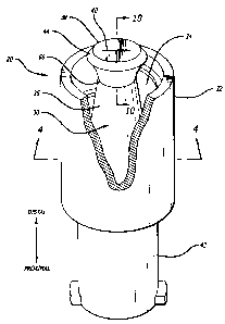
FIG. 2 is a perspective view, partially in section, of one embodiment of the
self-
sealing male Luer connector, including a tubular male body configured at its
distal end
with an elastomeric tip, a threaded collar located about the male Luer
connector, and a
proximal female connector device;
FIG. 3 is an enlarged top view of the distal end of the male Luer connector of
FIG.
2;
FIG. 4 is a partial cross-sectional view of the male Luer connector of FIG. 2
taken
along line 4-4, also partially showing an adjacent self-sealing female Luer
connector in
section prior to its engagement with the male Luer connector;
FIG. 5 is a view the same as FIG. 4 except that the female Luer connector has
begun to engage the male Luer connector;
FIG. 6 is a top view of the engagement of the female and male connectors as in
FIG. 5 along lines 6 -- 6 with the female Luer connector's self-sealing piston
removed for
simplicity, showing the circular opening in the female connector in solid
lines and the
elliptical shape of the male tip in dashed lines and the elastomeric male tip
just engaging
the female Luer connector and the slit in the male tip remaining closed;
FIG. 7 is another partial cross-sectional view of the engagement of the female
and
male Luer connectors shown in FIGS. 4 and 5 with the female and male Luer
connectors
fully engaged so that the elastomeric tip of the male connector has been
compressed and
the fluid flow slit is open;
FIG. 8 is a top view similar to the view of FIG. 6 but along lines 8 -- 8 of
FIG. 7,
with the female Luer connector's self-sealing piston removed for simplicity,
showing the
elastomeric male tip conforming to the circular shape of the female Luer
connector and the
slit in the male tip opened;
6
CA 02580667 2007-03-15
WO 2006/031958 PCT/US2005/032906
FIG. 9 is an enlarged partial cross-sectional view of the elastomeric tip of
the male
Luer connector of FIG. 2;
FIG. 10 is an enlarged partial cross-sectional view of the elastomeric tip of
the
male Luer connector of FIG. 9 rotated by ninety degrees, showing a duckbill-
type valve
structure disposed internally to the tip;
FIG. 11 is an enlarged partial cross-sectional view of an alternative
embodiment
male body and elastomeric tip configuration; and
FIG. 12 is a perspective view, partially in section, of an alternative
embodiment of
a self-sealing male Luer connector, including a tubular male body configured
at its distal
end with an elastomeric tip, a threaded collar, and a proximal blood
collection device.
Detailed Description of the Preferred Embodiments
Referring now to the drawings in more detail, wherein like reference numerals
designate corresponding or like elements among the several views, there is
shown in FIG.
1 a self-sealing male Luer connector 20 in accordance with aspects of the
present
invention. In this embodiment, the male Luer connector is mounted at the
distal end of a
syringe 22 and operably connected to the proximal end of a female Luer
connector 24
configured on a Y-site 26 for the administration or withdrawal of fluids
through the I.V.
line 28. It should be noted that for purposes of convenience in reference,
"distal" is meant
to refer to the direction toward the patient and "proximal" is meant to refer
to the direction
away from the patient, or toward the syringe or other collection or dispensing
device.
Referring to FIG. 2, there is shown a perspective view, partially in section,
of an
embodiment of the self-sealing male Luer connector 20 in accordance with
aspects of the
present invention. The male Luer connector includes a tubular male body 30 and
an outer
collar 32 located circumferentially thereabout to form a cavity 34 at the
distal end of the
male body. The open cavity is configured for receipt of the female Luer
connector. The
male body also includes an exterior surface 36 that is tapered to a smaller
diameter in the
distal direction in accordance with Luer standards, in this embodiment. An
elastomeric tip
38 having an aperture 40, in this embodiment a slit 40, for selectively
allowing flow
through the male Luer connector is connected to the distal end of the male
body. A
conventional female connector device 42 is shown as being configured at the
proximal end
7
CA 02580667 2007-03-15
WO 2006/031958 PCT/US2005/032906
of the male Luer connector, though it will be appreciated that a variety of
other connectors
and devices, such as a shielded blood collection cannula device may be
employed without
departing from the scope of the present invention. In one embodiment, the self-
sealing
male Luer connector can be mounted on a syringe in the typical fashion by
screwing the
proximal female connector device onto the distal end of the syringe. The
elastomeric tip
of the male connector will remain in its at-rest, uncompressed position
keeping the slit
closed and thereby sealing off the flow passage and preventing the unwanted
escape of any
fluid from within the syringe.
Referring still to FIG. 2, it can be seen that the elastomeric tip 38 includes
a
transverse outer shape and size 44 that is oversized relative to the distally-
tapered exterior
surface 36 of the male body. Because the exterior surface is configured to
engage the
interior surface of the female Luer connector 26 when the connectors are
mated, it follows
that the transverse shape and size of the elastomeric male tip are also
oversized relative to
the interior cross-section of a female Luer connector. On this basis, it will
be appreciated
that as the female Luer connector is inserted onto the male body 30 and
advanced in the
proximal direction, the elastomeric tip will be compressed within the female
Luer
connector and reshaped to cause the tip to sealingly conform to the interior
surface of the
female connector and the slit of the male tip will open and allow flow through
the male
body. The self-sealing male Luer connector 20 will close and prevent flow
therethrough
when disconnected from a female connector, or the like, while it opens and
allows flow
during proper connection with a female connector. When withdrawn, the
elastomeric and
resilient tip 38 will naturally return to its original shape at which the slit
40 is closed to
prevent fluid flow therethrough. It will be appreciated by those skilled in
the art that the
male Luer connector of the present invention is configured to be both self-
sealing and to
allow needle free connection to a female Luer connector, thereby protecting
both the care
giver and the patient from dangerous cross-contamination before, during, and
after use.
FIG. 3 is an enlarged top view of the male Luer connector 20 showing the
transverse outer shape 44 of the elastomeric tip 38. In the embodiment shown,
the shape is
elliptical so as to have a major axis 46 and a minor axis 48. The major axis
defines the
largest transverse dimension across the tip, which is larger than the circular
opening of the
typical female Luer connector, as discussed above and explained more fully
below in
conjunction with FIGS. 4 through 8. In this way, as the male body 30 is
received within
8
CA 02580667 2007-03-15
WO 2006/031958 PCT/US2005/032906
the female Luer connector and the compressive forces generated as a result of
the
interference between the transverse shape and size of the tip and the interior
surface of the
female Luer connector are transmitted substantially along the major axis, or
generally
normal to the engaging surfaces through which the compressive forces are
transmitted. As
shown, the slit 40 formed within the elastomeric tip is substantially parallel
to the major
axis of the elliptical tip so that the compressive forces transmitted along
the major axis
when the male and female Luer connectors are connected essentially act on each
end of the
slit parallel to the slit's own central axis to compress the slit lengthwise
and cause it to
open centrally and allow flow therethrough. This compression and opening will
be shown
and described below in FIGS. 7 and 8.
Turning now to FIG. 4, there is shown a cross-sectional view of the embodiment
of
a self-sealing male Luer connector 20 of FIG. 2. As best shown in this view,
the tubular
male body 30 is formed along its length between its distal end 50 and its
proximal end 52
with an internal flow passage 54. The elastomeric tip 38 is formed with a
central, hollow
core 56 configured to be in fluid communication between the slit 40 of the tip
and the flow
passage of the male body when the tip is mounted on the male body's distal end
as shown.
At the proximal end of the male body, the female connector device 42 is formed
so as to be
integral with the male body and to allow for fluid communication between an
internal bore
or flow passage 58 of the female connector device and the internal flow
passage 54 of the
body 30. In this way, a complete fluid flow path is formed between the female
connector
device and any medical device to which the female connector device is
connected, such as
the syringe 22, and the slit in the distal elastomeric tip.
With continued reference to FIG. 4, the annular male collar 32 has an interior
surface 60 that may be configured with internal threads 62 for threadable
engagement with
external thread portions 64 formed on the proximal end of the female Luer
connector so as
to secure the female Luer connector 24 onto the male Luer connector 20 during
connection. In the embodiment shown, the collar is integral with both the
tubular male
body and the female connector device 42 at a mid-section annular joint 68.
However,
other arrangements for mounting the collar may be used.
It will be appreciated by those skilled in the art that the unitary
construction of the
tubular male body 30, collar 32, and female connector device 42 of the male
Luer
connector 20 shown in FIGS. 2 and 4 is well-suited for the injection molding
9
CA 02580667 2007-03-15
WO 2006/031958 PCT/US2005/032906
manufacturing process, whereby the complete unit may be made together in a
relatively
simple two-half mold cavity with two coaxial core pulls. Because the design of
the male
Luer connector is particularly suited to injection molding, it may be formed
from a variety
of thermoplastic materials such as polyethylene, polypropylene, polycarbonate,
PVC,
ABS, acrylic, and K-resin. As such, the male Luer connector shown in the
embodiments
may be readily manufactured with no moving parts. While a particular
configuration of
the male body, collar, and female connector device has been shown and
described, it will
be appreciated that various other configurations whereby one or more of the
components
may be molded separately and subsequently assembled together using a solvent-
bonding,
snap- or interference-fit, ultrasonic welding, or other such assembly process
now known or
later developed may be employed without departing from the scope of the
present
invention.
The female Luer connector 24, such as that found at a patient's Y-site 26,
shown
adjacent the distal end of the male Luer connector 20 in FIG. 4 is generally
configured
with a tubular barrel 70 having a tapered interior surface 72 formed according
to
ANSI/AAMUISO standard 594.1 for medical connectors. As such, the opening 78
and
cross sectional shape of the interior surface 72 is circular. A self-sealing
piston 74 may be
installed within the tubular barrel having a selectively openable opening 76
responsive to
compression of the piston upon insertion of a male Luer connector to open the
opening and
allow fluid flow through the female Luer connector. As mentioned above and
discussed
more fully below regarding FIGS. 7 and 8, the distally-tapered exterior
surface of the
tubular male body 30 is configured to sealingly engage the tapered inside
surface 36 of the
female Luer connector when the two connectors are mated. It will be
appreciated by those
skilled in the art, however, that other female Luer connector configurations,
such as those
self-sealing female connectors that have a straight-wall, rather than tapered,
internal bore,
may be employed in the art, in which case the exterior surface of the male
body need not
itself be distally-tapered and a seal between the connectors may be achieved
through the
elastomeric tip, as discussed below.
Turning, now to FIG. 5, the male and female connectors have been moved closer
together and there is shown a cross-sectional view of the self-sealing male
Luer connector
20 with the female Luer connector 24 partially inserted thereon. As shown, the
tubular
barrel 70 of the female Luer connector has been advanced toward the male body
30 so as
CA 02580667 2007-03-15
WO 2006/031958 PCT/US2005/032906
to just engage the elastomeric tip 38 with the circular opening 78 formed at
the proximal
end of the tapered interior surface 72 of the tubular barrel. In this
position, the tip
effectively makes an edge seal against the opening, but has not yet advanced
sufficiently
within the tubular barrel to cause the tip to be compressed and its slit 40 to
be opened.
Similarly, while the tip has just begun to flex, the self-sealing internal
piston 74 of the
female Luer connector is in the position of initial engagement and the piston
has not yet
been displaced far enough to open the opening 76 within the piston.
As best shown in the partial cross-section top view of FIG. 6 with the self-
sealing
piston 74 of the female connector 24 removed for clarity, the elliptical
transverse outer
shape 44 (dashed lines) of the elastomeric tip 38 remains unaltered and
oversized relative
to the circular opening 78 of the tubular barrel 70 of the female connector as
a distal tip
wall 80 of the male elastomeric tip seats thereon. Specifically, the major
axis 46 (FIG. 3)
of the elliptical transverse shape defines the largest transverse dimension
across the shape,
or the length of the ellipse, which is greater than the dimension across the
opening 78 of
the female connector tubular barrel, as shown. Likewise, the minor axis 48
(FIG. 3) of the
elliptical transverse shape defines the width of the ellipse so as to be
substantially
equivalent to or slightly larger than the annular shape, such that the entire
transverse shape
engages the opening 78 of the female connector to create the edge seal.
Therefore, it will be appreciated by those skilled in the art that the male
Luer
connector 20 is so configured that upon initial engagement with a self-sealing
female Luer
connector 24, the two connectors begin to form a seal between the elastomeric
tip 38 of the
male body 30 and the opening 78 of the tubular barrel 70 of the female
connector before
any fluid flow through the male Luer connector is allowed. Hence, the male
Luer
connector of the present invention provides for safe and effective needle free
connection to
a self-sealing female Luer connector with minimized risk of fluid escape by
creating a seal
between the connectors before each is activated through further proximal
movement of the
female Luer connector.
Turning now to FIG. 7, there is shown a partial cross-sectional view of the
female
Luer connector 24 fully inserted onto the self-sealing male Luer connector 20.
As such,
the tapered exterior surface 36 of the tubular male body 30 has been brought
into
engagement with the tapered interior surface 72 of the female Luer connector's
tubular
barrel 70. Furthermore, the external thread portions 64 formed on the proximal
end of the
11
CA 02580667 2007-03-15
WO 2006/031958 PCT/US2005/032906
female connector tubular barrel have threadably engaged the internal threads
62 of the
male collar 32 to secure the connection of the female Luer connector onto the
male Luer
connector. While it will be appreciated by those skilled in the art that the
interference
surface-to-surface fit between the respective tapered surfaces of the male and
female Luer
connectors may be sufficient to maintain connection between them during use,
this means
alone of securing the connection is not widely practiced, and the
precautionary measure of
threading the connectors together as described and shown is preferred. It is
to be
understood, however, that numerous other connection means now known and later
developed in the art for securing male and female Luer connectors in
engagement may be
employed without departing from the scope of the present invention. Even where
a
threaded collar is employed, it will be appreciated that the collar may, for
example, be a
separate component snap-fit onto the male body so as to swivel rather than the
rigid
attachment shown in the exemplary embodiment.
Returning again to FIG. 7 and also referring to FIG. 8, with the male Luer
connector 20 and the female Luer connector 24 fully engaged along their
respective
tapered surfaces, the elastomeric tip 38 disposed at the distal end of the
tubular male body
30 is shifted to its compressed position or condition within the tubular
barrel 70 of the
female Luer connector thereby opening the slit 40 and allowing fluid flow
through the
male Luer connector. In this compressed configuration, the tip conforms to and
seals
against the inside surface 72 of the tubular barrel of the female connector
such that the
transverse outer shape 44 of the tip takes on the circular shape corresponding
to the inside
surface of the barrel. In this embodiment, the elastomeric tip is essentially
pressed into a
frusto-conical shape when in the compressed condition. Again, the resulting
radially-
inward compression of the tip substantially along its major axis 46 also
causes the slit to
open centrally as best shown in FIG. 8. It will be appreciated by those
skilled in the art
that in order for the tip to sealingly conform to the inside surface of the
tubular barrel and
selectively open and close the slit, the tip is to be made of a resilient
material, such as
silicon rubber, thermoplastic elastomer, or thermoplastic vulcanate. It
follows that the
elastomeric tip is also well-suited for an injection molding manufacturing
process. The slit
30. feature may also be molded or may be formed in a subsequent step using a
knife blade
cutting process or the like. It will also be appreciated that various other
materials and
methods of manufacture now known or later developed in the art may be employed
without departing from the scope of the invention.
12
CA 02580667 2007-03-15
WO 2006/031958 PCT/US2005/032906
Referring to FIG. 7, the distal projection of the male body 30 and the tip 38
of the
self-sealing male Luer connector 20 within the tubular barrel 70 also serves
to displace and
activate the piston 74 of the female Luer connector 24 to allow fluid flow
therethrough.
Thus, with both the self-sealing piston of the female Luer connector and the
elastomeric tip
of the male Luer connector activated, a fluid flow path is now formed through
both
connectors as shown by flow arrows 82. In one embodiment in which the female
connector device 42 formed at the proximal end of the male Luer connector is
mounted on
a syringe and then connected distally to a patient's I.V. interface so as to
withdraw fluids,
the fluid will flow through the piston 74 of the female connector and its
proximal opening
76, the slit 40 and the hollow core 56 of the male elastomeric tip, the flow
passage 54 of
the male body, and the internal bore 58 of the female connector device into
the syringe.
The same flow path would be followed in reverse if medicines or other fluids
are being
dispensed from the syringe into the patient's I.V. line.
In either case, once the desired quantity of fluids has been withdrawn into or
dispensed from the syringe, the male Luer connector may then simply be
withdrawn and
disconnected from the female Luer connector, whereby the respective self-
sealing devices
would then reseal. Regarding the male Luer connector of the present invention,
it will be
appreciated that the resilient elastomeric tip will shift to its at-rest,
uncompressed position
or condition upon withdrawal and disconnection from the female Luer connector
so as to
reseal its slit and close the flow passage. Because the slit effectively
reseals before or just
as the edge seal formed between the tip and the opening 78 of the female
connector tubular
barrel is disengaged, the self-sealing male Luer connector is again closed
before the
engagement is lost, whereby any residual fluid in the syringe is effectively
trapped on the
syringe side by the male tip and unwanted fluid escape and unnecessary risks
of exposure
and cross-contamination to the care giver and the patient are prevented. It
will be further
appreciated that the male Luer connector is easy to wipe and keep sanitary, as
all
engagement surfaces are exposed and easily accessible upon disconnection from
the
female connector.
It should also be noted that an elastomeric male tip 38 having dimensions that
exceed the opening 78 of the female barrel 70 in all directions may not be
necessary in all
embodiments. For example, the major axis 46 of the elastomeric male tip may
exceed the
diameter 72 of the opening of the female barrel but the minor axis 48 may not.
In such a
13
CA 02580667 2007-03-15
WO 2006/031958 PCT/US2005/032906
case, an edge seal may not occur when the elastomeric male tip and the female
opening are
first brought together. However, once the elastomeric male tip has been moved
into the
female barrel, the male tip is forced into the shape of the female interior 72
to thereby
provide a seal. However, such an embodiment may work well where the timing of
the shut
off of the female valve is such that the female valve completely closes prior
to the
elastomeric male tip leaving the female opening and resuming its elliptical
shape. With
such timing, the female valve closes before the elastomeric tip completely
leaves the
female barrel and the elastomeric male tip self closes as soon as it leaves
the opening of
the female barrel 70 or as it is leaving. Thus, a very desirable effect is
achieved in that
both connectors close upon disconnection.
Relatedly, because the engagement surfaces are accessible, particularly the
elastomeric tip 38 as best shown in FIG. 4, those skilled in the art will
appreciate that the
male Luer connector 20 of the present invention can be primed before use by
squeezing the
tip about the major axis 46 to temporarily open the slit 40 so as to remove
air pockets or
other dead spaces within the connector or equalize the pressure across the
tip. This step is
particularly beneficial where fluids are being introduced from a syringe 22 or
other
dispensing device through the male Luer connector into a patient's I.V. line
28, wherein
the introduction of air into the line may cause medical complications for the
patient.
Turning now to FIGS. 9 and 10, there are shown enlarged partial cross-
sectional
views of the distal end of the tubular male body 30 with the elastomeric tip
38 installed
thereon. As a flush mount configuration wherein the substantially planar
proximally-
facing surface of the tip 66 is to be installed on the corresponding
substantially planar
distally-facing surface 50 of the male body, it will be appreciated that a
solvent-bonding
assembly method may be employed in one embodiment to secure the tip on the
male body.
It will be further appreciated that numerous other assembly techniques may be
employed,
such as the over-molding alternative embodiment of FIG. 11, discussed below.
The
hollow core 56 of the tip is configured so that with the tip mounted flush on
the distal end
50 of the body, the base 84 of the core 56 is substantially equivalent to and
centered on a
tapered interior surface 86 of the male body. In this way, a smooth transition
is formed
between the flow passage 54 and the core 56 so that there are no dead spaces
within the
flow path and the flow therethrough is more laminar than turbulent.
14
CA 02580667 2007-03-15
WO 2006/031958 PCT/US2005/032906
Similarly, a proximal outer surface 88 of the tip is configured to have a
cross-
section substantially equivalent to the tapered outer surface 36 of the male
body at the
distal end to produce a smooth transition between the tip and the body.
Referring back to
FIG. 7, which shows the female Luer connector 24 fully inserted onto the male
Luer
connector 20, it will be appreciated by those skilled in the art that the
smooth transition
between the tip and the male body facilitates the shifting of the tip so as to
conform to the
inside surface 72 of the tubular barrel 70 of the female connector, whereby
the tip takes on
the frusto-conical shape described above and essentially becomes a
continuation of the
tapered outside surface of the male body in sealingly engaging the female Luer
connector.
As best shown in FIG. 9, in one embodiment of the present invention, the
hollow
core 56 of the male elastomeric tip 38 is configured to open at the proximal
end 66 of the
tip at the tip's base 84 and extend toward, but terminate short of, the distal
wall 80 of the
tip. In this case, the tip includes a duckbill-type valve 130 to assist in
preventing leakage
of fluid through the tip due to high internal pressures. The duckbill valve is
better seen in
FIG. 10, which is a side cross-sectional view of the tubular male body 30 and
the
elastomeric tip 38 similar to that of FIG. 9 but rotated by ninety degrees.
The lips 132 and
134 of the duckbill valve are shown and between them contain the slit 40.
Duckbill valves
are well known to those skilled in the art. The open spaces 136 and 138
adjacent the lips
allow for the presence of fluid under pressure. That fluid will apply inward
pressure to the
lips forcing them together and more tightly closing the slit 40. However, this
is only one
embodiment and in other embodiments, a different valve may be used, or no
valve at all.
Turning to FIG. 11, there is shown an enlarged cross-sectional view of an
alternative embodiment tubular male body 100 and elastomeric tip 102. The
distal end 104
of the male body is configured with a radially-outwardly-extending annular
flange 106 so
as to form an annular undercut 108. With the distal end of the male body so
configured, it
will be appreciated that the elastomeric tip can then be over-molded onto the
body through
a molding technique known and used in the art. Hence, the proximal end of the
tip may be
formed so as to have an inwardly-projecting annular flange 110 that seats
within the
undercut to secure the tip in position on the male body. In the embodiment
shown, the tip
itself and the hollow core 112 are formed as in the embodiment of FIGS. 2-10.
As such,
the core essentially continues the taper from an inside surface 114 of the
male body so that
a single core pull from the proximal end of the male body is possible in
forming both the
CA 02580667 2007-03-15
WO 2006/031958 PCT/US2005/032906
body and the internal features of the elastomeric tip. Those skilled in the
art will also
appreciate that the male body and tip may be formed in separate molding
operations and
assembled as shown and described in a subsequent step through a snap-fit,
solvent bond or
both, or using other assembly techniques now known or later developed in the
art. As also
shown, the outwardly-extending annular flange 106 may be configured having an
outside
dimension that is smaller than that of the male body's outside surface 116 so
that when the
tip is molded or otherwise installed on the male body, the tip's proximal
outside surface
118 makes a smooth transition to the male body's outside surface, which,
again, facilitates
sealingly conforming the elastomeric tip to the female Luer connector's inside
surface
during connection.
Referring now to FIG. 12, there is shown an alternative embodiment of a male
Luer
connector 120 having a blood collection device 122 mounted opposite the
tubular male
body 30, rather than a conventional female Luer connector. The blood
collection device,
which is known and used in the art, includes a proximally-extending sharpened
cannula
124 and a shield 126 mounted about the needle so as to protect care givers and
patients
from accidental needle punctures. So configured, the connector's male body may
be
connected to the female Luer connector of a Y-site or other device in a
patient's IV line, as
discussed above, to compress the elastomeric tip 38 and open the slit 40,
thereby creating a
flow path between the patient's I.V. line and the needle through the flow
passage of the
male Luer connector. As is known in the art, a resilient boot (not shown) over
the
sharpened needle 124 can be used to prevent the flow of fluid through the
needle until a
vacuumized blood collection vial with septum (not shown) is inserted within
the blood
collection device shield to push the boot up the needle while the needle then
penetrates the
septum to allow fluid to flow therethrough into the vial. When the vial is
full, it may be
removed from the blood collection device and another installed therein until
the desired
quantity of blood has been withdrawn. Then, the male connector may simply be
disconnected from the female connector on the patient's I.V. line and
discarded. From the
foregoing, it will be appreciated that upon disconnection, the resilient
elastomeric tip 38
expands to its uncompressed condition to reseal the slit and trap all blood
and other fluids
within the male Luer connector for safe disposal. Thus, in this embodiment of
the present
invention, as with the exemplary embodiment including a conventional female
connector,
the male Luer connector formed with a self-sealing elastomeric tip operably
installed on
the distal end of the tubular male body serves to safely and easily connect to
and
16
CA 02580667 2007-03-15
WO 2006/031958 PCT/US2005/032906
disconnect from the female Luer connector of a patient's I.V. line for the
effective and
controlled administration and/or withdrawal of fluids. Therefore, the male
self-sealing or
"valved" Luer connector of the present invention is well-suited for connection
to a syringe
or other device used to transfer fluids to and from a patient without
compromising the
patient's or the care giver's safety.
While particular forms of the invention have been illustrated and described,
it will
also be apparent to those skilled in the art that various modifications can be
made without
departing from the spirit and scope of the invention. Accordingly, it is not
intended that
the invention be limited except by the appended claims.
17