Note : Les descriptions sont présentées dans la langue officielle dans laquelle elles ont été soumises.
CA 02580963 2007-03-20
WO 2006/036759 PCT/US2005/034048
1
METHOD AND APPARATUS FOR COMMUNICATION
IN A SYSTEM EMPLOYING DIFFERING
TRANSMISSION PROTOCOLS
Claim of Priority under 35 U.S.C. 119
[0001] This application claims priority to U.S. Provisional Application No.
60/612,679
filed September 24, 2004, entitled "OFDM Pilot Structure for TDM Overlaid
Systems,"
and assigned to the assignee hereof and hereby expressly incorporated by
reference
herein.
BACKGROUND
Field
[0002] The present invention relates generally to communication systems, and
more
specifically, to a method and apparatus for communication in a wireless
communication
system employing differing transmission protocols.
Background
[0003] Wireless communication technologies have seen explosive growth over the
past
few years. This growth has been primarily fueled by wireless services
providing
freedom of movement to the communicating public as opposed to being "tethered"
to a
hard-wired communication system. It has also been fueled by the increasing
quality and
speed of voice and data communications over the wireless medium, among other
factors. As a result of these enhancements in the communications field,
wireless
communications has had, and will continue to have, a significant impact on a
growing
number of the conununicating public.
[0004] Wireless communication systems are widely deployed to provide various
communication services such as voice, packet data, multi-media broadcast, text
messaging, and so on. These systems may be multiple-access systems capable of
supporting communication for multiple users by sharing the available system
resources.
Examples of such multiple-access systems include Code Division Multiple Access
(CDMA) systems, Time Division Multiple Access (TDMA) systems, Frequency
Division Multiple Access (FDMA) systems, and Orthogonal Frequency Division
Multiple Access (OFDMA) systems. A CDMA system may implement a radio access
CA 02580963 2007-03-20
WO 2006/036759 PCT/US2005/034048
2
technology (RAT) such as Wideband CDMA (W-CDMA), cdma2000, and so on. RAT
refers to the technology used for over-the-air communication. W-CDMA is
described
in documents from a consortium named "3rd Generation Partnership Project"
(3GPP).
cdma2000 is described in documents from a consortium named "3rd Generation
Partnership Project 2" (3GPP2). 3GPP and 3GPP2 documents are publicly
available.
[0005] Communication performed within the wireless communication system may be
accomplished via a unicast transmission and/or via a broadcast transmission
through an
Enhanced Multimedia Broadcast/Multicast Communication Service (E-MBMS) in a
time division multiplex (TDM) slotted mode, for example. A unicast
transmission is
defined as a communication that is transmitted from one single point to
another single
point (e.g., from one transmitter to one receiver); whereas a broadcast
transmission is
defined as a communication that is transmitted from one point to multiple
other points
(e.g., from one transmitter to multiple receivers).
[0006] When performing channel estimation in a receiver for coherent
demodulation,
typically the pilots present in the one or two symbols occurring prior to and
the one or
two symbols occurring after the symbol being analyzed for channel estimation
are also
analyzed to provide for a more accurate channel estimation. Accordingly, the
channel
estimation is performed by averaging the analysis of the pilots over three to
five
symbols (i.e., the symbol under analysis and the one or two symbols preceding
and one
or two symbols following the symbol under analysis). However, the effective
delay
spread of a single frequency network (SFN) broadcast channel is much larger
than a
unicast channel and the required number of FDM pilot tones increases as the
delay
spread of the channel increases. Accordingly, because the number of pilot
tones used
for a broadcast transmission is much greater than the number of pilot tones
used for a
unicast transmission, channel estimation may be significantly degraded when a
symbol
from a broadcast transmission slot is adjacent to a symbol from a unicast
transmission
slot.
[0007] The present invention is directed to overcoming, or. at least reducing
the effects,~
of, one or more probl'ems indicated above.
SUMMARY
[0008] In one embodiment, a method in a wireless communication system is
provided.
The method comprises determining whether a first time slot of one transmission
CA 02580963 2007-03-20
WO 2006/036759 PCT/US2005/034048
3
protocol is adjacent to a second time slot of another transmission protocol,
and
determining a first symbol within the first time slot that is adjacent to a
second symbol
of the second time slot. The method further comprises increasing a pilot power
and/or a
number of pilot tones of the first symbol and performing channel estimation on
the first
symbol.
[0009] In another embodiment, an apparatus in a wireless communication system
is
provided. The apparatus comprises means for determining whether a first time
slot of
one transmission protocol is adjacent to a second time slot of another
transmission
protocol, and means for determining a first symbol within the first time slot
that is
adjacent to a second symbol of the second time slot. The apparatus further
comprises
means for increasing a pilot power and/or a number of pilot tones of the first
symbol
and means for performing channel estimation on the first symbol.
[0010] In another embodiment, a communication device in a wireless
communication
system is provided. The device comprises a receiver for receiving a signal,
and a
processor for determining whether a first time slot of one transmission
protocol is
adjacent to a second time slot of another transmission protocol of the signal.
The
processor further determines a first symbol within the first time slot that is
adjacent to a
second symbol of the second time slot, increases a pilot power and/or a number
of pilot
tones of the first symbol, and performs channel estimation on the first
symbol.
[0011] In yet another embodiment, a computer readable media programmed with a
set
of instructions executable on a processor is provided. The computer readable
media is
programmed to perform determining whether a first time slot of one
transmission
protocol is adjacent to a second time slot of another transmission protocol,
and
determining a first symbol within the first time slot that is adjacent to a
second symbol
of the second time slot. The media is also programmed to perform increasing a
pilot
power and/or a number of pilot tones of the first symbol, and performing
channel
estimation on the first symbol.
BRIEF DESCRIPTION OF THE DRAWINGS
[0012] FIG. 1 is a block diagram of a wireless communication system in
accordance
with one exemplary embodiment;
[0013] FIG. 2 shows a more detailed representation of a base station of the
wireless
communication system of FIG. 1;
CA 02580963 2007-03-20
WO 2006/036759 PCT/US2005/034048
4
[0014] FIG. 3 is a more detailed representation of a mobile terminal
communicating
within the wireless communication system of FIG. 1;
[0015] FIGS. 4A and 4B provide a representation of a time division multiplexed
communication with time slots allocated to unicast and E-MBMS transmissions;
and
[0016] FIG. 5 is a flow diagram illustrating a process for increasing the
pilot power
and/or the number of pilot sub-carriers or tones for channel estimation in
accordance
with the exemplary embodiment.
DETAILED DESCRIPTION
[0017] FIG. 1 illustrates a wireless communication system 100 that includes a
plurality
of base stations 110 that communicate with a plurality of mobile terminals
120. A base
station is generally a fixed station that communicates with the terminals and
may also be
called an access point, Node B, base transceiver subsystem (BTS), or some
other
terminology. Each base station 110 provides communication coverage for a
particular
geographic area. The term "cell" may refer to a base station and/or its
coverage area
depending on the context in which the term is used. To improve systeni
capacity, the
base station coverage area may be partitioned into multiple smaller areas.
Each smaller
area is served by a respective BTS. The term "sector" can refer to a BTS
and/or its
coverage area depending on the context in which the term is used. For
simplicity, in the
following description, the term "base station" is used generically for both a
fixed station
that serves a cell and a fixed station that serves a sector.
[0018] Mobile terminals 120 may be dispersed throughout the wireless
communication
system 100 for communicating therein. The mobile terminals 120 may, for
example,
take the form of wireless telephones, personal information managers (PIMs),
personal
digital assistants (PDAs), a laptop computer or any other device that is
configured for
wireless communication. The mobile terminals may also be referred to as a
mobile
station, wireless device, user equipment (UE), user terminal, subscriber unit,
or some
other terminology. The terms "terminal" and "user" may be used interchangeably
herein. It will further be appreciated that the terminal 120 need not
necessarily be
mobile, but may also be provided in the form of a fixed terminal that is
configured for
wireless transmission.
[0019] The mobile terminal 120 may communicate with zero, one, or multiple
base
stations 110 at any given moment. The mobile terminal 120 may also communicate
CA 02580963 2007-03-20
WO 2006/036759 PCT/US2005/034048
with the base station 110 on the downlink and/or uplink. The downlink (or
forward
link) refers to the communication link from the base station I 10 to the
mobile terminal
120, and the uplink (or reverse link) refers to the communication link from
the mobile
terminal 120 to the base station 110.
[0020] According to one embodiment, some of the mobile terminals 120
communicate
in the wireless conununication system 100 in accordance with a unicast
transmission
scheme (hereinafter referred to as unicast terminals 120(1)) and some of the
mobile
terminals 120 conununicate in accordance with an Enhanced Multimedia
Broadcast/Multicast Service (E-MBMS) transmission scheme (hereinafter referred
to as
broadcast terminals 120(2)). As defined herein, unicast is a communication
that is
transmitted from one single point to another single point (e.g., from one
transmitter to
one receiver); whereas broadcast is a commuinication that is transmitted from
one point
to multiple other points (e.g., from one transmitter to multiple receivers).
The base
stations 110 may communicate with the broadcast terminals 120(2) in accordance
with a
Single Frequency Network (SFN) broadcast protocol, for example.
[0021] In one embodiment, the unicast terminals 120(1) and the broadcast
terminals
120(2) may communicate in accordance with an Orthogonal Frequency Division
Multiplexing (OFDM) communication protocol. It will be appreciated, however,
that
the unicast and broadcast terminals .120 may communicate via any one of a
number of
multiple access communication protocols including, but not necessarily limited
to, Code
Division Multiple Access (CDMA), Wideband CDMA (W-CDMA), Time Division
Multiple Access (TDMA), Frequency Division Multiple Access (FDMA), etc.
Communication with the unicast terminals 120(1) and the broadcast terminals
120(2)
and the wireless communication system 100 is performed in a slotted time
division
multiplex (TDM) mode, wherein the communication channel is shared between the
unicast and broadcast terminals 120 by communicating in different time slots.
[0022] FIG. 2 is a block diagram illustrating an embodiment of the base
station 110
within the wireless communication system 100. At base station 110, an OFDM
transmit
data processor 205 receives and processes data to be transmitted to the
unicast terminals
120(1) using OFDM and generates data and pilot symbols. A unicast modulator
207
performs OFDM modulation on the data and pilot symbols, generates OFDM
symbols,
and forms an OFDM waveform for each unicast slot. As mentioned, transmission
to the
unicast terminals 120(1) is performed via an OFDM communication protocol in
the
CA 02580963 2007-03-20
WO 2006/036759 PCT/US2005/034048
6
exemplary embodiment; however, it will be appreciated that various other
multiple-
access communication protocols (as previously mentioned) may be used in lieu
of the
aforementioned communication protocol for transmission of data to the unicast
terminals 120(1).
[0023] An OFDM transmit data processor 210 receives and processes data to be
transmitted to the broadcast terminals 120(2) using OFDM and generates data
and pilot
symbols. A broadcast modulator 212 performs OFDM modulation on the data and
pilot
symbols, generates OFDM symbols, and forms an OFDM waveform for each E-MBMS
slot. A multiplexer (Mux) 214 multiplexes the generated OFDM unicast waveforms
from unicast modulator 207 onto unicast slots, multiplexes OFDM broadcast
waveforms
generated by broadcast modulator 212 onto E-MBMS slots, and provides an output
signal to transmitter unit 216. The transmitter unit (TMTR) 216 conditions
(e.g.,
converts to analog, filters, amplifies, and frequency upconverts) the output
signal from
multiplexer 214 and generates a modulated signal that is transmitted from an
antenna
218 to the mobile terminals 120 that communicate within the wireless
communication
system 100.
[0024] An antenna 230 receives a modulated signal transmitted by the mobile
terminals
120 and provides a received signal to a receiver unit (RCVR) 232. Receiver
unit 232
conditions, digitizes, and processes the received signal and provides a stream
of samples
to a demultiplexer (Demux) 234. Demultiplexer 234 provides samples in unicast
slots
to a unicast demodulator (Demod) 236 and samples in E-MBMS slots to a
broadcast
demodulator 240. Unicast demodulator 236 performs OFDM demodulation on the
received samples and provides data symbol estimates. An OFDM receive (RX) data
processor 238 processes the data symbol estimates and provides decoded data.
Broadcast demodulator 240 performs OFDM demodulation on the received samples
and
provides data symbol estimates. An OFDM receive (RX) data processor 242
processes
the data symbol estimates and provides decoded data.
[0025] Controller 250 controls various operating functions of the base station
110.
Memory unit 252 stores program codes and data used by controller 250.
Controller 250
and/or a scheduler 254 allocates time slots for the downlink and uplink,
determines
whether to use unicast or broadcast for each time slot, and allocates time
slots to E-
MBMS physical channels.
CA 02580963 2007-03-20
WO 2006/036759 PCT/US2005/034048
7
[0026] FIG. 3 is a block diagram illustrating an embodiment of the mobile
terminal 120
within the wireless communication system 100. A common block diagram is used
to
represent both the unicast and broadcast terminals 120 for simplicity sake. At
mobile
terminal 120, a transmit data processor 305 processes data in accordance with
an OFDM
communication protocol and generates data and pilot symbols for transmission
to the
base station 110. A modulator 307 for the mobile terminal 120 performs OFDM
modulation on the data and pilot symbols, generates OFDM symbols, and forms an
OFDM waveform and provides an output signal to a transmitter unit (TMTR) 316,
which is transmitted from an antenna 318 to the base station 110 on the
uplink. In an
alternative embodiment, the transmission circuitry (i.e., elements 305-318)
may be
omitted from the mobile terminal 120 such that the terminal 120 may be
configured as a
receiver device.
[0027] An antenna 330 receives a modulated signal transmitted by the base
station 110
on the downlink and provides a received signal to a receiver unit (RCVR) 332.
Receiver unit 332 conditions, digitizes, and processes the received signal and
provides a
stream of samples to a demultiplexer (Demux) 334. Demultiplexer 334 provides
samples in E-MBMS slots or the unicast time slots to an OFDM demodulator 336.
OFDM demodulator 336 performs OFDM demodulation on the received samples and
provides data symbol estimates. An OFDM receive (RX) data processor 338
processes
the data symbol estimates and provides decoded data. Controller 350 controls
various
operating functions of the mobile terminal 120 and memory unit 352 stores
program
codes and data used by controller 350. As previously mentioned, the unicast
terminals
120(1) and broadcast terminals 120(2) may be alternatively configured to
communicate
via various other multiple access communication protocols, and, thus, need not
necessarily be limited to OFDM as provided for in the exemplary embodiment.
[0028] When performing channel estimation for coherent demodulation in a
receiver, a
problem typically exists when there are two distinct types of users
communicating via
differing communication protocols, such as the unicast terminals 120(1) and
the
broadcast terminals 120(2), for example. When performing channel estimation,
typically the pilots present in the one or two symbols occurring prior to and
the one or
two symbols occurring after the symbol being analyzed for channel estimation
are also
analyzed to provide for a more accurate channel estimation. Accordingly, the
channel
estimation is performed by averaging the analysis of the pilots over three to
five
CA 02580963 2007-03-20
WO 2006/036759 PCT/US2005/034048
8
symbols (i.e., the symbol under analysis and the one or two symbols preceding
and one
or two symbols following the symbol under analysis).
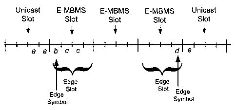
[0029] FIG. 4A illustrates a TDM communication between the base station 110
and
mobile terminals 120 with time slots allocated to unicast and E-MBMS
transmissions in
accordance with one exemplary embodiment. In this particular example, the
first and
fifth time slots are occupied by a unicast transmission and the second, third,
and fourth
time slots are occupied by an E-MBMS transmission. In accordance with the
exemplary
embodiment, the E-MBMS transmission slots include four OFDM symbols for
broadcast transmission and the unicast transmission slots include four OFDM
symbols
for unicast transmission. As previously mentioned, however, the particular
communication protocol utilized for the unicast or E-MBMS transmission need
not
necessarily be limited to OFDM, but may include various other forms of
communication protocols.
[0030] Referring to the example of FIG. 4A, if the first symbol of the E-MBMS
transmission slot is considered a symbol of interest (e.g., symbol "b") for
purposes of
channel estimation, it is desirable to also consider the two symbols preceding
(designated by symbols "a") and the two symbols following (designated by
symbols
"c") the symbol of interest "b" for a more accurate channel estimation.
Because the
symbols "c" (following the symbol "b") are also symbols of a
broadcast.transmission,
the number of pilot tones within symbols "c" provide for a meaningful
comparison with
the number of pilot tones present in symbol "b" for purposes of channel
estimation.
However, because the two preceding symbols "a" are from a unicast
transmission, the
number of pilot tones are proportionally much smaller than the number of pilot
tones
present in the symbols of the broadcast transmission (i.e., symbols "b" and
"c"). As
mentioned, this results because the number of pilot tones used for a broadcast
communication is much greater than the number of pilot tones used for a
unicast
transmission. Accordingly, because of the large disparity between the number
of pilot
tones for a broadcast symbol and a unicast symbol exists, channel estimation
may be
significantly degraded when a symbol from an E-MBMS transmission slot is
adjacent to
a symbol from a unicast transmission slot.
[0031] A solution to this problem may be to increase the number of pilots
within the
symbols. For example; if the number of pilot tones (Np;lot) is 128 and the
number of
data tones (Ndata) is 896 for a total number (Ntotal) of data and pilot tones
of 1,024 for a
CA 02580963 2007-03-20
WO 2006/036759 PCT/US2005/034048
9
particular symbol, then the number of pilot tones Np;lot could be increased to
256;
however, at the expense of decreasing the number of data tones (Ndata) to 768
to achieve
the total number of data and pilot tones (Ntotal) of 1,024 for the symbol.
Accordingly,
when the number of pilot tones (Np;iot) are increased, the number of data
tones (Ndata)
within the symbol are undesirably decreased, thereby causing a decrease in the
overall
data transmission rate between the base station 110 and the mobile terminal
120.
[0032] In accordance with one embodiment, the pilot power and/or the number of
FDM
pilot sub-carriers (or tones) is increased for only an edge symbol of an E-
MBMS edge
slot for purposes of channel estimation using the edge symbol. Referring to
FIG. 4B,
the second time slot of the E-MBMS transmission is considered an "edge" slot
because
it is adjacent to the first time slot of a unicast transmission. The E-MBMS
symbol "b"
is considered an edge symbol because the preceding symbol is a unicast symbol
"a"
from the unicast transmission in the first slot. Similarly, E-MBMS symbol "d"
within
the fourth slot of the E-MBMS transmission is considered an edge symbol
because
symbol "e" is a unicast symbol within the fifth slot of the unicast
transmission that is
adjacent to the E-MBMS symbol "d." The pilot power and/or number of pilot sub-
carriers or tones is increased for channel estimation using edge symbols of
the edge
slots thereby permitting a more accurate channel estimation and, at the same
time,
conserving the data rate for transmission as much as possible. In one
embodiment, the
amount of increase in the pilot power and/or the number of pilot tones may be
configurable within the wireless communication system 100 and/or set by a pre-
defined
amount. It will further be appreciated that the amount of increase in the
pilot power
and/or pilot tones may be stored at the mobile terminal 120 within memory 352,
for
example, and this information may be transmitted to the mobile terminal 120
from the
base station 110.
[0033] Referring to FIG. 5, a process 500 for increasing the pilot power
and/or the
number of pilot sub-carriers or tones for channel estimation is shown in
accordance with
one exemplary embodiment. At block 510, it is determined whether a broadcast
(E-
MBMS) transmission in a given time slot is adjacent to a time slot having a
unicast
transmission (i.e., it is determined whether the E-MBMS transmission occurs
within an
edge slot). At block 520, it is then determined which E-MBMS symbol of the
edge slot
is adjacent to the unicast symbol of a unicast transmission. It will be
appreciated that
CA 02580963 2007-03-20
WO 2006/036759 PCT/US2005/034048
the determination of such edge slots and edge symbols may be carried out in
accordance
with methods that are well-established to those of ordinary skill in the art.
[0034] At block 530, the pilot power and/or the number of pilot sub-carriers
or tones
for the edge symbol (determined in block 520) are increased. In one
embodiment, the
amount of increase in the pilot power and/or the number of pilot tones may be
configurable within the wireless communication system 100 and/or set by a pre-
defined
amount. It will further be appreciated that the amount of increase in the
pilot power
and/or pilot tones may be stored at the mobile terminal 120 within memory 352,
for
example.
[0035] At block 540, channel estimation is then performed on the edge symbol
using
the increased pilot power and/or increased number of pilot sub-carriers or
tones of the
edge symbol. It will be appreciated that the channel estimation may be
performed in
accordance with methods well-established to those of ordinary skill in the
art.
[0036] Those of skill in the art would understand that information and signals
may be
represented using any of a variety of different technologies and techniques.
For
example, data, instructions, commands, information, signals, bits, symbols,
and chips
that may be referenced throughout the above description may be represented by
voltages, currents, electromagnetic waves, magnetic fields or particles,
optical fields or
particles, or any combination thereof.
[0037] Those of skill would further appreciate that the various illustrative
logical
blocks, modules, circuits, and algorithm steps described in connection with
the
embodiments disclosed herein may be implemented as electronic hardware,
computer
software, or combinations of both. To clearly illustrate this
interchangeability of
hardware and software, various illustrative components, blocks, modules,
circuits, and
steps have been described above generally in terms of their functionality.
Whether such
functionality is implemented as hardware or software depends upon the
particular
application and design constraints imposed on the overall system. Skilled
artisans may
implement the described functionality in varying ways for each particular
application,
but such implementation decisions should not be interpreted as causing a
departure from
the scope of the present invention.
[0038] The various illustrative logical blocks, modules, and circuits
described in
connection with the embodiments disclosed herein may be implemented or
performed
with a general purpose processor, a digital signal processor (DSP), an
application
CA 02580963 2007-03-20
WO 2006/036759 PCT/US2005/034048
11
specific integrated circuit (ASIC), a field programmable gate array (FPGA) or
other
programmable logic device, discrete gate or transistor logic, discrete
hardware
components, or any combination thereof designed to perform the functions
described
herein. A general purpose processor may be a microprocessor, but in the
alternative, the
processor may be any conventional processor, controller, microcontroller, or
state
machine. A processor may also be implemented as a combination of computing
devices, e.g., a combination of a DSP and a microprocessor, a plurality of
microprocessors, one or more microprocessors in conjunction with a DSP core,
or any
other such configuration.
[0039] The steps of a method or algorithm described in connection with the
embodiments disclosed herein may be embodied directly in hardware, in a
software
module executed by a processor, or in a combination of the two. A software
module
may reside in RAM memory, flash memory, ROM memory, EPROM memory,
EEPROM memory, registers, hard disk, a removable disk, a CD-ROM, or any other
form of storage medium known in the art. An exemplary storage medium is
coupled to
the processor such the processor can read information from, and write
information to,
the storage medium. In the alternative, the storage medium may be integral to
the
processor. The processor and the storage medium may reside in an ASIC. The
ASIC
may reside in a user terminal. In the alternative, the processor and the
storage medium
may reside as discrete components in a user terminal.
[0040] The previous description of the disclosed embodiments is provided to
enable any
person skilled in the art to make or use the present invention. Various
modifications to
these embodiments will be readily apparent to those skilled in the art, and
the generic
principles defined herein may be applied to other embodiments without
departing from
the spirit or scope of the invention. Thus, the present invention is not
intended to be
limited to the embodiments shown herein but is to be accorded the widest scope
consistent with the principles and novel features disclosed herein.