Sélection de la langue

Search

Sommaire du brevet 2583016 

Énoncé de désistement de responsabilité concernant l'information provenant de tiers

Une partie des informations de ce site Web a été fournie par des sources externes. Le gouvernement du Canada n'assume aucune responsabilité concernant la précision, l'actualité ou la fiabilité des informations fournies par les sources externes. Les utilisateurs qui désirent employer cette information devraient consulter directement la source des informations. Le contenu fourni par les sources externes n'est pas assujetti aux exigences sur les langues officielles, la protection des renseignements personnels et l'accessibilité.

Disponibilité de l'Abrégé et des Revendications

L'apparition de différences dans le texte et l'image des Revendications et de l'Abrégé dépend du moment auquel le document est publié. Les textes des Revendications et de l'Abrégé sont affichés :

  • lorsque la demande peut être examinée par le public;
  • lorsque le brevet est émis (délivrance).
(12) Brevet: (11) CA 2583016
(54) Titre français: SYSTEME D'INJECTION DE MOUSSE
(54) Titre anglais: FOAM DELIVERY SYSTEM
Statut: Accordé et délivré
Données bibliographiques
(51) Classification internationale des brevets (CIB):
  • E02D 03/12 (2006.01)
  • E02D 05/56 (2006.01)
  • E02D 05/62 (2006.01)
  • E02D 07/22 (2006.01)
(72) Inventeurs :
  • MOROSCHAN, CASEY (Canada)
(73) Titulaires :
  • POLY-MOR CANADA INC.
(71) Demandeurs :
  • POLY-MOR CANADA INC. (Canada)
(74) Agent: LAMBERT INTELLECTUAL PROPERTY LAW
(74) Co-agent:
(45) Délivré: 2014-11-25
(22) Date de dépôt: 2007-03-13
(41) Mise à la disponibilité du public: 2008-09-13
Requête d'examen: 2012-02-02
Licence disponible: S.O.
Cédé au domaine public: S.O.
(25) Langue des documents déposés: Anglais

Traité de coopération en matière de brevets (PCT): Non

(30) Données de priorité de la demande: S.O.

Abrégés

Abrégé français

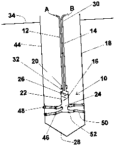
Un système dinjection de mousse comprend deux tubes dinjection qui procurent une chambre de mélange avec une mousse polymère en deux parties. La chambre de mélange mélange la mousse polymère en deux parties sous la surface du sol. Un distributeur avec des bras de distribution décharge la résine polymère en deux parties à partir du système dinjection de mousse. Une méthode de distribution de systèmes dinjection de mousse comprend labaissement du système dinjection de mousse sous la surface du sol et le déchargement dune résine polymère dans la surface du sol à partir dune chambre de mélange située sous la surface du sol. La chambre de mélange décharge la résine polymère pendant que la chambre de mélange est soulevée vers la surface du sol, procurant une base expansible de résine polymère. En raison du fait que les produits chimiques sont mélangés en profondeur, cest-à-dire, à la profondeur des points dinjection souhaités, la possibilité dune prise prématurée et dune obturation du système dinjection est exclue. Un injecteur, comprenant la chambre de mélange et le distributeur, mélange le système de produits chimiques en deux parties à une profondeur et distribue ensuite simultanément les produits chimiques mélangés jusquà six points dinjection à toute profondeur recherchée.


Abrégé anglais

A foam delivery system comprises two delivery tubes providing a mixing chamber with a two-part polymeric foam. The mixing chamber mixes the two-part polymeric foam below a ground surface. A delivery manifold with delivery arms discharges the two-part polymer resin from the foam delivery system. A method of distributing a foam delivery systems comprises lowering a foam delivery system below a ground surface and discharging a polymer resin into the ground surface from a mixing chamber located below the ground surface. The mixing chamber discharges the polymer resin while the mixing chamber is lifted towards the ground surface, providing an expanding base of polymer resin. In that the chemicals are mixed at depth, that is, at the depth of the desired injection points, the possibility of premature setting and plugging of the delivery system is negated. An injector, comprising the mixing chamber and the delivery manifold, mixes the two-part chemical system at depth and then simultaneously distributes the mixed chemicals to up to six injection points at any desired depth.

Revendications

Note : Les revendications sont présentées dans la langue officielle dans laquelle elles ont été soumises.


THE EMBODIMENTS OF THE INVENTION IN WHICH AN EXCLUSIVE PROPERTY OR
PRIVILEGE IS CLAIMED ARE DEFINED AS FOLLOWS:
1. A method of delivering an expanding polymer resin having a first
component and a second
component comprising the steps of:
placing an injector at a first sub-surface location, the injector comprising a
mixing
chamber;
mixing the first component and the second component of the expanding polymer
resin in
the mixing chamber to create a mixed polymer resin;
discharging the mixed polymer resin from the injector at the first sub-surface
location
creating a first foam discharge;
moving the injector to a different sub-surface location;
mixing the first component and the second component of the expanding polymer
resin in
the mixing chamber when the injector is at the different sub-surface location
to create the mixed
polymer resin; and
discharging the mixed polymer resin from the injector at the different sub-
surface location
creating a second foam discharge, the second foam discharge expanding into
contact with the first
foam discharge;
in which the injector discharges the mixed polymer resin continuously as the
injector is
moved to the different subsurface location.
2 The method of delivering an expanding polymer resin of claim 1 in which
the different
sub-surface location is vertically higher than the first sub-surface location.
3 The method of delivering an expanding polymer resin of claim 1 or 2
further comprising
the steps of drilling a borehole into the ground before the step of placing
the injector attached to a
mixing chamber at a sub-surface location and in which the first subsurface
location and the
different sub-surface location lie within the borehole.
4. The method of delivering an expanding polymer resin of any one of claims
1 to 3 in which
the expanding polymer resin is polyurethane.
7

5. A method of delivering a polymer resin below ground surface comprising
the steps of:
creating a bore below the ground surface, the bore being accessible from the
ground
surface;
lowering a mixing chamber into the bore, the mixing chamber being a component
of a foam
delivery system;
discharging a polymer resin from the mixing chamber of the foam delivery
system into the
bore;
lifting the mixing chamber within the bore; and
further discharging polymer resin from the mixing chamber of the foam delivery
system
after lifting the mixing chamber within the bore;
in which the polymer resin is discharged continuously from the foam delivery
system as
the foam delivery system is lifted within the bore.
6. A method of delivering a polymer resin below ground surface comprising
the steps of:
creating a bore below the ground surface, the bore being accessible from the
ground
surface;
lowering a mixing chamber into the bore, the mixing chamber being a component
of a foam
delivery system;
discharging a polymer resin from the mixing chamber of the foam delivery
system into the
bore;
lifting the mixing chamber within the bore; and
further discharging polymer resin from the mixing chamber of the foam delivery
system
after lifting the mixing chamber within the bore;
in which the step of creating a bore below surface and being accessible from
the ground
surface is performed by the foam delivery system.
7. A method of delivering a polymer resin below ground surface comprising
the steps of:
creating a bore below the ground surface, the bore being accessible from the
ground
surface;
8

lowering a mixing chamber into the bore, the mixing chamber being a component
of a foam
delivery system;
discharging a polymer resin from the mixing chamber of the foam delivery
system into the
bore;
lifting the mixing chamber within the bore; and
further discharging polymer resin from the mixing chamber of the foam delivery
system
after lifting the mixing chamber within the bore;
in which the polymer resin is discharged continuously from the foam delivery
system as
the foam delivery system is lifted within the bore; and
in which the step of creating a bore below surface and being accessible from
the ground
surface is performed by the foam delivery system.
8. A method of delivering a polymer resin below ground surface comprising
the steps of:
creating a bore below the ground surface, the bore being accessible from the
ground
surface;
lowering a mixing chamber into the bore, the mixing chamber being a component
of a foam
delivery system;
discharging a polymer resin from the mixing chamber of the foam delivery
system into the
bore;
lifting the mixing chamber within the bore; and
further discharging polymer resin from the mixing chamber of the foam delivery
system
after lifting the mixing chamber within the bore;
in which the polymer resin is discharged in discrete steps from the foam
delivery system
as the foam delivery system is lifted within the bore; and
in which the step of creating a bore below surface and being accessible from
the ground
surface is performed by the foam delivery system.
9. A method of delivering a polymer resin below ground surface comprising
the steps of:
creating a bore below the ground surface, the bore being accessible from the
ground
surface;
9

lowering a mixing chamber into the bore, the mixing chamber being a component
of a foam
delivery system;
discharging a polymer resin from the mixing chamber of the foam delivery
system into the
bore;
lifting the mixing chamber within the bore;
further discharging polymer resin from the mixing chamber of the foam delivery
system
after lifting the mixing chamber within the bore; and
releasing excess air from the foam delivery system prior to the step of
discharging a
polymer resin from the foam delivery system.
10. A method of delivering a polymer resin below ground surface comprising
the steps of:
creating a bore below the ground surface, the bore being accessible from the
ground
surface;
lowering a mixing chamber into the bore, the mixing chamber being a component
of a foam
delivery system;
discharging a polymer resin from the mixing chamber of the foam delivery
system into the
bore;
lifting the mixing chamber within the bore;
further discharging polymer resin from the mixing chamber of the foam delivery
system
after lifting the mixing chamber within the bore; and
releasing excess air from the foam delivery system prior to the step of
discharging a
polymer resin from the foam delivery system;
in which the polymer resin is discharged continuously from the foam delivery
system as
the foam delivery system is lifted within the bore.
11. A method of delivering a polymer resin below ground surface comprising
the steps of:
creating a bore below the ground surface, the bore being accessible from the
ground
surface;
lowering a mixing chamber into the bore, the mixing chamber being a component
of a foam
delivery system;

discharging a polymer resin from the mixing chamber of the foam delivery
system into the
bore;
lifting the mixing chamber within the bore;
further discharging polymer resin from the mixing chamber of the foam delivery
system
after lifting the mixing chamber within the bore; and
releasing excess air from the foam delivery system prior to the step of
discharging a
polymer resin from the foam delivery system;
in which the polymer resin is discharged in discrete steps from the foam
delivery system
as the foam delivery system is lifted within the bore.
12. A method of delivering a polymer resin below ground surface comprising
the steps of:
creating a bore below the ground surface, the bore being accessible from the
ground
surface;
lowering a mixing chamber into the bore, the mixing chamber being a component
of a foam
delivery system;
discharging a polymer resin from the mixing chamber of the foam delivery
system into the
bore;
lifting the mixing chamber within the bore;
further discharging polymer resin from the mixing chamber of the foam delivery
system
after lifting the mixing chamber within the bore; and
releasing excess air from the foam delivery system prior to the step of
discharging a
polymer resin from the foam delivery system;
in which the step of creating a bore below surface and being accessible from
the ground
surface is performed by the foam delivery system.
13. A method of delivering a polymer resin below ground surface comprising
the steps of:
creating a bore below the ground surface, the bore being accessible from the
ground
surface;
lowering a mixing chamber into the bore, the mixing chamber being a component
of a foam
delivery system;
11

discharging a polymer resin from the mixing chamber of the foam delivery
system into the
bore;
lifting the mixing chamber within the bore;
further discharging polymer resin from the mixing chamber of the foam delivery
system
after lifting the mixing chamber within the bore; and
releasing excess air from the foam delivery system prior to the step of
discharging a
polymer resin from the foam delivery system;
in which the polymer resin is discharged continuously from the foam delivery
system as
the foam delivery system is lifted within the bore; and
in which the step of creating a bore below surface and being accessible from
the ground
surface is performed by the foam delivery system.
14. A method of delivering a polymer resin below ground surface comprising
the steps of:
creating a bore below the ground surface, the bore being accessible from the
ground
surface;
lowering a mixing chamber into the bore, the mixing chamber being a component
of a foam
delivery system;
discharging a polymer resin from the mixing chamber of the foam delivery
system into the
bore;
lifting the mixing chamber within the bore;
further discharging polymer resin from the mixing chamber of the foam delivery
system
after lifting the mixing chamber within the bore; and
releasing excess air from the foam delivery system prior to the step of
discharging a
polymer resin from the foam delivery system;
in which the polymer resin is discharged in discrete steps from the foam
delivery system
as the foam delivery system is lifted within the bore; and
in which the step of creating a bore below surface and being accessible from
the ground
surface is performed by the foam delivery system.
12

Description

Note : Les descriptions sont présentées dans la langue officielle dans laquelle elles ont été soumises.


CA 02583016 2007-03-13
FOAM DELIVERY SYSTEM
BACKGROUND
[0001] This patent document relates to a system to deliver two-part expanding
polymeric
resins to below surface depths.
[0002] In a typical two-part expanding polymeric resin system, the two
chemical
components are impingement-mixed at the surface through appropriate
pumping/proportioner
equipment and delivered through a single injection tube or probe. The depth to
which the
mixed components can be delivered is limited to: (a) the time it takes the
mixed components
to gel and "set-up" which is a function of the density/mix of the resin system
and the
temperature the resin is injected; (b) the back-pressure created at the end of
the probe due to
the expansion of the resin after it is injected; (c) if air-locks within the
delivery probe occur;
and (d) the pressures the mixed material can be injected through a single
probe.
[0003] The gel time of typical two-part expanding resin systems is generally
very short
and usually measured in seconds. The more reactive or faster is the expansion
of the resin
system, the quicker the gel time or set-up time. Similarly, within limits, as
the temperature of
the chemicals increase, the gel time or set-up time decreases. The gel time or
set-up time often
limits the depths to which an already-mixed polymeric resin system can be
delivered before
the material "sets up" and plugs the injection probe.
[0004] Once the mixed expanding resin is injected through the injection probe,
a back-
pressure often develops around the base of the area of the injection and the
back-pressure
slows down the rate of injection of the mixed resin, which causes the resin to
prematurely set-
up in the injection probe and plugs the probe.
[0005] If the soils at depth into which the expanding resin system is being
injected into are
very cohesive or saturated, the air within the injection probe could create an
air-lock as the
chemicals are being delivered from the surface through a single injection
probe. At the very
least, the back pressure caused by the air within the injection probe will
slow the progress of
the mixed two-part resin system and therefore minimize the amount of material
that can be
injected before the expanding resin system sets-up and plugs the probe
[0006] There is a direct relationship between the pressure at which the mixed
resins are
1

CA 02583016 2007-03-13
injected and the depth to which the resins can be delivered. The higher the
pressure the faster
the material can be delivered through a single injection probe and therefore
the deeper and the
longer the material can be delivered before the resin sets-up and plugs the
injection probe.
Despite applied pressures in delivering the two-part resin through a single
probe, eventually
the probe will plug due to depth and/or back-pressure.
SUMMARY
[0007] This patent document addresses these and other difficulties with the
prior art.
[0008] In an embodiment there is a method of delivering a polymer resin below
ground
surface. A bore that is accessible from the ground surface is created below
the ground surface.
A mixing chamber, which is a component of a foam delivery system, is lowered
into the bore.
A polymer resin is discharged from the mixing chamber of the foam delivery
system into the
bore. The mixing chamber is lifted within the bore and the polymer resin is
discharged from
the foam delivery system when the foam delivery system is lifted within the
bore.
[0009] In an embodiment there is a foam delivery system for delivering an
expanding
polymer resin below a ground surface. The foam delivery system has a first
delivery tube
having a surface end and a mixing end and a second delivery tube having a
surface end and a
mixing end. A mixing chamber is attached to the respective mixing ends of each
of the first
and second delivery tubes. A first delivery arm and a second delivery arm
provide a pathway
from and connect to the mixing chamber for discharging the expanding polymeric
resin from
the mixing chamber.
[0010] In an embodiment there is a method of delivering an expanding polymer
resin
having a first component and a second component. An injector, which comprises
a mixing
chamber, is placed at a first sub-surface location. The first component and
the second
component of the expanding polymer resin are mixed in the mixing chamber to
create a mixed
polymer resin. The mixed polymer resin is discharged from the injector at the
first sub-surface
location creating a first foam discharge. The injector is moved to a different
sub-surface
location. The first component and the second component of the expanding
polymer resin are
mixed in the mixing chamber when the injector is at the different sub-surface
location to
create the mixed polymer resin. The mixed polymer resin is discharged from the
injector at
2

CA 02583016 2007-03-13
the different sub-surface location creating a second foam discharge, which
expands into
contact with the first foam discharge.
[0011] These and other aspects of the device and method are set out in the
claims, which
are incorporated here by reference.
BRIEF DESCRIPTION OF THE FIGURES
[00121 Embodiments will now be described with reference to the figures, in
which like
reference characters denote like elements, by way of example, and in which:
Fig. 1 is a partial section view of a foam delivery system in a screw pile;
Fig. 2 is a partial section view of a foam delivery system in a first sub-
surface
location in a bore; and
Fig. 3 is a partial section view of a foam delivery system in a second sub-
surface
location in a bore.
DETAILED DESCRIPTION
[00131 In the claims, the word "comprising" is used in its inclusive sense and
does not
exclude other elements being present. The indefinite article "a" before a
claim feature does
not exclude more than one of the feature being present. Each one of the
individual features
described here may be used in one or more embodiments and is not, by virtue
only of being
described here, to be construed as essential to all embodiments as defined by
the claims.
[0014] Figs. 1- 3 show embodiments of a foam delivery system 10. The foam
delivery
system 10 has a first delivery tube 12 and a second delivery tube 14 each
having a surface end
30 and a mixing end 32. An injector 16 comprising a mixing chamber 22 is
attached to the
respective mixing ends 32 of each of the first and second delivery tubes 12,
14. A delivery
manifold 24 comprising first and second delivery arms 52 connects to the
mixing chamber 22
and provides a pathway for discharging the expanding polymeric resin from the
mixing
chamber 22. Air bleed valves 20 connect to the mixing ends 32 of the first and
second
delivery tubes 12, 14. The air bleed valves 20 are hard fixed into each of the
first and second
delivery tubes 12, 14 thereby preventing the possibility of air locks as the
two components
Component "A" and Component "B" are pumped through the delivery tubes 12, 14
to depth.
3

CA 02583016 2007-03-13
[0015] Figs. 2 and 3 show an embodiment of the foam delivery system 10 in
operation.
The foam delivery system 10 delivers an expanding polymer resin having a first
component
(Component "A") and a second component (Component "B") into a sub-surface
location
through the first and second delivery tubes 12 and 14, respectively. The
injector 16 is placed
at a first sub-surface location, for example the position shown in Fig. 2. The
first component
and the second component of an expanding polymer resin are transported through
the first and
second delivery tubes 12, 14 to the mixing chamber 22 to create a mixed
polymer resin 38.
The mixed polymer resin 38 is discharged from the injector 16 at the first sub-
surface location
to create a first foam discharge 40. The injector 16 is moved to a different
sub-surface
location as shown in Fig. 3. Again, the first and second components of the
expanding polymer
resin are mixed in the mixing chamber 22 when the injector 16 is at the
different sub-surface
location to create the mixed polymer resin. The mixed polymer resin is
discharged from the
injector 16 at the different sub-surface location creating a second foam
discharge 42 so that
the second foam discharge 42 expands into contact with the first foam
discharge 40 as shown
in Fig. 3.
[0016] To deliver foam below a ground surface 34 a bore 36 (Fig. 2) may be
created below
the ground surface 34 prior to operation of the foam delivery system 10. In
the embodiment of
Fig. 1, the foam delivery system 101ies within a screw pile having a drill
stem wall 18 and a
screw 28 at the base to bore into the ground. As shown in Fig. 2, the bore 36
is accessible
from the ground surface 34. In the embodiment of Fig. 2 the mixing chamber 22
is lowered
into the bore 36. A polymer resin is discharged from the mixing chamber 22 of
the foam
delivery system 10 into the bore 36. The foam mixing chamber 22 is lifted
within the bore 36.
The polymer resin is discharged from the foam delivery system 10 when the foam
delivery
system 10 is lifted within the bore 36. For example, the foam delivery system
10 may
continuously discharge the polymer resin as the foam delivery system 10 is
lifted in the bore
36.
[0017] Fig. 1 shows an embodiment in which the pile stem 44 containing the
foam
delivery system 10 is a drill stem that can be driven, screwed or drilled to
the desired depth.
Component "A" and Component "B" are independently pumped in the desired
proportions
through delivery tubes 12, 14 to the depth that the mixed polymer resin is to
be injected. The
4

CA 02583016 2007-03-13
polymer resin is injected to the exterior of the drill stem wall 18. Below the
air bleed valves
20 are a mixing chamber 22 and delivery manifold 24 which together comprise
the injector
16, or mixing /manifold delivery module. The delivery arms 52 of the delivery
manifold 24
attach to a connecting tube 50 that attaches between a port 46 of the delivery
arm 52 and a
stem wall port 48 in the drill stem wall 18. The stem wall ports 48 in the
drill stem wall 18
may be pre-attached to the connecting tubes 50 prior to being lowered into the
ground. The air
bleed valves 20 are each appropriately-sized conventional air bleed valves and
are affixed to
each of the delivery tubes 12, 14 to evacuate air from the delivery tubes 12,
14 as the two
liquids, Components "A" and "B", are being pumped into the delivery tubes 12,
14.
[0018) Below the mixing end 32 of the delivery tubes 12, 14, the two
Components "A"
and "B" combine together in the mixing chamber 22. The mixing chamber 22
comprises off-
setting arms 26, which may be appropriately angled and spiraled to effect
maximum mixing
of the two chemicals coupled with opposing flow of the chemicals themselves.
[0019] In other embodiments, the pile stem may be a different form of hollow
pipe. For
example, the pile stem may be a drill stem or a conduit
(0020] In other embodiment other expandable synthetic substances having
similar
properties may be used. The particular resin system used can be tailored to
meet specific
design applications relating to compressive strength, tensile strength, shear
strength, flexural
strength and other structural characteristics to meet the specific design
application of the resin
system for any given project. In some embodiments, for example, the polymeric
resin system
to be delivered at depth may be a high density, two-part, closed-cell, hydro-
insensitive
polymer resin, such as a polyurethane system.
[0021] In some embodiments, the delivery tubes or probes can be made of metal
such as
aluminum, copper, steel or other metal or, made of a synthetic material such
as rigid or
flexible plastics, fiberglass or other synthetic material. The delivery tubes
12, 14 could be
sectional with each section being welded, friction fitted, glued, screwed or
joined together in
some other fashion. The embodiments of Figs. 1 to 3 show schematic designs of
the foam
delivery system 10. In other embodiments, various orientations and shapes of
the components
of the foam delivery system are possible.
[0022] In some embodiments, the delivery tubes 12 and 14 can be, for example
made of

CA 02583016 2007-03-13
rigid metal, synthetic material or flexible metal through which each of the
two component
parts of the expanding resin will be individually pumped to the desired depth.
The delivery
tubes 12 and 14, which for example, may have a'/4" - 3/4" inside diameter or
larger, may be
constructed from one continuous length or may be sectional and glued, welded,
screwed,
friction fit, or otherwise fit together to form a delivery tube of the desired
length. The
pumping system(s) may be, for example, a conventional pumping and/or
proportioner
equipment readily available in the marketplace capable of pumping the two
components in
their proper proportions into the delivery system described in this Patent
document.
[0023] The foam delivery system 10 may be used in a variety of applications,
for example
for stabilizing and/or densifying base soils at extreme depths, for
stabilizing around the base
of screw-piles and other types of piles that have been screwed or placed at
depth, for
densifying base soils in earth quake prone zones as a prevention against
liquefaction, for
filling voids along vertical planes at depth in such cases as for example old
mine tunnels and
shafts, new mining tunnels and shafts, conduits, or any other structure
resting along a vertical
plane that requires back-filling and stabilization and for filling voids along
horizontal planes
in such cases as for example abandoned conduit, culverts, mined tunnels, or
any other
structure resting along a horizontal plane that requires void-filling.
[0024] Immaterial modifications may be made to the embodiments described here
without
departing from what is covered by the claims.
6

Dessin représentatif
Une figure unique qui représente un dessin illustrant l'invention.
États administratifs

2024-08-01 : Dans le cadre de la transition vers les Brevets de nouvelle génération (BNG), la base de données sur les brevets canadiens (BDBC) contient désormais un Historique d'événement plus détaillé, qui reproduit le Journal des événements de notre nouvelle solution interne.

Veuillez noter que les événements débutant par « Inactive : » se réfèrent à des événements qui ne sont plus utilisés dans notre nouvelle solution interne.

Pour une meilleure compréhension de l'état de la demande ou brevet qui figure sur cette page, la rubrique Mise en garde , et les descriptions de Brevet , Historique d'événement , Taxes périodiques et Historique des paiements devraient être consultées.

Historique d'événement

Description Date
Inactive : Certificat d'inscription (Transfert) 2022-10-14
Inactive : Transferts multiples 2022-08-24
Exigences relatives à la révocation de la nomination d'un agent - jugée conforme 2020-04-22
Exigences relatives à la nomination d'un agent - jugée conforme 2020-04-22
Représentant commun nommé 2019-10-30
Accordé par délivrance 2014-11-25
Inactive : Page couverture publiée 2014-11-24
Préoctroi 2014-08-11
Inactive : Taxe finale reçue 2014-08-11
Un avis d'acceptation est envoyé 2014-03-12
Lettre envoyée 2014-03-12
Un avis d'acceptation est envoyé 2014-03-12
Inactive : Q2 réussi 2014-03-10
Inactive : Approuvée aux fins d'acceptation (AFA) 2014-03-10
Modification reçue - modification volontaire 2014-02-11
Inactive : Dem. de l'examinateur par.30(2) Règles 2013-08-20
Modification reçue - modification volontaire 2013-07-03
Inactive : Dem. de l'examinateur par.30(2) Règles 2013-03-27
Lettre envoyée 2012-02-15
Exigences pour une requête d'examen - jugée conforme 2012-02-02
Toutes les exigences pour l'examen - jugée conforme 2012-02-02
Requête d'examen reçue 2012-02-02
Lettre envoyée 2009-09-02
Inactive : Lettre officielle 2009-07-21
Requête visant une déclaration du statut de petite entité reçue 2009-02-20
Déclaration du statut de petite entité jugée conforme 2009-02-20
Requête visant une déclaration du statut de petite entité reçue 2009-02-20
Demande publiée (accessible au public) 2008-09-13
Inactive : Page couverture publiée 2008-09-12
Inactive : CIB attribuée 2007-09-19
Inactive : CIB en 1re position 2007-09-19
Inactive : CIB attribuée 2007-09-19
Inactive : Certificat de dépôt - Sans RE (Anglais) 2007-04-26
Demande reçue - nationale ordinaire 2007-04-26

Historique d'abandonnement

Il n'y a pas d'historique d'abandonnement

Taxes périodiques

Le dernier paiement a été reçu le 2013-12-20

Avis : Si le paiement en totalité n'a pas été reçu au plus tard à la date indiquée, une taxe supplémentaire peut être imposée, soit une des taxes suivantes :

  • taxe de rétablissement ;
  • taxe pour paiement en souffrance ; ou
  • taxe additionnelle pour le renversement d'une péremption réputée.

Les taxes sur les brevets sont ajustées au 1er janvier de chaque année. Les montants ci-dessus sont les montants actuels s'ils sont reçus au plus tard le 31 décembre de l'année en cours.
Veuillez vous référer à la page web des taxes sur les brevets de l'OPIC pour voir tous les montants actuels des taxes.

Historique des taxes

Type de taxes Anniversaire Échéance Date payée
Taxe pour le dépôt - générale 2007-03-13
TM (demande, 2e anniv.) - petite 02 2009-03-13 2009-02-20
TM (demande, 3e anniv.) - petite 03 2010-03-15 2010-03-08
TM (demande, 4e anniv.) - petite 04 2011-03-14 2011-03-07
TM (demande, 5e anniv.) - petite 05 2012-03-13 2012-02-02
Requête d'examen - petite 2012-02-02
TM (demande, 6e anniv.) - petite 06 2013-03-13 2013-01-04
TM (demande, 7e anniv.) - petite 07 2014-03-13 2013-12-20
Taxe finale - petite 2014-08-11
TM (brevet, 8e anniv.) - petite 2015-03-13 2015-02-27
TM (brevet, 9e anniv.) - petite 2016-03-14 2016-02-04
TM (brevet, 10e anniv.) - petite 2017-03-13 2017-01-06
TM (brevet, 11e anniv.) - petite 2018-03-13 2017-12-01
TM (brevet, 12e anniv.) - petite 2019-03-13 2018-10-04
TM (brevet, 13e anniv.) - petite 2020-03-13 2019-11-21
TM (brevet, 14e anniv.) - petite 2021-03-15 2020-12-22
TM (brevet, 15e anniv.) - petite 2022-03-14 2022-01-20
Enregistrement d'un document 2022-08-24
TM (brevet, 16e anniv.) - petite 2023-03-13 2023-01-17
TM (brevet, 17e anniv.) - petite 2024-03-13 2023-12-18
Titulaires au dossier

Les titulaires actuels et antérieures au dossier sont affichés en ordre alphabétique.

Titulaires actuels au dossier
POLY-MOR CANADA INC.
Titulaires antérieures au dossier
CASEY MOROSCHAN
Les propriétaires antérieurs qui ne figurent pas dans la liste des « Propriétaires au dossier » apparaîtront dans d'autres documents au dossier.
Documents

Pour visionner les fichiers sélectionnés, entrer le code reCAPTCHA :


Pour visualiser une image, cliquer sur un lien dans la colonne description du document. Pour télécharger l'image (les images), cliquer l'une ou plusieurs cases à cocher dans la première colonne et ensuite cliquer sur le bouton "Télécharger sélection en format PDF (archive Zip)" ou le bouton "Télécharger sélection (en un fichier PDF fusionné)".

Liste des documents de brevet publiés et non publiés sur la BDBC .

Si vous avez des difficultés à accéder au contenu, veuillez communiquer avec le Centre de services à la clientèle au 1-866-997-1936, ou envoyer un courriel au Centre de service à la clientèle de l'OPIC.


Description du
Document 
Date
(aaaa-mm-jj) 
Nombre de pages   Taille de l'image (Ko) 
Description 2007-03-12 6 327
Revendications 2007-03-12 3 110
Abrégé 2007-03-12 1 28
Dessins 2007-03-12 2 30
Dessin représentatif 2008-08-20 1 7
Revendications 2013-07-02 2 74
Revendications 2014-02-10 6 215
Certificat de dépôt (anglais) 2007-04-25 1 158
Rappel de taxe de maintien due 2008-11-16 1 115
Rappel - requête d'examen 2011-11-14 1 118
Accusé de réception de la requête d'examen 2012-02-14 1 189
Avis du commissaire - Demande jugée acceptable 2014-03-11 1 161
Paiement de taxe périodique 2023-12-17 1 26
Taxes 2012-02-01 1 155
Taxes 2013-01-03 1 154
Correspondance 2007-04-25 1 60
Correspondance 2008-11-16 1 37
Taxes 2009-02-19 2 50
Correspondance 2009-02-19 2 50
Taxes 2009-02-19 2 50
Correspondance 2009-02-19 2 50
Correspondance 2009-02-19 2 51
Taxes 2009-02-19 2 51
Correspondance 2009-07-20 1 17
Correspondance 2009-09-01 1 15
Taxes 2009-02-19 2 69
Correspondance 2009-07-27 2 42
Taxes 2010-03-07 1 26
Taxes 2011-03-06 1 200
Taxes 2013-12-19 1 23
Correspondance 2014-08-10 1 25
Taxes 2015-02-26 1 24
Taxes 2016-02-03 1 24
Taxes 2017-01-05 1 24
Paiement de taxe périodique 2020-12-21 1 25
Paiement de taxe périodique 2022-01-19 1 25
Paiement de taxe périodique 2023-01-16 1 26