Note : Les descriptions sont présentées dans la langue officielle dans laquelle elles ont été soumises.
CA 02586641 2007-05-04
WO 2006/052894 PCT/US2005/040299
BLOOD CLOT FILTER CONFIGURED FOR A WIRE GUIDE
RELATED APPLICATION
[0001] This application claims the benefit of U.S. Provisional Application No.
60/625,900 filed November 8, 2004, the entire contents of which are
incorporated
herein by reference.
BACKGROUND
[0002] This invention relates to medical devices. More specifically, the
invention relates to a removable vena cava clot filter.
[0003] Filtering devices that are percutaneously placed in the vena cava have
been available for a number of years. A need for filtering devices arises in
trauma
patients, orthopedic surgery patients, neurosurgery patients, or in patients
having
medical conditions requiring bed rest or non-movement because of the
likelihood of
thrombosis in the peripheral vasculature of patients. The thrombi may break
away
from the vessel wall, and, depending on the size of the thrombi, pose a
serious risk
of pulmonary embolism when blood clots migrate from the peripheral vasculature
through the heart and into the lungs.
[0004] A filtering device can be deployed in the vena cava of a patient when,
for example, anticoagulant therapy is contraindicated or has failed.
Typically,
filtering devices are permanent implants even though the condition or medical
problem that required the device has passed. Recently, filters have been
employed
or considered in preoperative patients and in patients predisposed to
thrombosis,
which, however, may increase the risk for pulmonary embolism in these
patients.
1
CA 02586641 2007-05-04
WO 2006/052894 PCT/US2005/040299
[0005] Although the benefits of vena cava filters have been well established,
improvements may be made. For example, filters generally have not been
considered removable from a patient due to the likelihood of endotheliosis of
the
filter or fibrous reaction matter adherent to the endothelium during
treatment. After
deployment of a filter in a patient, proliferating intimal cells begin to
accumulate
around the filter struts that are in contact with the wall of the vessel.
After a period of
time, such ingrowth prevents removal of the filter without risk of trauma,
requiring the
filter to remain in the patient. As a result, there is a need for an effective
filter that
can be removed after the underlying medical condition has passed.
[0006] Although some filters have been designed to be removable from the
vena cava, these filters commonly become off-centered or tilted with respect
to the
hub of the filter and the longitudinal axis of the vessel in which it has been
inserted.
As a result, these filters including the hub and the retrieval hook engage the
vessel
wall along their lengths and potentially become endothelialized within the
vessel,
making removal of the filters impossible or at least difficult.
SUMMARY
[0007] In a general aspect, the present invention provides a filter that
includes
a hub and a plurality of primary struts and a plurality of secondary struts
that extend
from the hub. Each primary strut terminates with a hook to anchor the filter
in the
blood vessel when the filter is deployed in the blood vessel. The secondary
struts
center the filter in the blood vessel as the secondary struts engage the
interior of the
blood vessel during deployment of the filter.
2
CA 02586641 2007-05-04
WO 2006/052894 PCT/US2005/040299
[0008] To guide the filter through a vessel, the hub is provided with a
passageway through which a wire guide is received. Thus, the wire guide can be
extended through a sheath so that the terminal end of the wire guide can be
placed
near the site of interest. A medical specialist, such as a physician, can then
push
the filter along the wire guide to the desired location. Once the filter is
deployed,
both the sheath and wire guide are removed from the patient. The hub may be
provided with a groove that engages with a retrieval device to remove the
filter from
the vessel.
[0009] Each of the primary struts and the secondary struts includes a fixed
end housed in the hub. These fixed ends are secured together in a bundle that
defines a central axis extending through the passageway. The central axis is
substantially parallel to a longitudinal axis extending through the blood
vessel when
the filter centers itself in the blood vessel.
[0010] In various embodiments, the filter has a collapsed configuration and an
expanded configuration. The filter expands from the collapsed configuration to
the
expanded configuration as the filter is deployed in the blood vessel. The
primary
struts and secondary struts form a net when the filter is in the expanded
configuration to capture blood clots.
[0011] The hooks may include barbs that engage the interior wall of the blood
vessel. The primary struts and the secondary struts can be made of shape
memory
alloy.
[0012] In some embodiments, the primary struts are spaced apart angularly
about the passageway such that the spacing between the primary struts are
substantially equal. A pair of secondary struts may be positioned between each
pair
3
CA 02586641 2007-05-04
WO 2006/052894 PCT/US2005/040299
of spaced apart primary struts, or a primary strut may be positioned between a
respective pair of secondary struts.
[0013] In a particular embodiment, the filter includes four primary struts and
eight secondary struts.
[0014] Further features and advantages of this invention will become readily
apparent from the following description, and from the claims.
BRIEF DESCRIPTION OF THE DRAWINGS
[0015] FIG. 1 is an illustration of the anatomy the vena cava in which a
filter is
deployed in accordance with an embodiment of the invention.
[0016] FIG. 2 is a side perspective view of a vena cava filter in accordance
with an embodiment of the invention.
[0017] FIG. 3 is a close-up view of a hub associated with filter shown in FIG.
2.
[0018] FIG. 4a is a cross-sectional view of the hub along the line 4-4 of FIG.
3.
[0019] FIG. 4b is a cross-sectional view of an alternative hub in accordance
with the invention.
[0020] FIG. 5a is a cross-sectional view of a blood vessel showing the
insertion of a wire guide.
[0021] FIG. 5b is a cross-sectional view of the blood vessel showing the
insertion of a sheath and a vena cava filter over the wire guide.
[0022] FIG. 5c is a cross-sectional view of the blood vessel showing the vena
cava filter partially deployed.
4
CA 02586641 2007-05-04
WO 2006/052894 PCT/US2005/040299
[0023] FIG. 6a is a cross-sectional view of the blood vessel showing the
retraction of the sheath.
[0024] FIG. 6b is a cross-sectional view of the blood vessel showing the vena
cava filter fully deployed.
[0025] FIG. 7 is a cross-sectional view of a blood vessel showing the vena
cava filter of FIG. 2 deployed within the blood vessel.
[0026] FIG. 8 is a view of the blood vessel and filter of FIG. 7 taken along
the
line 8-8.
[0027] FIGs. 9a through 9e are interior views of the vena cava illustrating
the
removal of the vena cava filter.
DETAILED DESCRIPTION
[0028] Turning now to the drawings, FIG. 1 illustrates a vena cava filter 20
embodying the principles of the present invention. The vena cava filter 20 is
shown
implanted in a vena cava 22 after it has been inserted through an iliac vein
24 with
the use of a sheath 26. Alternatively, the vena cava filter 20 can be inserted
through
a jugular vein. As described below in greater detail, once implanted, the vena
cava
filter 20 is able to self align itself within the vena cava 22 to minimize
endotheliosis of
the filter. The vena cava filter 20 captures or lyses thrombi (or clots)
carried through
the vena cava 22 from the iliac veins 24, 28 toward the heart and into the
pulmonary
arteries, where clots can cause embolization. Moreover, the vena cava filter
20 is
configured to minimize obstruction of flood flow through the vena cava 22.
[0029] The iliac veins 24, 28 from the legs merge into the vena cava 22 at a
juncture 30, and the renal veins 32 from the kidneys 34 join the vena cava 22
downstream of the juncture 30. The portion of the vena cava between the
juncture
CA 02586641 2007-05-04
WO 2006/052894 PCT/US2005/040299
30 and the renal veins 32 defines an inferior vena cava 36. In the illustrated
embodiment, the length of a vena cava filter 20 is shorter than the length of
the
inferior vena cava 36. Otherwise, if the lower part of the filter 20 extends
into the
iliac veins 24, 28, the filtering effectiveness of the filter 20 may be
compromised.
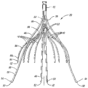
[0030] Referring now to FIGs. 2, 3, and 4, the filter 20 includes four primary
struts 38 and eight secondary struts 40, each of which extends from a
respective
fixed end housed in a hub 42. To attach the fixed ends of the struts to the
hub 42,
the fixed ends are crimped together in a compact bundle about an opening or
passageway 43, thereby defining a central or longitudinal axis 44. The
diameter of
this bundle is minimized to accommodate the size of the wires used to form the
struts. The hub 42 is provided with a groove 45, which, as described below,
engages with a retrieval device for removing the vena cava filter 20.
[0031] Each primary strut 38 is formed with a first curved section 46 that
bends away form the central axis 44 and a second curved section 48 that bends
away from the hub 42. A substantially straight section 50 extends from the
second
curved section 48 and terminates in an anchoring hook 52 with a barb 54. The
section 50 may also have an additional curved section 55 that further flares
the
anchoring hooks 52 away from the central axis 44. Each primary strut 38
maintains
a non-parallel relationship with the central axis 44 when the filter 20 is in
its deployed
configuration.
[0032] When the filter 20 is deployed in the blood vessel (see, for example,
FIG. 7), the anchoring hooks 52 engage with the interior of the blood vessel
in a first
axial plane 57 aligned substantially perpendicular to the longitudinal axis of
the blood
vessel. The diameter of this plane of engagement 57 is about 30 mm or less.
6
CA 02586641 2007-05-04
WO 2006/052894 PCT/US2005/040299
[0033] The primary struts 38 have sufficient spring strength to move the hooks
52 to the interior wall, where the hooks 52, in particular, the barbs 54,
anchor into
the interior wall of the blood vessel to prevent the filter 20 from migrating
from the
delivery location of the filter in the blood vessel. In various embodiments,
the
primary struts 38 are formed from superelastic material, stainless steel wire,
MP35N,
Nitinol, eigiloy, chronichrome, cobalt chrome alloy or any other suitable
material that
will result in a self-opening or self-expanding filter. In certain
embodiments, the
primary struts 38 are formed from wire with a round or near round cross
section with
a diameter of at least about 0.015 inch. In other embodiments, the primary
struts do
not have a round cross-section. For example, the primary struts 38 can take on
any
shape with rounded edges to maintain non-turbulent blood flow. Rather than
forming the struts from wire, they can be cut from a tube of any appropriate
material
by laser cutting, electrical discharge machining, or any other suitable
process.
Subsequently, the struts can be finished, for example, with an
electropolishing
process so that the resulting struts are substantially rounded.
[0034] A pair of secondary struts 40 is positioned between adjacent primary
struts 38 as shown in FIG. 4a, or, alternatively, a primary strut 38 is
positioned
between a pair of secondary struts 40 as shown in FIG. 4b. Each secondary
strut 40
has a first curved section 56 that bends away from the central axis 44, a
second
curved or converging section 58 that bends toward the central axis 44, and an
end
section 60 that terminates in a tip 62 pointing toward the central axis 44.
The tips 62
are located longitudinally between the hub 42 and the anchoring hooks 54 of
the
primary struts 38. To minimize the trauma to the vena cava caused by removing
the
filter 20, the free ends 60 of the secondary struts 40 do not have anchoring
hooks.
7
CA 02586641 2007-05-04
WO 2006/052894 PCT/US2005/040299
[0035] When the filter 20 is in its deployed configuration, the outer regions
58a of the converging section 58 of each secondary strut 40 engage with the
wall of
the blood vessel. The radial force created between the secondary struts 40 and
the
wall of the blood vessel serves to align the filter 20 about the center of the
blood
vessel so that the central axis 44 is substantially parallel to the axis of
the blood
vessel.
[0036] When the filter 20 is deployed within the vessel, the outer regions 58a
of the secondary struts 40 engage with the interior of the blood vessel in a
second
axial plane 65 (FIG. 7) that is substantially parallel to the first axial
plane 57. The
diameter of the second axial plane of engagement is also about 30 mm or less.
As a
result, the filter 20 has two layers or planes of struts longitudinally
engaging the
vessel wall. Note that the length of the primary struts 38 defines the length
of the
filter 20, since the secondary struts 40 do not extend further upstream than
the
primary struts 38. That is, the secondary struts 40 do not add to the overall
length of
the filter. In some embodiments, the length of the filter 20 is between about
3 cm
and 7 cm. In a particular embodiment, the length of the filter is about 5cm.
[0037] The secondary struts 40 can be made from the same type of material
as the primary struts 38 and can be formed by the same process used to form
the
primary struts. However, the secondary struts may have round or near round
cross
section with a smaller diameter than the primary struts. In a particular
embodiment,
the diameter of the secondary struts is at least about 0.01 inch. The hub 42
can be
made of any suitable material. For example, the hub 42 can be made from the
same
material as the primary struts and secondary struts to minimize the
possibility of
galvanic corrosion.
8
CA 02586641 2007-05-04
WO 2006/052894 PCT/US2005/040299
[0038] F1Gs. 5 and 6 illustrate the deployment of the filter 20 in the vena
cava
36, as performed, for example, by a medical specialist such as a physician.
Referring in particular to FIG. 5a, the medical specialist insets a wire guide
66
through one of the iliac veins 24 or 28, using, for example, the Seldinger
technique,
until the distal end of the wire guide 66 is advanced beyond the inferior vena
cava 36
to insure seating of the wire guide 66.
[0039] Then, as shown in FIG. 5b, the specialist inserts a delivery sheath 26
holding the filter 20 over the wire guide 66 through the puncture site of the
patient
into the iliac vein 24 and advances the sheath 26 and filter 20 to the
deployment site.
Note that neither the sheath 26 nor the filter 20 scrape or puncture the inner
wall of
the blood vessel because they follow the path of the wire guide 66. As such,
the
sheath 26 is deployed over the wire guide 66 so that the distal end of wire
guide 66
extends beyond the distal end of the sheath 26 and the proximal end of the
wire
guide extends beyond the proximal end of the sheath. Referring to FIG. 5c, the
specialist then pushes the filter 20 out of the distal end of the delivery
sheath 26 with
the free ends of the primary struts 38 held, for example, by a filter retainer
member.
The filter retainer member may be connected to a pusher member, such as a
cannula, that is fed through the proximal end of the delivery sheath 26 until
the filter
reaches the terminal end of the delivery sheath 26. For a more complete
disclosure
of the filter delivery system that may be adapted to deliver the filter 20 to
a desired
location, reference may be made to U.S. Patent No. 5,324,304.
[0040] As the filter 20 emerges from the delivery sheath 26, the secondary
struts 40 expand to an expanded state to stabilize the attitude of the filter
20 about
the center of the blood vessel 36. The specialist pulls the sheath 26 back
until the
9
CA 02586641 2007-05-04
WO 2006/052894 PCT/US2005/040299
filter 20 is fully deployed in the vena cava 36, as shown in FIG. 6a, and then
pulls
the wire guide 66 away from the filter, as shown in FIG. 6b, when the
specialist is
satisfied with the placement of the of the filter 20. The sheath 26 and the
wire guide
66 are subsequently removed from the patient.
[0041] When fully deployed, the free ends of the primary struts 38 along with
the converging section of the secondary struts 40 engage with the vessel wall.
The
anchoring hooks 52 (FIG. 7) of the primary struts 38 anchor the filter 20 at
the
location of deployment, preventing the filter 20 from moving with the blood
flow (BF)
through the vessel. Specifically, as the sheath 26 is pulled back, the barbs
54 are
oriented in the direction BF, which along with the outward spring bias of the
primary
struts 38 causes the anchoring hooks 52 to engage the vessel wall and anchor
the
filter at the location of deployment. As a result, the filter 20 is supported
by the two
sets of struts 38, 40 at respective planes of engagement 57, 65 spaced axially
along
the length of the filter. Moreover, the struts 38, 40 avoid engaging the
vessel wall
along their lengths to minimize endothelialization in the vessel wall.
[0042] With further reference to FIG. 7, the filter 20 is shown fully expanded
after being deployed in the inferior vena cava 36. In particular, the
anchoring hooks
52 at the ends of the primary struts 38 are shown as being anchored in the
inner
lining of the inferior vena cava 36. As mentioned above, after deployment of
the
filter 20, the pressure of the blood flow on the filter 20 contributes in
maintaining the
barbs 54 anchored in the inner lining of the blood vessel such as the inferior
vena
cava 36. Also, as noted previously, the converging section 58 of the secondary
struts 40 are spring biased to engage with the vessel wall. The engagement of
the
converging section 58 with the vessel wall functions both initially and after
full
CA 02586641 2007-05-04
WO 2006/052894 PCT/US2005/040299
deployment of the filter to stabilize the attitude of filter 20 about the
center of the
blood vessel.
[0043] Referring also to FIG. 8 there is shown a netting pattern ("net")
formed
by the primary struts 38 and the secondary struts 40 extending from the hub
42.
This net catches thrombi carried in the blood stream to prevent the thrombi
from
reaching the heart and lungs, where the thrombi could cause pulmonary
embolism.
The size of the net is designed to catch and stop thrombi that are of a size
that are
undesirable in the vasculature of the patient.
[0044] As illustrated in FIG. 8, the struts 38, 40 have substantially equal
angular spacing between them. Alternatively, the secondary struts alone may
have
substantially equal angular spacing between adjacent secondary struts, for
example,
when the primary struts 38 are employed as the anchoring struts and the
secondary
struts are employed as the filtering struts. In this alternative
implementation, the
angle between the primary struts and the adjacent secondary struts is smaller
than
the angle between adjacent secondary struts.
[0045] The filter 20 may be removed percutaneously from the vena cava. To
remove the filter 20, the hub 42 is typically grasped about the groove 45 (see
FIG. 3)
by a retrieval device that is introduced percutaneously in the vena cava.
[0046] FIGs. 9a through 9e illustrate part of a retrieval device 68 being
used,
for example, by a medical specialist, for removing the filter 20 from the
inferior vena
cava 36. The retrieval device 68 includes a removal sheath 70 (FIGs. 9d and
9e)
and a snare 74 with a loop 75 inserted through a catheter 72.
[0047] Referring to FIG. 9a, the specialist places the catheter 72 into the
inferior vena cava 36 and advances the loop portion 75 of the snare 74 out of
the
11
CA 02586641 2007-05-04
WO 2006/052894 PCT/US2005/040299
distal end of the catheter 72. Then, as shown in FIG. 9b, the specialist
positions the
loop 75 over the hub 42. The specialist manipulates the snare 74 by any
suitable
means from the proximal end of the snare 74 such that the loop 75 engages with
the
groove 45. Once the loop 75 is engaged with the groove 45, the specialist
advances
the catheter 72 to tighten the loop 75 about the groove 45 as shown in FIG.
9c.
[0048] Next, as shown in FIG. 9d, the specialist inserts the sheath 70 into
the
superior vena cava through the patient's jugular vein and then advances the
sheath
70 over the catheter 72. As counter traction is used by pulling the catheter
72 and
the snare 74 while pushing the sheath 70, the sheath 70 passes over the filter
20.
As the sheath 70 passes over the filter 20, the primary struts 38 and then the
secondary struts 40 engage the edge of the end of the sheath 70, causing the
struts
to pivot at the hub 42 and collapse towards the central axis 44 of the filter
20 (FIG.
9e). This pivoting movement toward the central axis 44 causes the anchoring
ends
52 of the primary struts 38 and the converging section 58 of the secondary
struts 40
to retract from the inner wall of the vessel 36. In this way, only small point
lesions 76
where the anchoring hooks 54 of the primary struts 38 anchored to the vessel
wall
and surface lesions where the converging section 58 (see FIG. 2) of the
secondary
struts 48 engaged the vessel wall remain after the removal procedure. It
should be
noted that removal of the filter 20 from the patient is not limited to the
procedure
shown in FIG. 9. Other suitable procedures may be employed. For example, the
filter 20 may be removed through a femoral vein of the patient.
12