Note : Les descriptions sont présentées dans la langue officielle dans laquelle elles ont été soumises.
u b
CA 02586882 2007-05-01
INTERNAL COMBUSTION ENGINE FOR SMALL PLANING BOAT
FIELD OF THE INVENTION
The present invention relates to an internal combustion engine mounted in a
small planing boat that planes across the water.
BACKGROUND OF THE INVENTION
In an internal combustion engine mounted in a small planing boat, cooling of
the
internal combustion engine is effected by using the water on which the small
planing boat is floated as cooling water. Water is introduced from the
downstream positive-pressure side of a jet propulsion pump driven by the
internal combustion engine, and is supplied to desired portions of the
internal
cor.nbustion engine.
While cooling water is made to circulate in the cooling system of an internal
cornbustion engine mounted in a vehicle that travels on the ground, in the
cooling system of an internal combustion engine mounted in a small planing
boat, new cooling water is constantly supplied to cool the internal combustion
engine. Accordingly, during cold running, supercooling may occur before the
warm-up of the internal combustion engine.
When supercooling of the internal combustion engine occurs, the amount of
blowby gas that blows through the gap between the piston and the cylinder
WH-13148/cs
, I.,q,
li 10 . 6..
CA 02586882 2007-05-01
-2-
inci=eases, and so-called dilution, whereby fuel dissolves into lubricating
oil to
dilute the lubricating oil, proceeds to accelerate degradation of oil.
In view of this, in an internal combustion engine mounted in a small planing
boat, cooling water passes through the exhaust system before being supplied to
the internal combustion engine main body (see. for example, JP-A No. 2003-
49645).
In the cooling system for the internal combustion engine of the water jet
propulsion boat (small planing boat) disclosed in JP-A No. 2003-49645, the
cooling water introduced from the water suction port of the jet propulsion
unit is
branched to form two cooling water paths.
One of the cooling water paths is a path leading to the cylinder and then to
the
cylinder head of the internal combustion engine main body via the upstream-
side
exl-Laust pipe and the exhaust manifold. The cooling water that has been
raised
in temperature in the upstream-side exhaust pipe and the exhaust manifold is
supplied to the water jackets of the cylinder and cylinder head, thereby
preventing supercooling of the internal combustion engine before warm-up to
alleviate dilution of lubrication oil.
The other cooling water path is a path leading to the downstream-side exhaust
pipe and then to the muffler via the oil tank. The cooling water that has
cooled
the oil in the oil tank is supplied to the downstream-side exhaust pipe and
the
muiffler to thereby cool the downstream side of the exhaust pipe and the
muffler.
However, once the internal combustion engine has been warmed up, in the
former cooling water path for cooling the internal combustion engine main
body,
the temperature of the cooling water that has passed through the upstream-side
exllaust pipe and the exhaust manifold is too high. Since such high-
temperature
cooling water is supplied to the water jackets of the cylinder and cylinder
head,
the internal combustion engine cannot be cooled efficiently.
WH-13148/cs
CA 02586882 2007-05-01
-3-
The present invention has been made in view of the above-mentioned problems.
Accordingly, it is an object of the present invention to provide an internal
contbustion engine for a small planing boat that makes it possible to prevent
supercooling of the internal combustion engine before warm-up while enabling
efficient cooling of the internal combustion engine after warm-up.
SUMMARY OF THE INVENTION
According to an aspect of the invention, there is provided an internal
combustion
engine for a small planing boat, in which cooling water supplied from a jet
propulsion pump driven by an internal combustion engine is introduced to the
internal combustion engine to effect cooling, including: a first cooling water
path
through which cooling water introduced from the jet propulsion pump flows
toward a main body of the internal combustion engine via an exhaust manifold;
a
second cooling water path through which cooling water introduced from the jet
propulsion pump flows toward an exhaust pipe via an oil cooler; and a bypass
cooling water path for branching a part of cooling water in the second cooling
water path which flows out from the oil cooler, so as to merge with cooling
water
in the first cooling water path which flows into the main body of the internal
combustion engine.
According to a second aspect of the invention, there is provided an internal
conibustion engine for a small planing boat with a supercharger, in which
cooling water supplied from a jet propulsion pump driven by an internal
cornbustion engine is introduced to the internal combustion engine to effect
cooling, including: a first cooling water path through which cooling water
introduced from the jet propulsion pump flows toward a main body of the
internal combustion engine via an exhaust manifold after cooling an oil cooler
that cools intake air pressurized by the supercharger; a second cooling water
path through which cooling water introduced from the jet propulsion pump
flovvs toward an exhaust pipe via the supercharger after cooling the oil
cooler;
and. a bypass cooling water path for branching a part of cooling water in the
second cooling water path which flows out from the oil cooler, so as to merge
with cooling water in the first cooling water path which flows into the main
body
of the internal combustion engine.
WH-13148/cs
, I..~.
u 1,
CA 02586882 2007-05-01
-4-
According to the first aspect of the internal combustion engine for a small
planing boat, in the first cooling water path, the cooling water that has been
raised in temperature after passing through the exhaust manifold that warms up
quickly is supplied to the cylinder block and cylinder head of the internal
combustion engine main body, thereby making it possible to prevent
supercooling of the internal combustion engine before warm-up and hence
alleviate dilution of lubricating oil. Once the internal combustion engine has
been warmed up, the temperature of the cooling water that has passed through
the exhaust manifold and been raised in temperature is too high. Accordingly,
a
part of the cooling water from the oil cooler is merged with this cooling
water via
the bypass cooling water path, thereby allowing the cooling water to be
lowered
in temperature before being supplied to the internal combustion engine main
bocly. The internal combustion engine can be thus cooled efficiently.
According to the second aspect of the internal combustion engine for a small
planing boat, in an internal combustion engine for a small planing boat which
inc]ludes a supercharger and an intercooler, by interposing the intercooler on
the
upstream side of the exhaust manifold in the first cooling water path, the
cooling
water introduced from the jet propulsion pump can cool the intake air at the
intercooler, and the cooling water that has cooled the intercooler flows into
the
exhaust manifold and is raised in temperature. Since this cooling water that
has
been raised in temperature is supplied to the cylinder block and cylinder head
of
the internal combustion engine main body, it is possible to prevent
supercooling
of the internal combustion engine before warm-up and hence alleviate dilution
of
lubricating oil.
Once the internal combustion engine has been warmed up, the temperature of
the cooling water that has passed through the exhaust manifold and been raised
in temperature is too high. Accordingly, a part of the cooling water from the
oil
cooler upstream of the supercharger is merged with this cooling water via the
bypass cooling water path, thereby allowing the cooling water to be lowered in
tenlperature before being supplied to the internal combustion engine main
body.
The internal combustion engine can be thus cooled efficiently.
WH-13148/cs
1 I Y 111
CA 02586882 2007-05-01
-5-
BRIEF DESCRIPTION OF THE DRAWINGS
Preferred embodiments of the invention are shown in the drawings, wherein:
Fig. 1 is a side view of a small planing boat incorporating an internal
combustion
engine according to an embodiment of the present invention.
Fig. 2 is a plan view of the same.
Fig. 3 is a sectional view taken along the line III-III of Fig. 1.
[Fig. 4 is a front view, partially in section and partially omitted, of the
boat body
and internal combustion engine.
Fig. 5 is a top view of the internal combustion engine.
Fig. 6 is a left-side view of the internal combustion engine.
Fig. 7 is a rear view of the internal combustion engine.
Fig. 8 is a front view, partially in section and partially omitted, of the
internal
combustion engine.
Fig. 9 is a side sectional view of the internal combustion engine.
Fig. 10 is a right-side view, partially cut away and partially omitted, of the
internal combustion engine.
Fig. 11 is a sectional view of a crankshaft as seen from the bottom of a
cylinder
block.
Fig. 12 is a rear view showing the interior of a cam chain chamber.
WH-13148/cs
x x
CA 02586882 2007-05-01
-6-
Fig. 13 is a bottom view of a crankcase.
Fig.. 14 is a bottom view of an oil pan.
Fig. 15 is a top view of the oil pan.
Fig. 16 is a side view of an oil strainer.
Fig. 17 is an enlarged main-portion sectional view of an oil vertical passage.
Fig. 18 is a perspective view of a filter.
Fig. 19 is a view showing the circulation path of lubricating oil.
Fig. 20 is a view showing the circulation path of cooling water.
DETAILED DESCRIPTION OF THE PREFERRED EMBODIMENTS
An embodiment of the present invention will now be described below with
reference to Figs. 1 to 20.
Fig. 1 is a side view of a small planing boat 1 incorporating an internal
cornbustion engine for small planing boat 20 according to this embodiment,
Fig. 2
is a plan view of the same, and Fig. 3 is a sectional view of the same.
In ithe small planing boat 1, a boat body 2 constituting a floating body
structure is
coristructed by forming a space inside the boat by a hull 3 on the lower side
forming the bottom of the boat, and a deck 4 on the upper side. An internal
cornbustion engine 20 is accommodated in the space inside the boat body 2. One
to three occupants sit in a saddle-riding manner on a seat 5 at the center of
the
deck 4 on the boat body 2. Steering is performed by operating a handlebar 6
located in front of the seat 5.
WH-13148/cs
i , i . u
CA 02586882 2007-05-01
-7-
A jet propulsion pump 10 driven by the internal combustion engine 20
constitutes the propulsion means of the small planing boat 1. The jet
propulsion
purnp 10 is arranged in a rear portion of the hull 3.
The jet propulsion pump 10 is an axial flow pump and of a structure in which
an
impeller 11 is interposed in the flow passage extending from a water intake
port
12 formed at the bottom of the boat to a nozzle 13 provided in a jet port
formed
at the rear end of the boat body (see Fig. 20). A shaft 15 of the impeller 11
is
cou.pled to a crankshaft 21 of the internal combustion engine 20 via a joint
56.
Accordingly, when the impeller 11 is rotationally driven by the internal
combustion engine 20 via the shaft 15, this causes the water sucked up from
the
water intake port 12 at the bottom of the boat to jet out from the jet port
via the
nozzle 13. The reaction at this time propels the boat body 2, allowing the
small
planing boat 1 to plane across the water.
The propulsion force by the jet propulsion pump 10 is controlled through
operation of a throttle lever 7 attached to the handlebar 6. The nozzle 13 is
rotated via an operating wire through steering of the handlebar 6. The
advancing direction is changed by changing the direction of the outlet of the
nozzle 13.
The internal combustion engine 20 is arranged at substantially the center
inside
the boat body 2 and below the seat 5. The boat body 2 has an accommodating
chamber 8 provided at the front portion thereof. A fuel tank 9 is provided
between the accommodating chamber 8 and the internal combustion engine 20.
The internal combustion engine 20 is an inline 4-cylinder internal combustion
engine of a DOHC 4-stroke cycle, and is vertically placed inside the boat body
2
with the crankshaft 21 oriented in the longitudinal direction of the boat body
2.
An internal combustion engine main body 20A is formed as follows. Referring to
Fig;. 8, a cylinder block 22 and a crankcase 23 that are split into upper and
lower
parts are joined together such that the crankshaft 21 is rotatably joumalled
on a
WH-13148/cs
,I..q
aiu
CA 02586882 2007-05-01
-8-
parting surface 24. A cylinder head 25 is overlapped onto the cylinder block
22,
and a cylinder head cover 26 is further placed over the cylinder block 22.
Further, an oil pan 27 is attached under the crankcase 23.
It should be noted that in this specification, the left and right directions
are
determined with reference to the advancing direction of the boat body.
Mount brackets 22a, 22a are provided at the front and rear of the lower end of
the right-side surface of the cylinder block 22 so as to project diagonally
upward
(see Figs. 8, 11). On the other hand, a pair of front and rear mount brackets
23a,
23a are provided to the crankcase 23 so as to project from the left-side
surface in
parallel to the parting surface 24 (see Figs. 8, 13).
Accordingly, the mount brackets 22a and the mount brackets 23a that are
prcivided so as to project on the left and right sides of the internal
combustion
engine main body 20A project at an obtuse angle relative to each other. As
shown in Fig. 4, the mount brackets 22a and 23a are mounted at the same
horizontal height via rubber isolator members 29, 29 to mountings 28L, 28R
provided on the left and right sides of the hull 3 inside the boat body 2,
whereby
the internal combustion engine 20 is supported in a suspended manner.
Accordingly, the parting surface 24 between the cylinder block 22 and the
crankcase 23 is parallel to the projecting direction of the left-side mount
bracket
23zi, and is hence inclined so as to be angled upward to the left with respect
to the
horizontal line H (see Figs. 4, 8).
In the internal combustion engine main body 20A, a cylinder 22b of the
cylinder
block 22 is formed so as to extend perpendicularly to the parting surface 24,
and
the cylinder head 25 and the cylinder head cover 26 are provided in the
extending direction of the cylinder 22b, with the oil pan 27 being also
attached to
the crankcase 23 in the direction perpendicular to the parting surface 24.
Accordingly, as shown in Fig. 4 (and Fig. 8), the internal combustion engine
main
body 20A is mounted to the boat body 2 so as to be generally tilted to the
right
side.
WH-13148/cs
, ,Iõ~,
I. I Y ua
CA 02586882 2007-05-01
-9-
As shown in Fig. 8, a piston 30 reciprocates inside the cylinder 22b that is
tilted to
the right, and the crankshaft 21 is rotated via a connecting rod 31.
The cylinder head 25 overlapped on the cylinder 22b has a combustion chamber
32 formed so as to be opposed to the top surface of the piston 30. An intake
port
331 and an exhaust port 33E are formed so as to extend to the left and right
from
openings formed in the combustion chamber 32.
Cain shafts 351 and 35E for respectively sliding an intake valve 341 for
opening/closing the opening of the intake port 33I, and an exhaust valve 34E
for
opening/closing the opening of the exhaust port 33E, are provided at the
position
of the joining surface between the cylinder hear 25 and the cylinder head
cover
26.
On the left side of the internal combustion engine main body 20A, an intake
manifold 40 that communicates with the intake port 331 is connected and
arranged so as to project. An exhaust manifold 44 that communicates with the
exhaust port 33E is connected on the right side of the internal combustion
engine
20 i(see Figs. 4, 5).
A turbo-charger 43 and an intercooler 42 for cooling the intake air
pressurized by
the turbo-charger 43 are disposed in rear of the internal combustion engine
main
body 20A (see Figs. 5, 6, 7).
It should be noted that the turbo-charger 43 may be a supercharger.
As shown in Fig. 6, the intercooler 42 is positioned at the height of the
joining
surface between the cylinder head 25 and the cylinder head cover 26, and the
turbo-charger 43 is positioned at the height of the joining surface between
the
cylinder head 25 and the crankcase 23. The turbo-charger 43 is disposed
directly
below and in close proximity to the intercooler 42.
WH-13148/cs
, Iõ~,
CA 02586882 2007-05-01
-10-
The intake manifold 40 is provided to the left-side surface of the internal
conlbustion engine main body 20A so as to project at substantially the same
height as the intercooler 42. The intake manifold 40 and the intercooler 42
that is
disposed in rear of the internal combustion engine main body 20A are coupled
to
each other by a throttle body 41.
As shown in Fig. 5, the intake manifold 40 consisting of a collection of
intake
pipes leading to respective cylinders is bent rearward along the left-side
surface
of the internal combustion engine main body 20A and is connected to the
throttle
bocly 41 that is common to the respective cylinders. The throttle body 41 is
connected to the intercooler 42 while being oriented diagonally so as to wrap
around to the rear of the internal combustion engine main body 20A.
Since the throttle body 41 is disposed so as to wrap around to the rear of the
internal combustion engine main body 20A and thus approaches the intercooler
42 located in rear of the internal combustion engine main body 20A, the
throttle
body 41 is directly connected to the intercooler 42 without the use of
additional
piping.
As shown in Fig. 5, the intake manifold 40 is curved such that its port-side
outer
edge comes closer to the center of the internal combustion engine main body
20A
as it extends toward the rear-end side. The intake path extending from the
intercooler 42 to the intake manifold 40 via the throttle body 41 is thus
curved
gerltly along the portion of the internal combustion engine main body 20A from
the rear surface to the left-side surface.
The intercooler 42, the throttle body 41, and the intake manifold 40 are
disposed
in a concentrated fashion along the portion of the internal combustion engine
main body 20A from the rear surface to the left-side surface. Further, the
throttle
body 41 is disposed so as to wrap around to the rear of the internal
combustion
engine main body 20A, thereby reducing the lateral width of the portion in
rear
of the internal combustion engine main body 20A.
WH-13148/cs
, , iõ~,
A 14 .
CA 02586882 2007-05-01
- 11 -
Further, since the throttle body 41 is disposed so as to wrap around to the
rear of
the internal combustion engine main body 20A and hence comes closer to the
intercooler 42 located in rear of the internal combustion engine main body
20A,
the throttle body 41 can be directly connected to the intercooler 42 to
thereby
reduce piping and the like.
A turbine portion 43T of the turbo-charger 43 arranged directly below the
intercooler 42 is connected to an exhaust lead-out passage 44a of the exhaust
manifold 44, and a compressor portion 43C thereof is connected to the
intercooler
42 above the turbo-charger 43.
That is, since the turbo-charger 43 is arranged directly below the intercooler
42,
as shown in Fig. 7, a connecting pipe 42i extending downward from the
intercooler 42 is directly connected to a connecting pipe 43o extending upward
from the compressor portion 43C.
Accordingly, no special piping for connection is required.
In this way, the intake path leading to the intake manifold 40 from the turbo-
charger 43 via the intercooler 42 is curved gently and formed in an efficient
manner so that the distance of the intake path becomes the shortest, and hence
the intake resistance becomes the smallest to achieve an improvement in intake
efficiency.
On the other hand, the exhaust path of the internal combustion engine 20 leads
to
the turbine portion 43T of the turbo-charger 43 from the exhaust manifold 44
via
the exhaust lead-out passage 44a. As shown in Figs. 1 and 2, and also with
reference to Fig. 20, the exhaust that has rotated a turbine wheel in the
turbine
portion 43T sequentially passes through an exhaust pipe 47a, a backflow
prevention chamber 47b (chamber for preventing backflow of water so that water
does not enter the turbo-charger or the like in the event the boat capsizes),
a
water muffler 47c, and a piping 47d to reach a water chamber 47e leading into
the water to be discharged into the water.
WH-13148/cs
, . I..,~.
. i dh IyIY. -
CA 02586882 2007-05-01
-12-
As described above, the crankshaft 21 is rotatably journalled to respective
bearings of the parting surface 24 between the cylinder block 22 and the
crailkcase 23. Two balancer shafts 36L, 36R for canceling secondary vibration
are
rotatably journalled to the bearings on the left and right sides of the
crankshaft
21.
A total of five crank journals 21j, including three crank journals 21j between
four
crank web 21w pairs corresponding to the four cylinders of the crankshaft 21,
ancl two crank journals 21j at the front and at the rear, are rotatably
journalled by
being held between semi-arcuate bearings, which are formed in five ribs 22r,
23r
respectively formed on both upper and lower sides of the cylinder block 22 and
crankcase 23 and constituting vertical walls in the longitudinal direction,
via
metal bearings.
As shown in the bottom view of the cylinder block 22 in Fig. 9, of the five
ribs 22r
on which the crankshaft 21 is journalled by means of their bearings, four ribs
22r
excluding a rib 22rc at the center are flat without being bent all the way to
the left
and right ends thereof. On the other hand, the left and right end portions of
the
rib 22rc at the center are bent so as to be offset forward (leftward as seen
in Fig. 9)
with respect to the bearing portion to which the crankshaft 21 is journalled.
Rear-side bearing portions of the balancer shafts 36L, 36R are provided in the
left
and right portions of the central rib 22rc which are thus offset forward, and
front-
side bearing portions of the balancer shafts 36L, 36R are provided in the left
and
right portions of the rib 22r that forms the outer wall on the foremost side.
That is, the balancer shafts 36L, 36R are arranged side by side in parallel on
the
lefi: and right sides of the crankshaft 21, and have their front and rear
portions
rotatably journalled to the bearing of the rib 22r on the foremost side and
the
bearing of the rib 22rc at the center, respectively, via metal bearings. The
balancer shafts 36L, 36R are thus disposed so as to be offset toward the front
side
of the cylinder block 22.
WH-13148/cs
I=I Iy4M:. =
CA 02586882 2007-05-01
-13-
Further, the balancer shafts 36L, 36R have their balance weights divided by
the
central rib 22rc. The balancer shafts 36L, 36R have balance weights 36Lw, 36Rw
located between the center rib 22rc and a rib 25r adjacent to and in front of
the
center rib 22rc, and include balance weights 36Lw, 36Rw that project rearward
in
a cantilevered fashion from the center rib 22rc.
The lateral width of the cylinder block 22 is large on the front side where
the
balancer shafts 36L, 36R are disposed, and is small on the rear side where no
balancer shafts 36L, 36R are disposed.
As shown in Figs. 9 and 11, a drive gear 21g is formed in the outer periphery
of
the crank web 21w of the crankshaft 21 which rotates along each of the inner
surfaces of the ribs 22r, 23r constituting the foremost outer walls of the
cylinder
block 22 and crankcase 23.
On the other hand, the balancer shafts 36L, 36R also have driven gears 36Lg,
36Rg formed along the inner surfaces of the ribs 22r, 23r constituting the
foremost outer walls.
Further, the driven gear 36Lg of the left-side balancer shaft 36L and the
drive
gezir 21g in the outer periphery of the crank web 21w of the crankshaft 21
directly
mesh with each other.
On the other hand, as shown in Fig. 8, at a position diagonally upward to the
left
from the driven gear 36Rg of the right-side balancer shaft 36R, an
intermediate
shaft 37 is supported on the rib 22r of the cylinder block 22, and an
intermediate
gear 37g rotatably journalled to the intermediate shaft 37 meshes with the
driven
gear 36Rg of the right-side balancer shaft 36R and, at the same time, also
meshes
with the drive gear 21g in the outer periphery of the crank web 21w of the
crankshaft 21.
Accordingly, as the crankshaft 21 rotates, the left and right balancer shafts
36L,
36IZ rotate in opposite directions, and act to cancel secondary vibrations by
rotating at twice the rotational speed of the crankshaft 21.
WH-13148/cs
,I,,~,
. i. .x.
CA 02586882 2007-05-01
-14-
The gear mechanisms formed by the drive gear 21g, the intermediate gear 37g,
and the driven gears 36Lg, 36Rg for transmitting the rotation of the
crankshaft 21
to the left and right balancer shafts 36L, 36R are disposed inside the
cylinder
block 22 and the crankcase 23 along the inner surfaces of the ribs 22r, 23r
constituting the foremost outer walls, and are located at positions that are
the
same as and overlapping those of the mount brackets 22a, 23a of the cylinder
block 22 and crankcase 23 with respect to the longitudinal direction as seen
in
side view.
Accordingly, a sufficiently high rigidity can be secured for portions in the
peiriphery of the gear mechanisms for transmitting rotary power and for the
bearing portions of the balancer shafts 36L, 36R in the cylinder block 22 and
the
crankcase 23, without the provision of an additional special structure.
As shown in Fig. 11, at the portion of the crankshaft 21 projecting outward
from
the ribs 22r, 23r constituting the outer walls of the cylinder block 22 and
crankcase 23, a starter driven gear 51 is provided along each of the outer
surfaces
of the ribs 22r, 23r via a one-way clutch 50, and further, an outer rotor 54r
of an
AC generator 54 is attached in front of the starter driven gear 51 (see Fig.
9).
As indicated by the two-dot chain line in Fig. 8, a small-diameter gear 52s
rotatably supported on a reduction gear shaft 52 meshes with the starter
driven
gear 51, and a large-diameter gear 52b that is integral with the small-
diameter
gear 52a meshes with a drive gear 53a fitted onto the drive shaft of a starter
motor 53 located above the left-side balancer shaft 36L.
On the other hand, as shown in Fig. 9, the rear portion of the crankshaft 21
projects rearward while being journalled via bearings 55 to the bearing
portion in
the rear wall of each of the cylinder block 22 and crankcase 23. This rear end
portion is coupled via the joint 56 to the shaft 15 connected to the impeller
11 of
the above-mentioned jet propulsion pump 10.
WH-13148/cs
,,. I ..
CA 02586882 2007-05-01
-15-
Referring to Fig. 9, a cam chain chamber 57 is formed between the rear walls
of
the cylinder block 22 and crankcase 23 and the ribs 22r, 23r on the rearmost
side.
In the cam chain chamber 57, a drive sprocket 58 is fitted onto the crankshaft
21,
and as shown in Fig. 12, a cam chain 60 is suspended between the drive
sprocket
58 and driven sprockets 591, 59E fitted onto the rear end portions of the
above-
mentioned cam shafts 351, 35E that are located above.
In the cam chain chamber 57, left and right cam chain guides 65, 66 are
provided
along the cam chain 60 from the cylinder head 25 to the cylinder block 22.
The upper end of the cam chain guide 66 on the starboard side is rockably
journalled to a support shaft 67 provided so as to project from the cylinder
head
25, and a lower part of the cam chairi guide 66 is urged by a cam chain
tensioner
68 attached to the cylinder block 22 so as to hold down the cam chain 60 and
impart an appropriate tension (see Fig. 12).
To attach the cam chain guide 66, the cam chain guide 66 is inserted from the
upper end opening of the cam chain chamber 57 in the cylinder head 25, and the
journalling portion at the upper end of the cam chain guide 66 is journalled
to the
support shaft 67. However, since the support shaft 67 is located at some depth
from the upper end opening of the cam chain chamber 57, the operation of
journalling the journalling portion at the upper end of the cam chain guide 66
to
the support shaft 67 is not easy.
In view of this, the cam chain guide 66 has a knob portion 66a that extends
upward from the upper end and is bent. The knob portion 66a is pinched,
thereby facilitating the operation of journalling the journaling portion at
the
upper end of the cam chain guide 66 to the support shaft 67.
It should be noted that the detachment of the cam chain guide 66 is also
facilitated due to the provision of the knob portion 66a to the cam chain
guide 66.
As shown in Fig. 13, an elongated rectangular opening is provided in the
longitudinal direction in the lower surface of the crankcase 23, and a mating
WH-13148/cs
I i
I N . Il i
CA 02586882 2007-05-01
-16-
surface 23b is formed in the edge of that opening. The oil pan 27 is attached
from
below in conformity with the mating surface 23b.
Screw holes 23p are formed in the rectangular mating surface 23b. As shown in
Figs. 14 and 15, bolts 61 are inserted through mounting holes 27p, which are
formed in a rectangular edge mating surface 27b of the oil pan 27, and
threaded
into the screw holes 23p, thereby attaching the oil pan 27 to the crankcase
23.
Referring to Fig. 13, a main oil passage 23C extends through the crankcase 23
in
the longitudinal direction along the lower surface of the crankcase 23 and
opens
in the front wall of the crankcase 23. Bolt holes 23d are formed on the left
and
right of the five ribs 23r across the oil passage 23C. Fastening bolts 38
penetrating the bolt holes 23d are threaded into the cylinder block 22,
thereby
fastening and coupling the crankcase 23 and the cylinder block 22 together
(see
Fig.8).
It should be noted that left- and right-balancer oil passages 23L, 23R for
supplying oil to the bearings of the left and right balancer shafts 36L, 36R
are
provided on the left and right of the main oil passage 23C so as to be
parallel to
the main oil passage 23C. The left- and right-balancer oil passages 23L, 23R
both
open in the front wall of the crankcase 23 (see Fig. 8).
Further, within the rectangular mating surface 23b of the crankcase 23, a
frame
wall 70 in the shape of an elongated rectangle is formed in the longitudinal
direction in the rear half portion. The frame wall 70 is formed by a total of
four
sides consisting of the three sides including the front, left, and right side,
and the
rear side constituted by the wall of the mating surface 23b. The portion
inside
the frame wall 70 has a raised bottom surface 71 and is downwardly open (see
Fig. 13).
The lower end face of the frame wall 70 is flush with the mating surface 23b
of
the oil pan 27.
WH-13148/cs
. 1 II.H. =
CA 02586882 2007-05-01
-17-
Ort the other hand, as shown in Figs. 14 and 15, inside the oil pan 27, a
frame wall
72, which forms an oil passage in correspondence with side walls excluding the
rear portions of the left and right sides of the frame wall 70 of the
crankcase 23, is
erected from the bottom surface.
Ari oil recovery passage 73 is provided so as to extend straight forward with
a
circular opening formed in the front-side wall of the frame wall 72. The oil
recovery passage 73 opens in the front wall of the oil pan 27 (see Fig. 8),
and
communicates with an oil pump 90 that will be described later.
Referring to Fig. 15, the rear portion of each of the left-side wall and right-
side
wall of the frame wall 72 that is a vertical wall is cut away in a U shape to
form a
communication opening. Grooves 72L, 72R are each formed in the respective
inner edge portions of the three sides of the communication opening.
It should be noted that while the communication opening of the left-side wall
is
perpendicular to the lateral direction, as for the communication opening of
the
right-side wall, the rear portion of the right-side wall is bent toward the
center so
as to be closer to the center side as it extends rearward.
Accordingly, as seen in the top view of Fig. 15, the groove 72L of the
communication opening of the left-side wall and the groove 72R of the
communication opening of the right-side wall are formed in a substantially V
shape such that they approach each other as they extend rearward.
Horizontally elongated, rectangular oil strainers 74L, 74R are fitted in the
grooves 72L, 72R in a substantially vertical position. Hence, the oil
strainers 74L,
74R are also arranged in a substantially V shape.
The side view of the oil strainer 74L is shown in Fig. 16.
A rubber member 74Lb is provided around the frame in the edge portion of a
rectangular oil screen 74La corresponding to the communication opening in the
left-side wall of the frame wall 72.
WH-13148/cs
I I I M 1ll CA 02586882 2007-05-01
-18-
Although the other oil strainer 74R is of the same structure in which a rubber
member 74Rb is provided around the frame in the edge portion of a rectangular
oil screen 74Ra corresponding to the communication opening in the right-side
wall of the frame wall 72 (see Fig. 9), the oil strainer 74R is longer since
its rear
portion is inclined toward the center, and the oil screen 74Ra has a larger
surface
area.
When the oil pan 27 is attached to the crankcase 23 in the state where the oil
strainers 74L, 74R are respectively fitted in the grooves 72L, 72R of the
respective
cornmunication openings of the frame wall 72, the end face of the frame wall
70
on the crankcase 23 side and the end face of the frame wall 72 on the oil pan
27
side are brought to face each other, and the rubber members 74Lb, 74Rb at the
upper ends of the oil strainers 74L, 74R abut on the left-side wall and right-
side
wall of the frame wall 70, so the space inside the oil pan 27 is partitioned
off by
the frame walls 70, 72, the raised bottom surface 71, the oil pan bottom
surface,
and the oil strainers 74L, 74R, and a cavity 79 constituting an oil passage of
a
rectangular parallelepiped shape is formed.
The cavity 79 communicates with the oil recovery passage 73 from the opening
in
the front-side wall of the frame wall 72.
Accordingly, oil that has accumulated in the oil pan 27 passes through the oil
screens 74La, 74Ra of the oil strainers 74L, 74R and flows into the cavity 79
before
entering the oil recovery passage 73.
Since the oil strainers 74L, 74R are placed vertically in the oil pan 27, as
compared with the case of horizontal placement, the lateral width of the oil
pan
27 can be reduced, thereby facilitating conformity to the configuration of the
hull
3 at the center of the bottom of the small planing boat sloping laterally
upward.
Further, a sufficient space can be provided on the left and right of the oil
strainer
even when the vertical width of the oil pan is made small, thereby making it
possible to make the vertical width of the oil pan itself small, and hence
lower the
total height of the internal combustion engine.
WH-13148/cs
N 1111
CA 02586882 2007-05-01
-19-
Further, since the oil strainers 74L, 74R are arranged in a substantially V
shape in
the rear portion of the oil pan 27, oil that has gathered in the rear portion
of the
oil pan 27 at the time of acceleration can be readily filtered, and the oil
strainers
74L, 74R themselves can be reduced in size.
Further, the flow of oil that lubricates respective portions of the cylinder
head 25
and drops through the can chain chamber 57 is not hindered and can be returned
to the oil pan 27.
The cavity 79 partitioned off by the oil strainers 74L, 74R is defined by the
frame
wall 70 formed in the crankcase 23 and the raised bottom surface 71 and by the
frame wall 72 formed in the oil pan 27 and the oil pan bottom surface.
Aacordingly, no special dedicated part is required, thereby making it possible
to
achieve a reduction in the number of parts.
Further, the structure in which the oil strainers 74L, 74R are held between
the
crankcase 23 and the oil pan 27 contributes to the ease of assembly.
Coplanar mating surfaces 22f, 23f, 27f are formed in the front surfaces of the
cylinder block 22, crankcase 23, and oil pan 27 described above (see Fig. 8).
A
tank body 81 of an oil tank 80 is joined to the mating surfaces 22f, 23f, 27f.
It should be noted that the oil tank 80 is formed by the tank body 81 and a
tank
cover 88 covered over the front surface of the tank body 81.
As ,shown in Figs. 4 and 9, the tank body 81 has parallel mating surfaces,
that is, a
mating surface 81r, which is joined to the mating surfaces 22f, 23f, 27f in
the front
surfaces of the cylinder block 22, crankcase 23, and oil pan 27, and a mating
surface 81f with the tank cover 88. An ACG cover portion 82 that covers the AC
generator 54 and the reduction gears 52a, 52b is formed so as to bulge forward
from the mating surface 81r. A generally vertically elongated oil
accommodating
portion 83 is formed in the space from above the ACG cover portion 82 to the
left
and right sides thereof. Further, a water-cooling type oil-cooler
accommodating
WH-13148/cs
~ I I
I I I M 11
CA 02586882 2007-05-01
-20-
portion 85 is formed on the right side of the oil accommodating portion 83 and
at
a position higher than the crankshaft 21 so as to partially jut out.
It should be noted that Fig. 4 is a front view showing a state in which the
tank
body 81 is attached to the front surfaces of the cylinder block 22, crankcase
23,
and oil pan 27.
A breather chamber 84 is provided in the space above the oil accommodating
portion 83.
As shown in Fig. 9, the outer rotor 54r of the above-mentioned AV generator 54
is secured to the distal end portion of the crankshaft 21 by means of a bolt
63
together with a coupling 62a.
The coupling 62a is coupled to a coupling 62b at the rear end of a pump shaft
95
of the oil pump 90 that will be described later.
A coupling cover portion 82a that covers the couplings 62a, 62b is formed at
the
center of the ACG cover potion 82 so as to project rearward. An inner stator
54s
of the AC generator 54 is supported in position while being fixed to the
coupling
cover portion 82a.
The oil pump 90 is provided in front of the ACG cover portion 82 that covers
the
AC generator 54 from the front.
The oil pump 90 has a first case 92 that is joined to the above-mentioned tank
body 81 from the front, and a second case 93 that is joined from the front to
be
attached to the tank body 81 together with the first case 92 by means of a
bolt 94.
The pump shaft 95 that extends through these front and rear cases, that is,
the
first and second cases 92, 93, coaxially with the crankshaft 21 extends
through the
ACG cover portion 82. The above-mentioned coupling 62b is secured from the
rear to the rear end of the pump shaft 95 by means of a bolt 95a.
[0076]
WH-13148/cs
I I I d II
CA 02586882 2007-05-01
-21-
A,scavenging pump 90S is provided by fitting an inner rotor onto a shank of
the
pump shaft 92 in the first case 95, and a feed pump 90F is provided by fitting
an
inrier rotor onto a shank of the pump shaft 95 in the second case 93.
Accordingly, the rotation of the crankshaft 21 is transmitted via the
couplings
62a, 62b to the rotation of the pump shaft 95 so that the scavenging pump 90S
and the feed pump 90F are driven.
Referring to Figs. 4 and 9, an oil recovery passage 86 connected to the oil
recovery passage 73 of the oil pan 27 is formed in a lower portion of the tank
body 81. A part of the oil recovery passage 86 is formed in the rear surface
of the
first case 92, and the oil recovery passage 86 extends upward to reach the
scavenging pump 90S.
Accordingly, as the scavenging pump 90S is driven, lubricating oil that has
accumulated in the oil pan 27 passes through the oil strainers 74L, 74R to be
sucked in forward through the oil recovery passage 73, and passes through the
oil recovery passage 86 to reach the scavenging pump 90S located above.
Referring to Fig. 9, a common recovered-oil discharge passage 87 is formed
above the scavenging pump 90S by the rear surface of the first case 92 and the
front surface of the tank body 81. The upper end of the recovered-oil
discharge
passage 87 opens in the oil accommodating portion 83 of the oil tank 80.
Recovered-oil discharged by driving of the scavenging pump 90S is recovered
into the oil accommodating portion 83 of the oil tank 80 passing through the
recovered-oil discharge passage 87.
Fui-ther, as shown in Fig. 9, a supply-oil intake passage 96 is formed below
the
feed pump 90F by the front surface of the first case 92 and the rear surface
of the
second case 93, and also a supply-oil discharge passage 98 is formed above the
feed pump 90F.
The lower end of the supply-oil intake passage 96 is open at a height close to
the
bottom surface of the oil accommodating portion 83, and the upper end of the
WH-13148/cs
yi4
CA 02586882 2007-05-01
-22-
supply-oil intake passage 96 communicates with the suction port of the feed
pump 90F. A screen oil filter 97 is interposed in the supply-oil intake
passage 96.
After extending upward from the discharge port of the feed pump 90F, the
supply-oil discharge passage 98 is bent rearward and connected to a horizontal
hole 98a formed in the tank body 81.
The horizontal hole 98a communicates with a vertical hole 98b also formed in
the
tarLk body 81 and is directed upward. The upper end of the vertical hole 98b
opens in an annular shape in the mounting surface of an oil filter 110 that
will be
described later, and communicates with an oil inlet 111 of the oil filter 110
(see
Fig. 10).
Accordingly, when the feed pump 90F is driven, lubricating oil is sucked
upward
from a lower portion of the oil accommodating portion 83 of the oil tank 80 by
way of the supply-oil intake passage 96 to be discharged to the supply-oil
discharge passage 98. The lubricating oil is then pressure-fed upward through
the horizontal hole 98a and the vertical hole 98b formed in the tank body 81
to
reach the oil filter 110.
It should be noted that a relief valve 99 is interposed in the supply-oil
discharge
passage 98 between the supply-oil discharge passage 98 and the oil
accommodating portion 83. When the discharge pressure of the oil being
supplied is too high, the relief valve 99 causes excess oil to be returned to
the oil
accommodating portion 83.
As shown in Figs. 4 and 10, a water-cooling type oil cooler 100 is provided so
as
to project from the vertically elongated oil-cooler accommodating portion 85
defined in the front surface of the tank body 81.
The oil cooler 100 includes a plurality of heat-exchange plates 100a through
which oil passes, an upstream-side pipe 100b whose upper portion
communicates with the inner portions of the plates 100a, and a downstream-side
pipe 100c whose lower portion communicates with the inner portions of the
WH-13148/cs
, aI r a~,. .
I I I M 1111
CA 02586882 2007-05-01
-23-
plates 100a. The upstream-side pipe 100b and the downstream-side pipe 100c are
respectively connected to upper and lower holes formed on the tank body 81
sicle, thereby attaching the oil cooler 100 to the tank body 81.
As shown in Fig. 10, the oil cooler 100 is covered from the front by a part of
the
tartk cover 88. Cooling water flows into/out of the oil-cooler accommodating
portion 85 inside the oil cooler 100, thereby cooling the oil in the oil
cooler 100.
As shown in Fig. 10, at a position in rear of the upstream-side pipe 100b, the
upper hole of the tank body 81 to which the upstream-side pipe 100b of the oil
cooler 100 is connected communicates with one outlet of an oil thermostat 105
including a switching valve 105a, and the lower hole to which the downstream-
side pipe 100c of the oil cooler 100 is connected communicates with an oil
vertical
passage 107, which is an oil passage on the downstream side of the oil cooler
100
and extends downward.
The other outlet of the oil thermostat 105 detours around the oil cooler 100
and
communicates with a bypass oil passage 106 that connects to the oil vertical
passage 107.
Further, as shown in Fig. 10, the inlet of the oil thermostat 105 communicates
via
an upstream-side oil passage 113 of the oil cooler 100 with an oil outlet 112
of the
oil filter 110 that is attached above the oil thermostat 105.
As mentioned above, in the oil filter 110, the oil that has been pressure-fed
by the
feed pump 90F flows in from the oil inlet 111, and the filtered oil flows out
from
the oil outlet 112.
In the oil thermostat 105, due to the movement of the switching valve 105a,
the
oil cooler 100 side is opened and the bypass oil passage 106 side is closed
when
the temperature of lubricating oil is equal to or higher than a predetermined
temperature, and the bypass oil passage 106 side is opened and the oil cooler
100
side is closed when the temperature of lubricating oil is lower than the
predetermined temperature.
WH-13148/cs
, i.,~,
I IN ill
CA 02586882 2007-05-01
-24-
In the bypass oil passage 106, a low-pressure oil switch 115 is attached to
detect
an abnormal decrease in oil pressure. Further, in the oil vertical passage 107
located downstream from the oil cooler 100 and the bypass oil passage 106, a
high-pressure oil switch 116 is attached to detect an abnormal increase in oil
pressure.
As shown in Fig. 10, while the low-pressure oil switch 115 is attached to the
bypass oil passage 106 so as to project to the right side, the high-pressure
oil
switch 116 is attached to the oil vertical passage 107, which extends
vertically, so
as to project forward by utilizing the space below the oil cooler 100.
As indicated by the broken line in Fig. 4, the oil vertical passage 107 is
bent
leftward in a lower portion of the tank body 81 to communicate with an oil
horizontal passage 108. The oil horizontal passage 108 has three branching
paths
extending rearward. A main-gallery supply passage 109c for supplying oil to
the
main gallery of the internal combustion engine 20 is provided at the center,
and a
left-balancer supply passage 1091, and a right-balancer supply passage 109r
for
supplying oil to the bearing portions of the left and right balancer shafts
36L, 36R
are formed at the left and right ends, respectively (see Fig. 13).
As shown in Fig. 9, the main galley supply passage 109c is connected to the
main
oil passage 23C of the above-mentioned crankcase 23. Oil is supplied from the
main oil passage 23C to the respective bearing portions of the crankshaft 21
while
being distributed through the passages in the ribs 23r.
The left-balancer supply passage 1091 and the right-balancer supply passage
109r
are respectively connected to the left-balancer oil passage 23L and the right-
balancer oil passage 23R mentioned above (see Fig. 13). Oil vertical passages
23La, 23Ra extending upward from the left-balancer oil passage 23L and the
right-balancer oil passage 23R communicate with the bearings of the left and
right balancer shafts 36L, 36R, respectively. Oil is thus supplied to the
respective
bearings (see Fig. 8).
WH-13148/cs
CA 02586882 2007-05-01
-25-
Further, the oil vertical passage 23Ra on the right side reaches the parting
surface
24 between the crankcase 23 and the cylinder block 22, and further
communicates
with the oil vertical passage 22Ra formed in the cylinder block 22 to reach
the
bearing of the intermediate shaft 37. Oil is thus supplied to the bearing of
the
intermediate shaft 37.
Referring to Fig. 17 showing the connecting portion between the oil vertical
passage 23Ra on the crankcase 23 side and the oil vertical passage 22Ra on the
cylinder block 22 side, in the lower portion of the oil vertical passage 22Ra,
there
are sequentially formed an intermediate-diameter circular hole portion with an
enlarged inner diameter, and a large-diameter circular hole portion that is
further
enlarged in diameter than the intermediate-diameter circular hole portion. The
large-diameter circular hole portion opens in the parting surface 24, thereby
estfiablishing communication with the oil vertical passage 23Ra on the
crankcase
23 side.
Further, an orifice member 118, which is in the form of a flanged bottomed
cylinder and has a small hole 118a at the bottom portion, is mounted with its
cylinder portion fitted into the intermediate-diameter circular hole portion
of the
oil vertical passage 22Ra, and with its flange portion brought into fitting
engagement with the large-diameter circular hole portion. Further, a hollow
disc-shaped filter 119 is brought into fitting engagement with the large-
diameter
circular hole portion in a manner overlapping the flange portion.
The filter 119 has the same outer diameter as the large-diameter circular hole
portion, and a hollow circular hole 119a thereof has substantially the same
inner
diameter as the oil vertical passage 22Ra. As shown in Fig. 18, V groove 119b
is
forrned in the shape of a cross in the surface of the filter 119 which becomes
the
lower side upon fitting engagement with the large-diameter circular hole
portion
of the oil vertical passage 22Ra.
When the flange portion of the orifice member 118 and the filter 119 are
brought
into fitting engagement with the large-diameter circular hole portion of the
oil
vertical passage 22Ra, the lower surface of the filter 119 becomes flush with
the
WH-13148/cs
I I I 111 CA 02586882 2007-05-01
-26-
parting surface 24 of the cylinder block 22, and upon overlapping the cylinder
block 22 and the crankcase 23 each other, the opening end face of the oil
vertical
passage 23Ra holds down the outer edge portion of the filter 119. The filter
119 is
thus supported in place together with the orifice member 118.
Accordingly, the flow of oil passing through the oil vertical passage 23Ra and
the
oil vertical passage 22Ra to be supplied to the bearing of the intermediate
shaft
37 is constricted at the location of the parting surface 24 by the orifice
member
118. In this case, the filter 119 is arranged immediately before this
location, so
that even when such foreign matter as will clog the small hole 118a of the
orifice
member 118 flows in, this is blocked by the lower surface of the filter 119,
and oil
is made to flow via the V groove 119b formed in the shape of a cross, thereby
securing the supply of oil to the bearing of the intermediate shaft 37 at all
times.
In addition, oil is supplied from the main oil passage 23C to the bearings of
the
cam shafts 351, 35E located above, and oil is also supplied to the turbo-
charger 43,
thereby forming a circulation path that returns to the oil pan 27.
The overview of the above-described circulation path of lubricating oil, as
shown
in Fig. 19, will be described.
The lubricating oil that has accumulated in the oil pan 27 is sucked up by the
drive of the scavenging pump 90S, is filtered via the oil strainers 74L, 74R,
and
passes through the oil recovery passages 73, 86 to be sucked into the
scavenging
pump 90S. The lubricating oil discharged from the scavenging pump 90S is
recovered into the oil tank 80.
The lubricating oil that has been recovered into the oil tank 80 is sucked up
by
the drive of the feed pump 90F, and sucked into the filter pump 90F via the
screen oil filter 97. The lubricating oil discharged from the feed pump 90F
passes
through the horizontal hole 98a and the vertical hole 98b and flows into the
oil
filter 110 via the relief valve 99. The lubricating oil is then filtered
before
reaching the oil thermostat 105.
WH-13148/cs
I ..,i,
w w
CA 02586882 2007-05-01
-27-
In the oil thermostat 105, when the temperature of lubricating oil is equal to
or
higher than a predetermined temperature, the switching valve 105a opens the
oil
cooler side 100 so that lubricating oil flows through the oil cooler 100 and
is
cooled. On the other hand, when the temperature of lubricating oil is lower
than
the predetermined temperature, the switching valve 95a opens the bypass oil
passage 106 side so that lubricating oil flows through the bypass oil passage
106
and then flows into the oil vertical passage 1071ocated on the downstream side
without being cooled.
It should be noted that the low-pressure oil switch 115 is attached to the
bypass
oil passage 106, and the high-pressure oil switch 116 is attached to the oil
vertical
passage 107.
The lubricating oil flowing downward through the oil vertical passage 107 is
branched at the location of the oil horizontal passage 108 at the lower end to
three branching paths and flows rearward in a lower portion of the crankcase
23.
The lubricating oils branched to the left and right balancer supply passages
1091,
109r pass through the left- and right-balancer oil passages 23L, 23R to be
supplied to the bearings of the left and right balancer shafts 36L, 36R,
respectively.
It should be noted that as mentioned above, the lubricating oil supplied to
the
left balancer shaft 36R is further supplied to the intermediate shaft 37 as
well.
The lubricating oil branched to the main-gallery supply passage 109c at the
center passes through the main oil passage 23C while being further branched to
be supplied to the respective bearing portions of the crankshaft 21.
It should be noted that the lubricating oil supplied to the respective bearing
portions of the crankshaft 21 passes through an oil passage formed in the
crankshaft 21 to be supplied to the connecting portion with the large-end
portion
of the connecting rod 31.
Further, a cam-shaft oil supply channel 120 is formed so as to extend upward
fror.n the main oil passage 23C. The lubricating oil that has ascended through
the
WH-13148/cs
CA 02586882 2007-05-01
-28-
cam-shaft oil supply channel 120 flows to an oil passage in each of the left
and
right cam shafts 351, 35E to be supplied to each bearing and each cam surface
from the oil passage in the shaft.
The lubricating oil that has lubricated the crankshaft 21, the left and right
balancer shafts 36L, 36R, the left and right cam shafts 35I, 35E, and the like
finally
returns to the oil pan 27.
Further, a turbo oil-supply pipe 122 extends from the main oil passage 23C to
the
turbo-charger 43 via an oil filter 121. A part of the lubricating oil that has
flown
to the main oil passage 23C is supplied to the turbo-charger 43 through the
turbo
oil-supply pipe 122.
The lubricating oil supplied to the turbo-charger 43 separates into two flows,
one
for lubricating the bearings and the other for blocking heat on the turbine
side to
effect cooling. The two flows are returned to the oil pan 27 by means of two
oil
discharge pipes 123, 124.
On the other hand, the cooling system of the internal combustion engine 20
mounted in the small planing boat 1 utilizes water on which the small planing
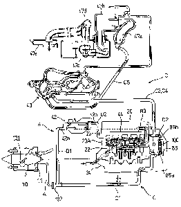
boat 1 is floated. Fig. 20 shows the circulation path of cooling water.
Cooling water is introduced via a cooling-water introduction hose A from a
cooling water inlet port 131 on the downstream positive-pressure side of the
impeller 11 of the jet propulsion pump 10. The cooling-water introduction hose
A is branched on the downstream side of a one-way valve 132 to a cooling water
hose B1 and to a cooling water hose Cl to form a first cooling water path B
and a
second cooling water path C.
The first cooling water path B is a path leading to the internal combustion
engine
main body 20A via the intercooler 42 and the exhaust manifold 44. The cooling
water hose B1 is connected to an inflow connecting pipe 42a on the left side
of the
intercooler 42, and a cooling water hose B2 that extends to the other side
from an
outflow connecting pipe 42b on the right side of the intercooler 42 is
connected to
WH-13148/cs
, , , ~..~..
I Y 111
CA 02586882 2007-05-01
-29-
an inflow joint member 44b attached to the rear portion of the water jacket of
the
exhaust manifold 44 (see Figs. 5, 6, 7).
As shown in Figs. 5 and 6, a cooling water hose B3 is connected to an outflow
joint member 44c attached to the upper portion of the exhaust manifold 44. A
cooling water hose B4 is connected to the cooling water hose B3 via a
branching
connecting pipe D. The cooling water hose B4 is connected to a lead-in joint
member 22a of the cylinder block 22.
The water jacket of the cylinder block 22 communicates with the water jacket
of
the cylinder head 23.
Accordingly, in the first cooling-water path B, the cooling water that has
passed
through the cooling water hose B1 flows into the intercooler 42 to cool the
intake
air, and then passes through the cooling water hose B2 and flows into the
water
jacket formed in the exhaust manifold 44 to cool the exhaust manifold 44. The
cooling water then passes through the cooling water hoses B3, B4 and flows
into
the water jacket of the cylinder block 22 of the internal combustion engine
20,
and circulates in the water jacket of the cylinder block 22 and the water
jacket of
the cylinder head 23 to cool the internal combustion engine main body 20A
before being discharged to the outside of the boat.
On the other hand, the second cooling-water path C is a path leading to the
exhaust pipe 47a via the oil cooler 100. The cooling water hose Cl is
connected to
an inflow connecting pipe 85a in a lower portion of the oil-cooler
accommodating
portion 85 in the oil cooler 100. A cooling water hose C2 extending from a
cooling-water outflow portion 85b in an upper portion of the oil-cooler
accommodating portion 85 is connected to a cooling water hose C3 via the
branching connecting pipe D. The cooling water hose C3 is connected to a
cooling water hose C4 via a connecting pipe 135 installed in an upper portion
of
the exhaust manifold 44. The cooling water hose C4 extends rearward along the
right-side surface of the cylinder head cover 26 to be connected to an inflow
connecting pipe 43a of the turbo-charger 43 (see Figs. 5, 6).
WH-13148/cs
4 . 4
CA 02586882 2007-05-01
-30-
As shown in Fig. 20, the cooling water that has flown into the turbo-charger
43
reaches the water jacket formed in the exhaust pipe 47a, and after the exhaust
pipe 47a, sequentially passes through the backflow prevention chamber 47b, the
water muffler 47c, and the piping 47d before reaching the water chamber 47e.
Accordingly, in the second cooling-water path C, the cooling water that has
passed through the cooling water hose Cl flows into the oil-cooler
accommodating portion 85 of the oil cooler 100 to cool lubricating oil, and
then
passes through the cooling water hoses C2, C3, C4 and flows into the water
jacket of the turbo-charger 43 to cool the turbo-charger 43. Thereafter, the
cooling water reaches the water jacket of the exhaust pipe 47a, takes in the
exhaust air while cooling the exhaust pipe 47a, and sequentially passes
through
the backflow prevention chamber 47b, the water muffler 47c, and the piping 47d
before reaching the water chamber 47e leading into the water to be discharged
into the water.
The branching connecting pipe D, which is commonly used for the first cooling-
water path B and the second cooling-water path C described above, also forms a
bypass passage communicating between the cooling water hose C2 located
downstream of the oil-cooler accommodating portion 85 of the oil cooler 100,
and
the cooling water hose B4 located upstream of the water jacket of the cylinder
block 22.
Accordingly, a part of the cooling water that has passed through the oil
cooler
100 is mixed, via the bypass flow passage of the branching connecting pipe D,
into the cooling water that has flown out from the water jacket of the exhaust
manifold 44, and flows into the water jacket of the cylinder block 22.
The cooling system of the internal combustion engine 20 according to this
embodiment is configured as described above.
When the cooling water introduced from the cooling water inlet port 131 of the
jet propulsion pump 10 is made to directly flow to the water jackets of the
cylinder block 22 and cylinder head 23 of the internal combustion engine 20,
WH-13148/cs
I 1
r 1 I 1N N.
CA 02586882 2007-05-01
-31-
supercooling may occur before the internal combustion engine 20 is warmed up,
resulting in so-called dilution whereby fuel passes through the gap between
the
piston and the cylinder and dissolves into lubricating oil to dilute the
lubricating
oil.
In view of this, in the cooling system according to this embodiment, in the
first
cooling-water path B mentioned above, the cooling water that has been raised
in
temperature through the exhaust manifold 44 that warms up quickly is made to
flow into the water jacket of the cylinder block 22 via the cooling water
hoses B3,
B4 to prevent supercooling of the intexnal combustion engine 20, thereby
alleviating dilution and suppressing oil degradation.
Once the internal combustion engine 20 has been warmed up, the temperature of
the cooling water that has passed through the exhaust manifold 44 is too high.
In
view of this, the cooling system according to this embodiment includes the
branching connecting pipe D that also serves as a bypass passage communicating
between the cooling water hose C2, which is located downstream of the oil-
cooler accommodating portion 85 in the second cooling water path C, and the
cooling water hose B4 in the first cooling water path B. A part of the cooling
water that has passed through the oil cooler 100 on the upstream side of the
turbo-charger 43 and whose temperature is not so high is made to pass through
the branching connecting pipe D to be mixed into the cooling water that has
passed through the exhaust manifold 44. The cooling water that is made to flow
into the water jacket of the cylinder block 22 is thus maintained at an
appropriate
temperature, thereby enabling efficient cooling of the internal combustion
engine
20.
A part of the cooling water that has passed through the oil cooler 100 is
diverted
into the bypass passage of the branching connecting pipe D, and all the
rerriainder of the cooling water flows through the second cooling water path C
as
it is into the water jacket of the turbo-charger 43 to cool the turbo-charger
43, and
then cools the exhaust pipe 47a and the like.
WH-13148/cs
4 1
CA 02586882 2007-05-01
-32-
Further, in the lubricating system mentioned above, when the temperature of
lubricating oil is equal to or higher than a predetermined temperature, the
oil
thermostat 105 opens the oil cooler 100 side to cool the lubricating oil, thus
promoting the cooling of the internal combustion engine 20.
On the other hand, when the temperature of lubricating oil is lower than the
predetermined temperature, the oil thermostat 105 opens the bypass oil passage
106 side so that the lubricating oil is bypassed without passing through the
oil
cooler 100. Accordingly, the lubricating oil is not cooled, thereby promoting
warm-up and preventing supercooling from occurring during cold running.
Although various preferred embodiments of the present invention have been
described herein in detail, it will be appreciated by those skilled in the
art, that
variations may be made thereto without departing from the spirit of the
invention or the scope of the appended claims.
WH-13148/cs