Note : Les descriptions sont présentées dans la langue officielle dans laquelle elles ont été soumises.
CA 02587977 2007-05-08
PIPE CONVEYOR
FIELD OF THE INVENTION
The application of this invention lies in many fields of conveying and
processing materials, it is generally applicable in any application that
requires
transport or conveying of material. One application is in the field of diamond
recovery by the process of diamond gravel sorting. The invention is favourably
applicable, for example, in loading ships, conveying material in factories and
industrial process plants. Apart from mineral beneficiation and industrial
conveying the invention can be applied in the food industry, as an example of
its versatility.
BACKGROUND
Conveyor belts that have the feed portion of the belt located inside a pipe
are
described in US patent 5,052,545, in the applicant's earlier South African
patent 2002/00644 and in US patents 5,735,386, 6,405,855, 6,422,381 and
6,675,958.
The applicant's patent 2002/00644 dealt primarily with diamond recovery
where the conveyor belt feed being located inside a pipe improved security by
enclosing the diamond-bearing gravel, with its return portion located below,
as
in the above cited US patents. The pipe has a hinge at an intermediate
position of its length, capable of hinging the pipe into a reduced length, for
transport to remote sites, with the belt still in the pipe. Idler rollers are
provided
at intervals to support the belt on its return stretch. The drive roller,
return idler
and idler roller supports are mounted on the pipe so that assembly of these
items on site and set up is not required, so that maintenance is simplified. A
key difficulty with this apparatus, however, is that a new belt cannot be
installed in the pipe except by threading it through the pipe and then on site
joining the ends to form a closed loop; a factory formed joint is not an
available option. From practical experience of working in conditions where the
material is damp or wet it adheres to the belt and causes spillage; this
requires the belt to be scraped clean and belt scrapers do not function well
1
CA 02587977 2007-05-08
with the type of belt joint that is possible on site, they become damaged or
ineffectual and/or damage the belt at the joint.
THE INVENTION
The present invention provides an improved conveying apparatus, the
apparatus including an endless conveyor belt with both its feed and return
portions enclosed in a pipe, with at one end a drive roller for driving the
belt
and at the other end an idler roller, with the feed portion above the return
portion and the feed portion cupped by the pipe.
An option that is possible is to provide the idler roller with a drive as
well.
The term "cupped" refers to the edges of the feed portion of the belt being
lifted up so that the belt assumes a trough shape, the better to hold the
material; the belt is cupped by the pipe as the belt is wider than the pipe in
the position where it is located above the return portion of the belt.
Preferably
the drive roller and the idler roller are located at elevated positions
selected so
that the feed portion of the belt at the top of the roller is located above
the
level of the diameter of the pipe. The elevated level is also selected so that
the roller is less exposed to foreign material at ground level and is more
accessible for adjustment, maintenance and replacement.
This arrangement allows a belt to be made up in the factory to a required
length, with a high quality vulcanised joint or splice and inserted into the
pipe,
likewise it can be removed for replacement by simply pulling the belt loop out
of the pipe. Spare factory-made belts may be kept on site to allow quick
replacement in the case of belt failure thus maintaining optimum production.
3t1
In accordance with a preferred embodiment of the invention the pipe is made
of a plastic material or other material of low coefficient of friction, the
pipe
supported by lying in a semi-pipe or trough of steel.
2
CA 02587977 2007-05-08
The semi-pipe of steel may be a hemi-pipe, that is a pipe slit along its
length
on its diameter, however, the pipe may be a semi-pipe slit along its length at
position resulting in less than the diameter or more than the diameter, the
latter case to embrace the plastic pipe more fully.
Preferably the plastic pipe is given a precise fit in the steel half-round
pipe or
hemi-pipe, this can be done by suitable selection of the outer diameter of the
plastic pipe and the inner diameter of the steel pipe. In accordance with a
preferred embodiment of the invention the close fit is provided by partially
splitting the half round steel pipe centrally along its length so that it can
be
bent to suit the diameter of the piastic pipe, held in this position by
clamping,
spot welded along the length of the partial split. The plastic pipe is then
removed and the split Is welded along its length to give a near perfect
plastic
pipe to steel pipe fit.
The plastic may be a poly vinyl chloride (PVC), polyethylene (PE) material or
a high density polyethylene (HDPE), just to name three possible materials,
any other plastic selected to optimise performance may be used.
Using plastic pipes instead of steel pipes, benefits from the low coefficient
of
friction, for example N= 0,4 rather than N= 1,4; the lower friction provides a
lower energy requirement which is important in remote sites and lower heat.
The plastic pipe also has a lower weight than a steel pipe, due to the lower
density of plastic than steel; this results in a weight saving of up to 40%.
The plastic pipe has the further advantage of being rust free which is
important at sea or coastal conditions while the half round steel pipe can
easily be galvanised or powder coated which is difficult in the case of a
complete pipe of any appreciable length. However, use in the sun shows that
unsupported plastic pipes sagged, leading to difficulties as the plastic pipe
had not enough rigidity to support itself over any appreciable length. It will
be
appreciated that the plastic pipe weight, the belt weight and the load weight
must all be supported.
3
CA 02587977 2007-05-08
In accordance with a preferred embodiment of the invention, the belt surface
is ground to an accurate thickness dimension in situ on the apparatus; this is
done by means of a grinding roller being mounted adjacent the driving roller
or
the idler roller, adjusted to a required position and rotated so as to grind
off
high spots of the belt as the belt is driven. Once the belt is accurate the
grinding roller may be removed. Even factory produced high quality beits have
increased thickness at the joint, this causes difficulty with belt scrapers,
grinding the belt in situ creates a highly accurate belt surface for scraping
and
trouble-free belt scraping becomes possible.
Preferably the apparatus has a belt scraper added to it. The grinding of the
belt may be adopted even for a belt that has been spliced in the field, if
necessary.
A right cylindrical (straight profile) of the drive roller is preferred with
two
peripheral flanges to prevent material spillage where the belt flattens out on
going over the pulley. The drive roller is the one which places the feed
portion
of the belt in tension in the pipe, the drive roller is preferably given a
rubberised surface to increase the grip between the belt and the pulley and
reduce or prevent slippage. The two peripheral flanges can be bolted each in
two halves onto the pulley.
Preferably two guide roll sets are provided at each of the two ends of the
pipe,
where the belt exits and enters the pipe, positioned so as to guide the edges
of the belt so that they do not abrade the ends of the pipe. The roll sets are
mounted on the pipe ends with axes of rotation upright (that is, at ninety
degrees to the axes of rotation of the drive and idler rollers, which are
horizontal). Each roll set comprises two rolls that are positioned to roll
against
the edges of the feed and return portions of the belt.
The drive and idler rollers are adjusted in the known way by shifting the left
and right plummer blocks or other bearing mountings longitudinally for correct
tracking of the belt on the rollers. The two flanges, together with the guide
roll
4
CA 02587977 2007-05-08
sets and the pipe itself help to retain the belt in a central position which
once
set up needs very little or no further adjustment.
The two split flanges of steel or any suitable plastic material are bolted to
the
sides of the drive pulley so as to prevent spillage of conveyed material as
the
belt assumes a horizontal flat form as it exits from the pipe from a half
round
form that it has inside the pipe.
The driving roller and/or the idler roller can be made with a convex profile
or
camber to ensure self-centring of the tracking of the belt on the roller. The
drive roller may be given a rubberized surface and a larger diameter (which
increases contact area) to provide better transfer of the drive force from the
roller to the belt and less slip for a given belt tension.
Thus the present invention provides a procedure for effective belt scraping on
any conveyor belt of first grinding the belt to an accurate thickness over it
full
length by applying a roller grinder to the belt at a drive roller or idler
roller,
adjusted to grind a consistent thickness while driving the belt, then applying
a
belt scraper to the belt.
The belt scraper may be of less complex type than is often required, because
of the enhancement of the belt by the process described, of grinding the belt
to an accurate thickness in situ, The belt may be of the type having multiple
contiguous scraping elements, each spring loaded and adjustable.
?5
With both the feed and return portions of the belt being located inside the
pipe
transport and handling is less likely to cause damage, the belt can be pulled
out of the pipe beforehand.
In accordance with a preferred embodiment of the invention there is provided
a dolly consisting of a frame and road wheels (or cross-country wheels) with
clamps for clamping to one or more pipes of the apparatus according to the
invention, together with a tow hitch also adapted for connexion to the pipes,
5
CA 02587977 2007-05-08
for towing them behind a tow vehicle. This makes the overland transport
highly practical and economic in suitable circumstances.
Particularly long pipes can be manufactured so that they can be reduced in
length for transport, e.g. by folding as described in the applicant's patent
referred to above or by being split by disconnecting a joint intermediate of
the
operational length of the pipe; e.g. a bolted flanged joint. This allows a
reduction of the pipe length to one suitable for more convenient and cost
effective transport, while at the same time allowing quick set up of the plant
at
a site, for use. The quick set up is enabled because when the pipe is hinged
out to its full operative length, the belt is already in the pipe and on the
idlers,
drive and return idler. So the usually demanding task of aligning the drive
roller and return idler and other idlers is obviated. The pipe confers
security
against theft from the material being conveyed.
Preferably the drive is bolted to the pipe in a way that allows its removal,
so
that if required it can be removed, e.g. for transport, should his make
handling
and loading easier.
Preferably similarly, the return idler is bolted to the pipe in a way that
allows its
removal.
A feeder trough can be added to the plant, adapted for conveying (e.g.
diamondiferous gravel) to the feed end of the conveyor, i.e. at the return
idler
end.
A delivery chute can be provided as well, and other components as may be
required or desired for various applications.
THE DRAWINGS
The invention will be more fully described by way of example, with reference
to the accompanying drawings, in which :-
6
CA 02587977 2007-05-08
Figure 1 is a photograph of the delivery end of a conveying apparatus,
Figure 2 is a photograph of the in-feed end of the conveying apparatus,
Figure 3 is a photograph of the in-feed end of the conveying apparatus with a
belt grinder mounted,
Figure 4 is a photograph end-on of the in-feed end of a conveying apparatus
with a belt grinder mounted,
Figure 5 is a photograph of the delivery end of a conveying apparatus,
showing the belt scraper,
Figure 6 is an end view of the scraper, partially sectioned,
Figure 7 is a side sectional view of the scraper,
Figure 8 is an enlarged view of a part of the scraper,
Figures 9 and 10 are an elevation and plan view respectively of a means of
transport of the apparatus,
Figure 11 is a perspective view of a partial length of the conveying
apparatus,
Figure 12 is a side view of the conveying apparatus,
Figure 13 is a side view if a conveyor according to the invention with
provision
for drying,
Figure 14 is a cross sectional view of the feed bin and pipe conveyor shown in
figure 13,
7
CA 02587977 2007-05-08
THE PREFERRED EMBODIMENTS
The improved conveying apparatus for a plant for recovery of diamond, other
precious and semi-precious stones and minerals, has an endless conveyor
with both its feed and return portions enclosed in a pipe. Figure 1 shows at
one end 1 a drive roller 2 for driving the belt 3 and figure 4 shows at the
other
end 5 an idler roller 6, with the feed portion 7 of the belt above the return
portion 8 and the feed portion cupped by the pipe 9. Figures 1 and 4 show the
edges 10 of the delivery and feed portions of the belt respectively being
lifted
up so that the belt assumes a trough shape, i.e. cupped; the belt is cupped by
the pipe all along the length of the pipe. The drive roller and the idler
roller are
located at elevated positions by being mounted on top of the beams 11 and
12 respectively; the feed portion of the belt at the top 13 of the idler
roller is
located above the level 14 of the diameter of the pipe. It is found that
surprisingly the drag on the belt is negligible, for example a mere 4 amps
drain on a 1,2 Kw. Varying lengths can be used, e.g. from 6 m to 12 m long,
according to application.
Figure 4 shows how the belt surface is ground to an accurate thickness
dimension in situ on the apparatus; a grinding roller 4 is mounted adjacent
the
idler roller, which is adjusted to a required position by screw adjustments 15
and 16 and rotated by the motor 17 in the opposite direction to the rotation
of
the idler roller, so as to grind off high spots of the belt as the belt is
driven.
Once the belt is accurate the grinding roller is removed.
The driving roller is made with a convex profile or camber as is seen in the
views if figures 5 and 6, to ensure self-centering of the tracking of the belt
on
the roller, after the idler roller has been set up orthogonal to the belt
direction.
The drive roller is driven by a chain 18 from a motor 19, running on sprockets
20 and 21. The motor and driving roller are mounted on the pipe by means of
transverse cradles extending between the two beams 11 and secured by
straps or hoop clamps 22, with a pedestal 23 for the motor, incorporating a
chain tensioning platform 24 . Beams 12 are mounted in similar way with
8
CA 02587977 2007-05-08
cradles and straps 25 to the other end of the pipe and carry the idler roller
in
plummer blocks 26 with screw adjustment 17; the grinding roller is also
mounted on the beams, on plummer blocks 27.
The views of figures 5 to 8 show that the apparatus has a belt scraper 28
added to it. The belt scraper has multiple contiguous scraping elements 29,
each spring loaded by a spring 30 and adjustable by screw 31 and lock nut
32. Each scraper element is made of "Vesconite" (trade mark) which wears
well to the shape of the belt, each being initially adjusted to the convex
shape
of the rubberised driving roller. The scraper elements are held between the
plates 33 and 34, which are bolted to the beams.
Figures 9 and 10 show a dolly 35 consisting of a frame 36 and road wheels 37
with clamps 38 for clamping to one or more pipes of the apparatus, together
with a tow hitch 39 also clamped to the pipes, for towing them behind a tow
vehicle 40. For example, apparatus comprising pipes up to 9 or 12 metres can
be transported in this way, in suitable circumstances.
A feeder trough can be added to the plant, adapted for conveying (e.g.
diamondiferous gravel) to the feed end of the conveyor, i.e. at the return
idler
end.
A delivery chute can be provided as well, and other components as may be
required or desired for various applications.
Figures 1 to 10 show use of an electric motor 19 with a chain drive to the
driven pulley, but an improved drive has been sourced in the form of a
motorized roller, that is the drive roller has an electric motor inside it. In
addition an electronic controller has been added, which provides control from
a computer screen of speed, provides a soft start and allows monitoring
current drawn etc.
Referring to figures 11 and 12 of the drawings, the improved conveying
apparatus 41 for a plant for recovery of diamond, other precious and semi-
9
CA 02587977 2007-05-08
precious stones and minerals, or transport of any material, like loading
sawdust onto a ship, for example, has an endless conveyor with both its feed
portion 42 and return portion 43 enclosed in a plastic pipe 44. The plastic
pipe
is supported by a steel hemi-pipe 45 which cradles the plastic pipe. Figure 12
shows at one end 46 a drive roller 47 for driving the belt 42-43 and at the
other end 48 an idler roller 49, with the feed portion 42 of the belt above
the
return portion 43 and the feed portion cupped by the pipe 44. The drive roller
is a motorised roller with an electric drive motor located inside the roller.
The
drive roller and the idler roller are mounted on top of the beams 50 and 51
respectively. Feed of material is provided by the funnel 52.
The beams 50 and 51 are mounted on the pipe by means of transverse
cradles 53, 54, 55 and 56 extending between the beams and secured by
straps or hoop clamps 57, 58, 59 and 60.
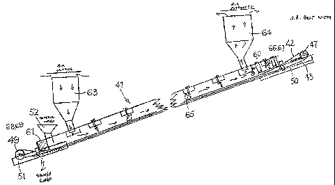
Referring to figure 13, there is shown a conveyor according to the invention
which is adapted for drying of the material being conveyed. The conveyor pipe
60 described with reference to figures 11 and 12, being a plastic pipe
supported by a half-round steel pipe, with drive and idler rollers and feeder
bin, the same reference numerals are used to indicate these parts and the
description above of them is referred to; the feed portion of the conveyor is
shown at 42 and the return portion at 43. In this example a sponge rubber
cushion 61 is inserted in the pipe to stop material rolling back. Figure 14
shows the part of the feeder bin that extends into the pipe, this has an
inverted U-shaped opening 62 at the lower end facing along the length of the
pipe. The effect of this is that if the belt stops the feed simply backs up
the bin
and stops also, once the belt moves the feed resumes and the rate of the feed
is determined by selection of the size of the opening 62.
The pipe has an air intake at 63, driven by a fan (not shown) in the intake,
which is directed into the pipe; the air may be heated by heating means if
desired or required; however, in hot sunny conditions if the plastic pipe is
black, solar heat is sufficient in many cases to dry the material to the
required
moisture content, for example less than 4%. An air extractor 64 also driven by
CA 02587977 2007-05-08
a fan is located near the other end of the pipe conveyor. The pipe has a
number of deflectors 65 mounted inside the pipe, turned this way and that so
as to turn over the material on the belt as it passes u the pipe towards the
delivery end at the drive roller 47.
REFERENCE NUMERALS
1 DRIVE END OF CONVEYOR
2 DRIVE ROLLER
3 CONVEYOR BELT
4 GRINDING ROLLER
5 IDLER END OF CONVEYOR
6 IDLER ROLLER
7 FEED PORTION OF BELT
8 RETURN PORTION OF BELT
9 PIPE
10 EDGES
11 BEAM
12 BEAM
13 TOP OF IDLER ROLLER
14 LEVEL OF PIPE DIAMETER
15 SCREW ADJUSTMENT
16 SCREW ADJUSTMENT
17 MOTOR
18 CHAIN
19 MOTOR
20 SPROCKET
21 SPROCKET
22 HOOP CLAMP
23 PEDESTAL
24 CHAIN TENSIONING PLATFORM
25 HOOP CLAMP
26 PLUMMER BLOCKS
11
CA 02587977 2007-05-08
27 PLUMMER BLOCKS
28 BELT SCRAPER
29 SCRAPING ELEMENT
30 SPRING
31 ADJUSTABLE SCREW
32 LOCK NUT
33 PLATE
34 PLATE
35 DOLLY
36 FRAME
37 ROAD WHEEL
38 CLAMP
39 TOW HITCH
40 TOW VEHICLE
41 CONVEYOR
42 FEED PORTION OF BELT
43 RETURN PORTION OF BELT
44 PLASTIC PIPE
45 STEEL HALF PIPE
46 DRIVE END OF CONVEYOR
47 MOTORISED DRIVE PULLEY
48 IDLER END OF CONVEYOR
49 IDLER PULLEY
50 BEAM
51 BEAM
52 FEED CHUTE
53 CRADLE
54 CRADLE
55 CRADLE
56 CRADLE
57 STRAP
58 STRAP
59 STRAP
60 STRAP
12
CA 02587977 2007-05-08
61 sponge rubber pad
62 inverted U-shaped opening
63 drying air intake
64 drying air exit
13